Design of a 30 inch [0.76m] binoscope by Mel Bartels
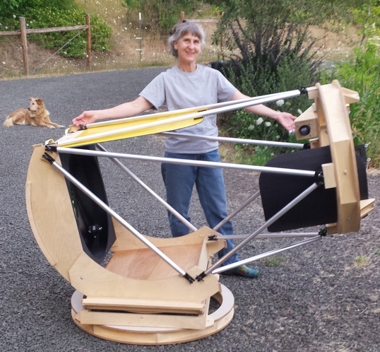
My 25 inch [0.64m] FR2.6 is a bigger success than I dared hope.
I want that wonderful large aperture super wide angle light going into both of my eyes. So I set my sights on a 30 inch binoscope with sub F3 focal ratio
I've long dreamed of building a binoscope after viewing through a number of wonderful binoscopes at the Oregon Star Party.
Memorable was an all night 'shootout' pitting Bruce Sayre's 22 inch binoculars against Dan Gray's 28 inch.
I've shied away from binoscopes: they are very challenging to build and operate and I've not seen a fast binoscope built to use 2 inch diameter coma correctors.
Seeing Robert Asumundi's 3D printed 8 inch binoscope though gives me hope that 3D printing can be used to build the complex IPD and focusing components.
At best I'll build a giant super fast binoscope, at worst I'll have a couple of 30 inch FR2.7 mirrors that I'll turn into standard telescopes.
There are considerable advantages to binoscopes:
- I see dimmer stars. The difference is clear: go outside on a dark night and compare one eye to both eyes. Can the difference be quantified? The surface area of a binoscope's two mirrors equals a single mirror 41% larger. With binoscopes I see a magnitude gain of about 20% for stars, more than a single scope but less than naively combining the apertures. In other words, based on my observing experiences with binoscopes, I anticipate that a 30 inch binoscope will have the magnitude grasp of a 36 inch telescope.
- Looking at nebula I see a major increase in contrast, nearing 80%. Here's where a binoscope really shines. The combination of two scopes exceeds that of the single mirror equivalent. Baed on my observing experience, I anticipate that a 30 inch binoscope will have the contrast of a 54 inch telescope.
- Another way to look at binoscopes is their equivalent focal ratio. In this case, each mirror is FR2.7, and the combined FR is 1.9.
- A milky smoothness when looking through a binoscope. Returning to a monoscope, the deep sky view scintillates with ugly mottling and artifacts. It takes a hour or more for these effects to subside. I consider this the greatest 'wow' factor of a binoscope.
- A wider angle, greater etendue view. At 6mm pupil, the lowest power a 12 inch monoscope can provide is 50x with a 2 degree field and etendue of 2200 cm^2deg^2, while an 8 inch binoscope can go down to 33x with a 3 degree field (a doubling of area) and etendue of 4400cm^2deg^2.
Serous binoscope drawbacks:
- They need two of everything.
- They are extremely difficult to build and operate in that both telescopes must point at exactly the same spot in the sky yet always maintain optical alignment, allow for IPD (InterPupillary Distance) adjustment from 55mm to 70mm, along with independent focusing.
- Secondaries are quite large.
- The observer can end up in ergonomically difficult positions.
- Fast binoscopes require two coma correctors which creates a major design headache.
- They have a large footprint, making transport challenging. For the proposed 30 inch binoscope, the footprint is 4'x'6 x 4' tall, calling for a separate trailer to haul the binoscope as it will have trouble fitting into the bed with canopy of a pickup.
Research what others are doing
Here are my inspirations and references:
Binocular history:
Design considerations
This project is all about building the best possible large fast binoscope, accepting the compromises, in order to see what high etendue light going into each eye will reveal.
Coma corrector considerations
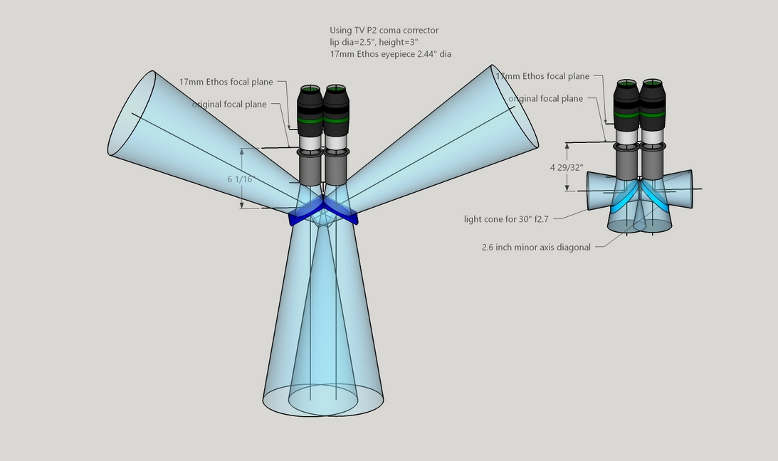
The P2 coma correctors present some design challenges. The tunable top will have to be removed and the threaded base machined back on a side. I looked at inserting the tertiary between the P2's upper and lower lens assemblies, but it is a tight fit and it means remounting the P2 lens sets. The alternative is to keep the P2 intact, adding 3 inches to the secondary to focal plane distance and an inch to the secondary size.
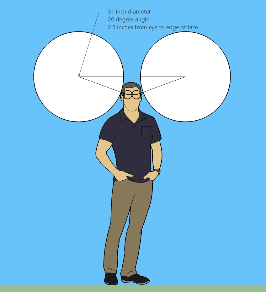
Head placement and secondary size
Here's my study of head placement with respect to the 30 inch mirrors and the resulting eye to secondary distances. Looks like I will need 18 inches from the secondary to the focal plane to avoid heads blocking the edges of the mirrors. One optimization I am considering is to trade some head blockage for a smaller diagonal size, for example, moving the head an inch into the mirror's light path blocks maybe 10 square inches but reduces the secondary size by an inch which is worth 30 square inches. The head's intrusion results in each eye seeing the obstruction on opposite sides of the field of view, so it is possible that the brain's conscious computation of the image will compensate somewhat.
Naively if a traditional reflector then the secondary size need only be 6.5 inches m.a. (using a short L of 17 inches and FR of 2.73). For a sub-F3 binoscope, we need five inches for the light path bending due to the P2 coma corrector, 2.5 inches for the eye to the side of the head distance and a minimum of 0.5 inches for the tube. That gives an additional distance beyond the mirror's edge of 5+2.5+0.5=8 inches. Adding this 8 inches to the mirror's radius gives an L of 23 inches (8+15). The minimum sized secondary then is 8.5 inches m.a. x 12.0 inches major axis with an obstruction of 8%. Rather sobering in size and weight though the primary mirror to focal plane distance is only 82-23+5=64 inches, making for a relatively short tube.
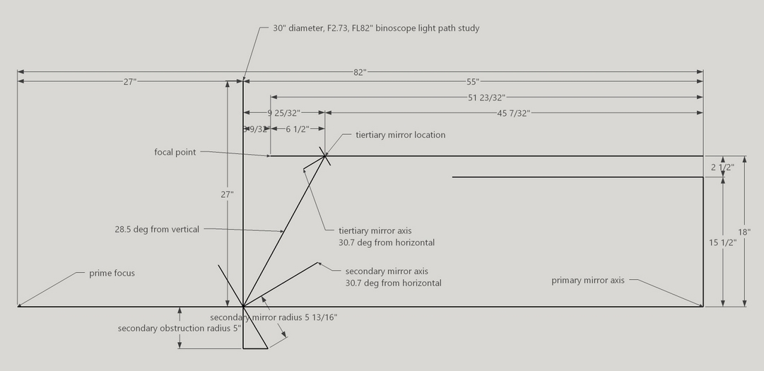
If we increase size to the maximum I am willing to consider, a 1:3 ratio with the primary, in this case a 10 inch secondary, then we have a maximum L of 27.3 inches (10*FR of 2.73=27.3). Let's make it 27 inches even. The P2 coma corrector needs to be 18 inches from the primary mirror's center. This means that we can bend back the light angle to shorten the tube further. How much? From my secondary light bending angle study, the light can be bent back at a 28.5 degree angle resulting in the focal point being 51.7 inches from the primary mirror's center, about the eyepiece height as my 25 inch FR2.6 of 48.5 inches. However, when the telescope is pointed vertically, the eyepiece height plus the eye relief will need to be added to get the eye's height from the primary mirror's center. That's about 6 additional inches for the Ethos 17mm eyepiece for a total height of ~58 inches. The secondary needs to be 10 inches minor axis by 11.6 inches major axis for an obstruction of 10%, just 2% more than the right angle diagonals analyzed in the previous paragraph.
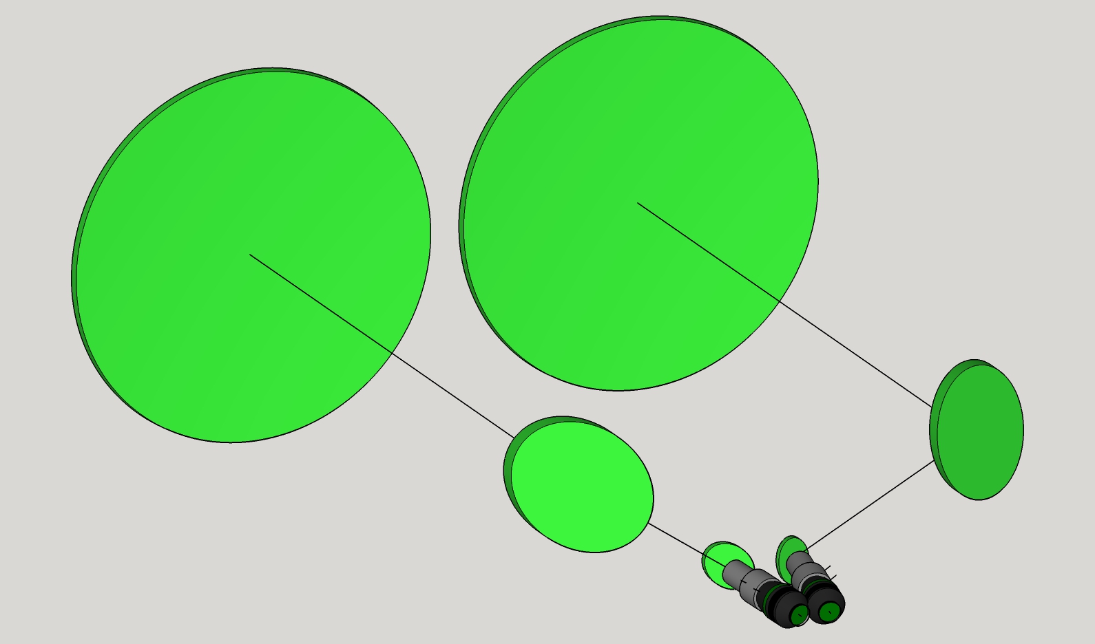
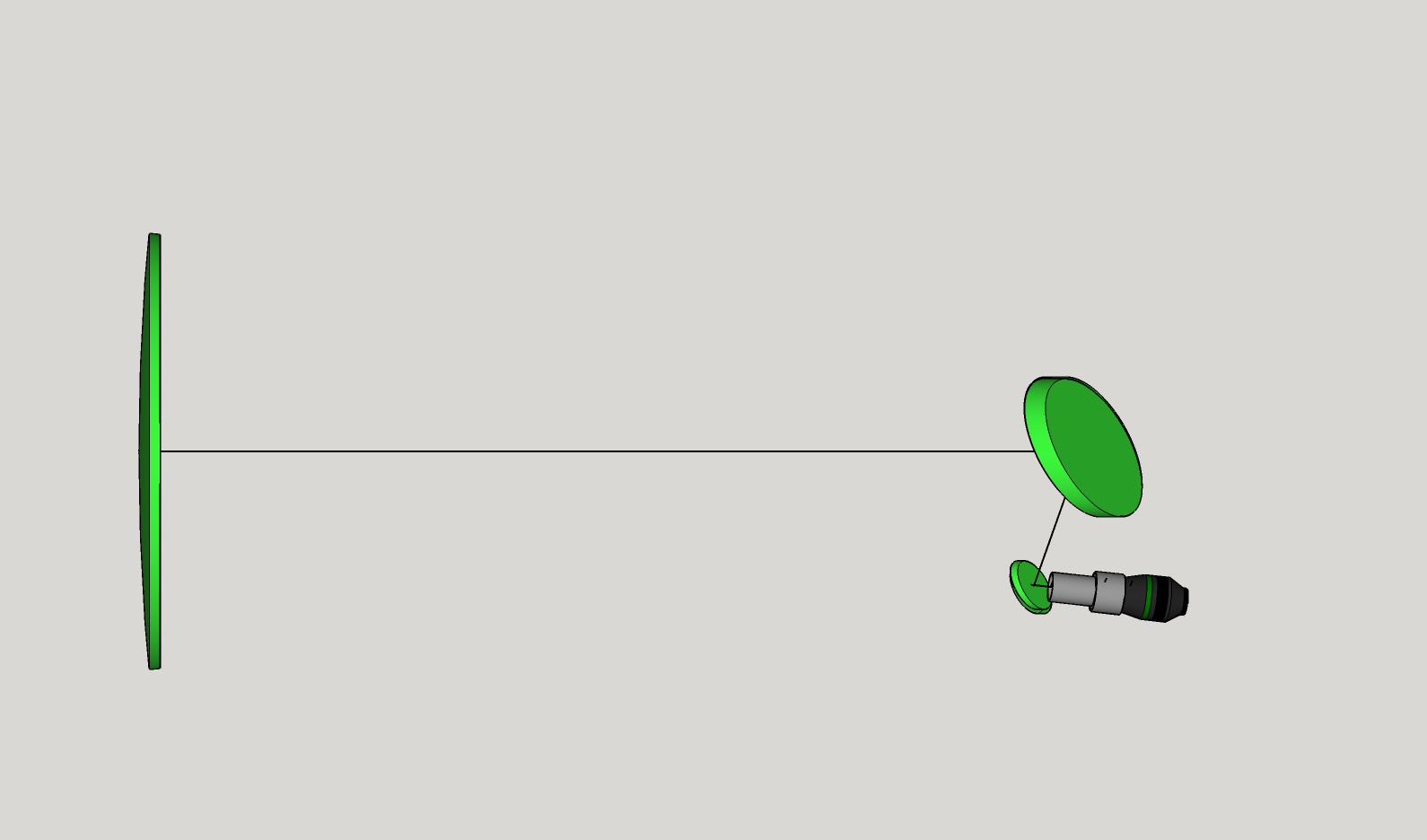
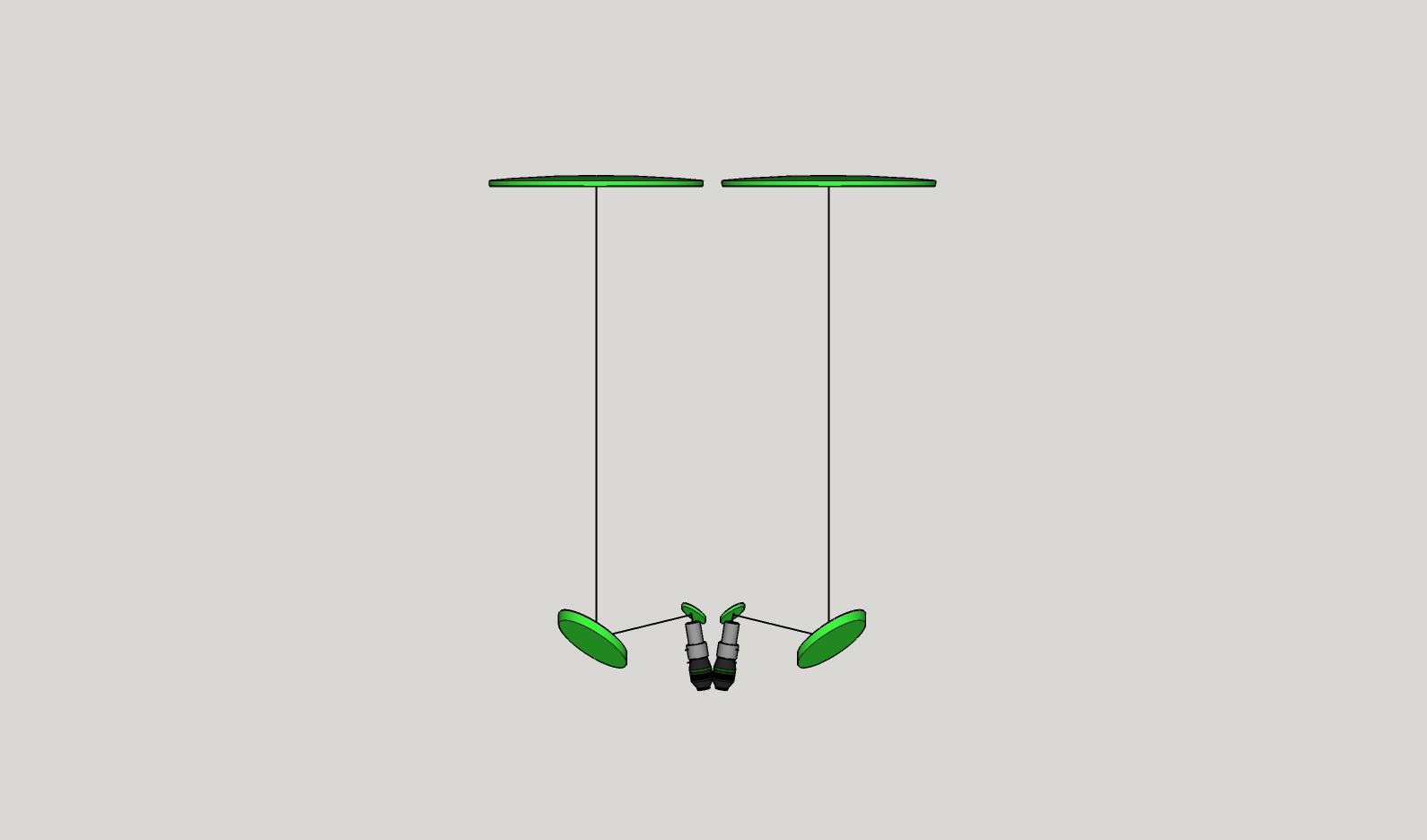
Optical path orientations
Here's my worksheet (Sketchup graphic) of my study of orientations. It was a worthwhile and interesting exercise though time consuming too.
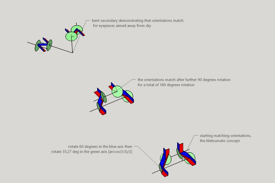
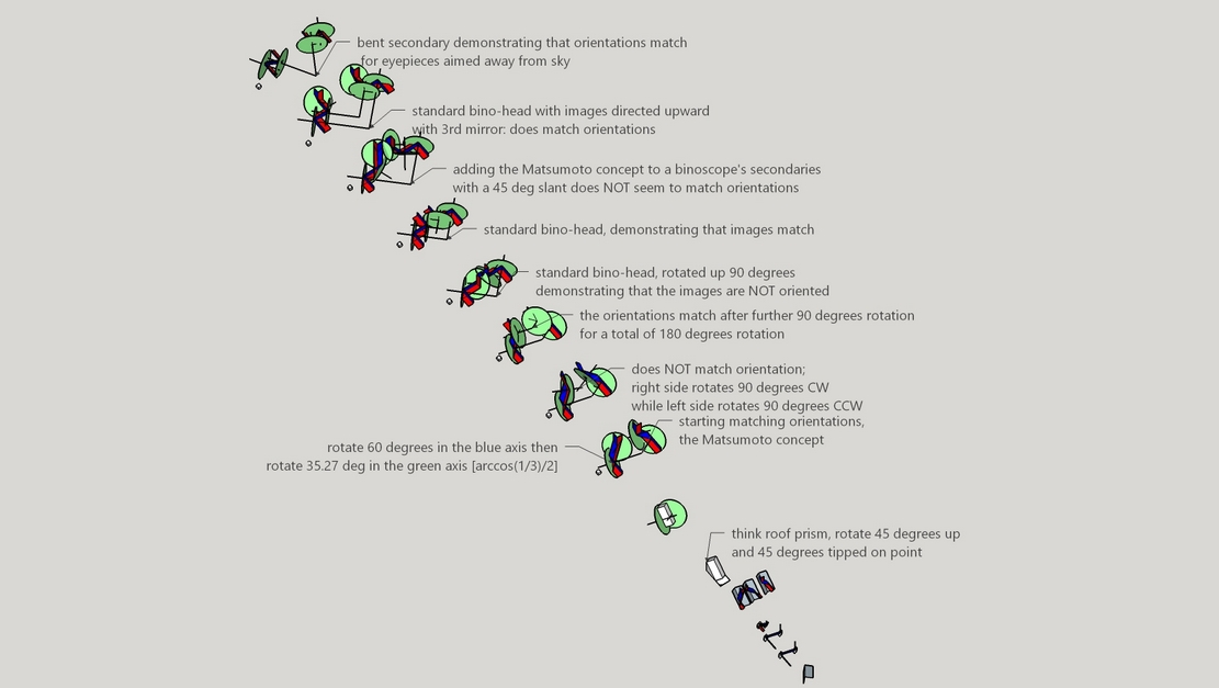
Image merging
Imaging merging is done in two ways:
- Two separate tube assemblies aligned at the tube level
- Sliding primaries where one primary moves vertically and the other moves horizontally
According to Arie Otto, the steps to merge the image by moving the primary mirrors are:
- Separately collimate each telescope without the tertiairy mirrors in place: first the secondary mirrors, then the primary mirrors
- Insert the diagonals with tertiary mirrors and collimate the tertiairy mirrors
- Merge star images by de-collimating the primary mirrors
- Re-collimate the primary mirrors by adjusting the screws on the secondary mirror holders
- Repeat steps 3 and 4 if necessary
Here, image merging uses the collimation screws; consequently collimation needs to be touched up after image merging. This concerns me because the optical alignment must be perfect at FR 2.7. I suppose the impact of this depends on the frequency that the images must be re-merged. Safest choice is imaging merging by aligning two separate tube assemblies, where each tube assembly is collimated ahead of time and stays collimated throughout the observing run.
Conclusion
Here's my design (note the stretched altitude axis rims to bring up the eyepiece height when pointed near the horizon):
(You now have to sign into Sketchup to see it)
While the height is amazingly short, the footprint is dauntingly large and very large secondaries a project in themselves.
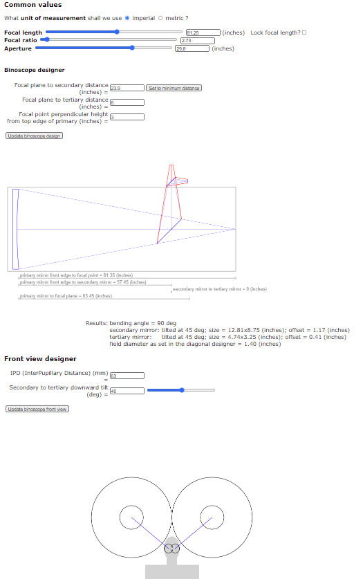
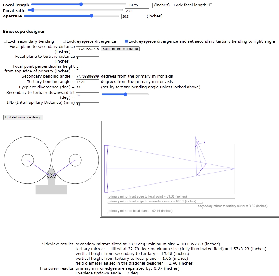
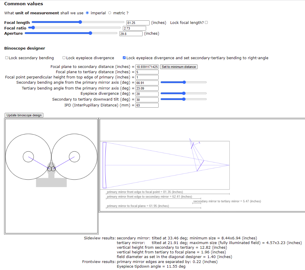
Here is my design thinking using my NewtDesigner tool.
An interesting idea by Clive Milne is to diverge the eyepieces, then either laterally offset them to re-center the fields or mis-align the optical tube assemblies to compensate. This leads to a more compact 3D design with smaller secondaries.
Here are some images and discussions.
See the Cloudy Nights discussion
along with this diagram showing how to offset the eyepieces
and this post showing which rotations are allowed.
Making the matching mirrors
Go here to view my mirror making log
end