Copyright Guy F. Brandenburg
Reformatted by Mel Bartels from Bob May's page at http://bobmay.astronomy.net/foucault/leontop.htm for readability.
The differences between reflecting telescopes and achromatic refractors have long been the subject of discussion. In fact, both these instruments have rendered astonishing services to astronomy and science has adopted both of them. With reflecting telescopes of large dimensions, such as William Herschel has constructed by his own hand, one seeks a distinct and detailed perception of celestial objects. As for achromatic objectives, which can never become as large, the degree of stability which they have proven themselves capable of has made them especially good for precise observations, such as determining positions of stars and other objects. The roles thus having thus been divided, the reflecting telescope keeps its importance only if it greatly preserves its superiority with respect to its optical properties.
In England, where the struggle has been vigorously sustained in favor of reflective instruments, large metallic mirrors remain in small numbers and the expense which they have required have not been such as to encourage numerous other experiments of the same type. Let us also add that these mirrors are so heavy that people have been reluctant to transport them up to the summits of mountains, the only points on the globe from which one has the opportunity to use the full power of such instruments. Due to this state of things it seemed to us that it would be better to substitute glass for metal in the construction of the mirror, as long as one could coat the surface with metal after having polished it. Concerning this, the wet-process silver plating via the Drayton method leaves nothing to be desired. The cold solution, upon contact with the glass, deposits on the surface of the glass a thin layer of silver metal which, once dried, assumes a very beautiful polish when rubbed with a piece of silk impregnated with iron oxide [i.e., rouge - tr.].
On February 16,1857 the Academy of Sciences examined a 10cm [note: is this radius or diameter? Not clear - tr.] mirror obtained as described above which, when mounted in a Newtonian telescope, produced good images and allowed a magnification of about 150 to 200 times. The mirror still has its original silver plating. It has been preserved as the first specimen to be presented to a learned society.
[Note by Foucault in the original text: During its session of December 7, 1857, the French Academy of Sciences received a notice based on an article in the Augsbourg Gazette, concerning the opening of his workshops in Munich.) Here below we reproduce the passage in which the first attempts of M. Steinheil:
["Another interesting novelty for astronomers is the new telescope mirrors made of glass. By using Liebig's method for silvering mirror glass, metal layers can be deposited which are so good that even the rear of the silver forms a perfect mirror (or can easily be made to do so with suitable polishing agents). As a result, if normal glass is ground on only side to an exact spherical concavity, it can be silvered to give a telescope mirror which, even if it tarnishes over time, can be restored with only a little effort, as the exact shape is preserved by the glass. We have looked through a telescope of this kind with a 4" aperture which shows a marvelously clear, bright image at 100x. It is obvious that powerful telescopes can be very easily and cheaply made in this way." [(Allgemeine Zeitung, No. 84, Monday, March 24, 1856.)]
After the presentation of the first 20 cm [this may be a typographical error; may have intended 10 cm. - tr.] diameter telescope with a 50cm focal length (interestingly a F5 mirror if the diameter was supposed to be 10cm and a F2.5 - a very short focal length - if the dimension really was 20cm - Bob), we have obtained without difficulty a second which is 22cm in diameter with a focal length of 1.5 meters (about F6.8 which is a more reasonable focal length for a telescope of that era for a fast instrument - Bob). Then, in trying to make one with a diameter of 42 cm, the workman in charge of figuring the mirror was unsuccessful at doing so, even though he tried five different times. This has forced us to recognize the limitations of the procedures ordinarily employed to produce smaller surfaces.
Faced with the failures which threatened the hopes we had placed on this new type of mirror, we felt compelled to study the figure of the surfaces which, although worked with the greatest care, still would not produce the desired optical effect. From these studies three examining procedures have emerged which are directly applicable to concave reflecting surfaces and with the help of which one can recognize, with the required degree of precision, whether these surfaces are more or less correctly spherical. We have thus verified that opticians rarely construct surfaces which belong to the family of spheres, and that these surfaces depart all the more from spheres as they become larger. We have thus, so to speak, put our finger on an essential point which constantly recurred in the work on the 42 cm mirror, and this verification was so clear and so manifest that it suggested the idea of locally retouching the surface without altering the finish of it. This attempt, which was not at all encouraged by the expert workmen involved, nevertheless succeeded perfectly. From that moment on, our endeavors were freed from all obstacles and took on a new impetus.
In effect, as soon as we had acquired the proof that the working of a good surface did not necessarily depend on getting everything correct at once, as soon as it was demonstrated that one could return to the job indefinitely, the development was no longer directed at arriving precisely at a sphere. Instead, we wanted to modify, by degrees, the optical surface in order to approach the parabolic curve which alone is capable of bringing all the rays from a parallel bundle to a common focus.
The optical examination procedure which at first served to recognize the sphericity of the surfaces, modified in light of the theory of conjugate foci of an ellipse, and combined with the method of local retouching soon permitted to modify any surface of revolution furnished by the artisans from a sphere into a paraboloid, while passing through all by the intermediate ellipsoids. In this way these instruments, freed from the aberrations which compromised the clarity of their images, could be reduced to shorter focal lengths and enlarged proportionately in their three dimensions.
We limited ourselves to telescopes with a length not more than six times the diameter of the mirror. We adopted this constant ratio between the diameter and the focal distance only after having assured ourselves that the exact convergence of the ray bundle is the only condition that must be filled in order for an instrument to give its full effect. The parabolic surface expressly fills this condition; this is why it conveys to the telescope a resolution or, as they say, an "optical power" which, if measured with care, shows itself to be independent of the focal length and to be proportional to the diameter of the mirror. In deriving precise rules for measuring these optical powers whose appreciation is somewhat arbitrary, we wanted to furnish to those who use telescopes a way of calculating directly the value optical power. Moreover, we have discovered that for any telescope of a given diameter there exists an absolute power limit. This limit depends on the physical properties of light and puts a boundary on how much magnification can be obtained.
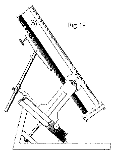
Freed from the enormous weight of metallic mirrors and from the excessive length imposed by the use of spherical surfaces, the telescope becomes much easier to handle. We therefore added an extra benefit by placing it on a light-weight equatorial mount made of wood.
In publishing this article, we propose not only to share the results which we have acquired, but we also want also to making known the practical procedures which have helped to obtain them. Without wishing to go into too much detail, we will put ourselves in the place of those who would like to take advantage of these same procedures and we will explain what steps to take to attain the same degree of success.
Firstly, we will describe the various geometric optical procedures by which one explores concave spherical surfaces. Next, we will extend the general application of the same procedures to the study of surfaces having conical sections, and we will show that these examination procedures, which are called upon to keep check upon one another are more than sufficient to direct the manual work with which one intends to produce the desired surface.
Passing thus from the application to the procedures we will borrow from the arts the means of preparing mirrors and of dealing with the surface of the glass together and of producing by local retouching a correct surface. We will discuss in detail the characteristics of a perfect surface, and we will define what we mean by optical power.
Then we will give practical details for silvering glass surfaces, no matter how large they may be, by the Drayton procedure. We will indicate the precautions to take in order to prevent the deformation of mirrors and to adapt them to telescope tubes. We will discuss the composition of eyepieces, and we will finish with a description of a practical wooden mount particularly applicable to short focus telescopes.
When a mirror does not produce good images, normally one simply rejects the surface without seeking to find out exactly where its faults lie. The surface is worked over again, and the work is repeated to the point where the mirror is deemed good enough. But on this point -i.e., what is success -opinions quite often differ. However, there are ways to tell if a surface has in fact reached a figure which is suited to the requirements for it to function.
Let us suppose that we need to verify a concave, spherical mirror. This sort of mirror has the property of returning, without distortion, all rays of light that originate from the center of curvature, back to that same point. Distributed in space around that center, and at a very small distance from it, is an infinite number of pairs of conjugate foci, which enjoy - as far as can be detected - the same property. Now imagine a point of light located right next to the center of curvature. On the exact other side of that center, an image of that point of light will be formed, which we can observe with a low-power microscope. If the surface is perfect, then the point is well-defend, the image is clear, and is surrounded by diffraction rings. Also, the changes which it undergoes on one side and the other of the focal point, when one moves the microscope in and out of focus, are symmetrical [i.e. identical]. Such are the characteristics of a perfect focus formed by a cone of rays which all cross at the same point in space.
If the image is not perfect, then when one attempts to bring the light to a focus, one cannot produce as clear an image. However, at some point the light concentrates to a maximum, and we can consider that to be the true focal point. If the image at that point is round, then we can conclude that the surface of the mirror, while not being exactly spherical, is at least a surface of revolution around a center. We can then be certain that when one moves to one side or the other of the point of best focus, we will observe different and complementary patterns: light and dark concentric rings [lit. condensations and rarefactions of light] will appear in a complementary manner on either side of the focal point. These changes indicate variations in the radius of curvature in the corresponding zones of the reflecting surface.
A bit of thought will easily show in which directions those changes occur. When we move the eyepiece forward, and pass in front of the focal point, we observe the status of the bundle of rays ahead of its point of convergence. If this point is not the same for all the various concentric zones on the mirror surface, then those zones which have the shortest focal length will produce, on the observing plane, a premature intensification of light, indicating a too-short focal length. The exact opposite occurs for zones where the focal length is too long. If we now draw the microscope backwards in such a way as to observe the status of the bundle of rays after they cross each other, we should observe the exact opposite phenomena, and these should bring us to the same conclusions.
Generally, with well-made surfaces, the deformations in shape take the form of gradual changes in the radius of curvature, which varies slowly and in small amounts and in a uniform direction from the center to the circumference of the mirror. Also, the two symmetric images observed to one side and the other of focus normally appear as circles, one with the brighter part towards the center and the other one towards the periphery.
When the surface being examined is not one of revolution, one is warned of that fact by the deformation of the images, which are not round, but divide themselves into unequal subdivisions.
This method of examining concave surfaces is sufficiently rigorous to find the smallest imperfections. But it works best of all when it is necessary to decide whether the mirror surface is one of revolution [i.e., is not astigmatic - trans.]. However, when one wants to perform local refiguring of the mirror, it is useful to find more precise information on the variations in the radius of curvature. In such a case, it is time to use a second method, based on an entirely different principle.
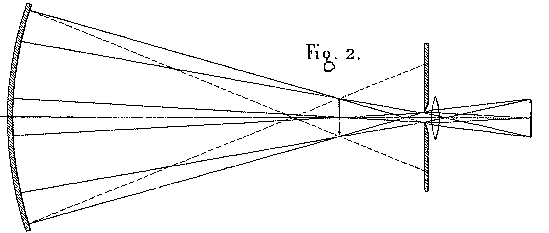
In the region around the center of curvature, we set up two straight lines, very close to each other, such as the two edges of a metal wire one millimeter in diameter. This object is illuminated by an oblique mirror, so that it is projected onto a lighted background as seen from any point on the surface of the objective mirror. The image produced is observed either with the naked eye, or, better yet, by means of a small lens, through a diaphragm with an opening of 1.5 millimeter. In this situation, the object appears as a lighted disk, whose size corresponds to the opening of the mirror. And if the edges are not straight lines, then the inflections that appear will help us to characterize the variations in the radius of curvature. To help us understand why this is true, simply make a drawing tracing the paths of the rays of light from the surface of the mirror to the focal plane of the lens (figure 2). Then you will see how the little pinhole, by eliminating most of the rays which formed the direct image i, has the effect of composing the transmitted image i' with the rays reflected by different parts of the mirror. (This sounds a lot like a primitive version of the Ronchi Grating with only two lines in it - Bob)
Now, if the radius of curvature varies from one zone to the other, then image i will not be entirely complete, and image i' will be formed at each of its points by partial ray bundles with different foci. The latter image will curve in space, and the angles subtended in the observer's eye by the different parts of the image will not be proportional to the corresponding parts of the object. In a word, this image will appear deformed. One will see contractions and dilations, representing reductions or increases in the radius of curvature from the corresponding parts of the mirror. [Note: the last two paragraphs have confused at least two translators! -- trans.](Pretty close to the lateral waviness seen with a Ronchigram when the surface of the mirror is not a proper surface but rather zoney in it's appearance - Bob)
If one wants to inspect the entire mirror with a single glance, it is necessary to take for viewing object a regular grid network marked with congruent squares. The image of this object very readily reveals any deformations, wherever they may appear. (Basically a two dimensional Ronchi Test rather than the single dimension that we presently use - Bob)
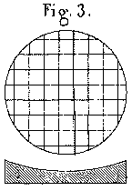
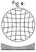
Let us assume that we have the most usual type of situation, namely that the mirror is exactly spherical in its central region, but varies towards its circumference by a gradual increase in the radius of curvature. If we submit such a mirror to the second examination process we just described, then we will see an image in which all the lines of the grid will be curved as in figure 4, where the lines bow inwards and their concavity faces outwards. The cells of the grid increase their are as one proceeds from the center to the edge, and they change in the same direction as does the radius of curvature of the corresponding sections of the mirror surface.
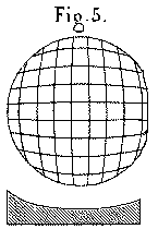
An opposite deformation of the mirror, wherein the edges of the mirror slant inwards too quickly, produces a reversal of the curvature of the lines of the grid pattern, as shown in figure 5. The result is that the areas of the cells in the image get smaller as one approaches the edges of the field. Once again, the changes in the areas of the cells of the grid correspond to the changes in the radius of curvature.
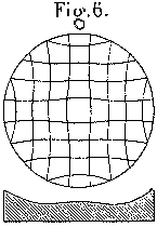
For a final example, it often happens that the edges of a mirror are reduced below the level of a sphere, while the surface of the mirror also presents a raised central region, bounded all around by a sort of circular furrow. In this case, the radius of curvature changes first in one direction, and then in the opposite direction as one proceeds from the center to the edge. This situation will reveal itself very clearly via the sinusoidity (probably a more literal word here would be waviness - Bob) of the lines of the grid (see figure 6). This arrangement produces an analogous variation in the areas of the cells of the grid.
We have taken care to reproduce, on the plate with the diagrams referred to earlier, showing the observed images, enormously exaggerated profiles of the deformed mirror surfaces. Thus, this second method of examination of mirror surfaces gives information that is very definitive and very easy to interpret. In the case where the lines produced appear to be more-or-less straight (figure 3), one cannot be sure whether or not one has in fact obtained a perfect surface. For that, the mirror will need to undergo the rigorous examination of a third and final method.
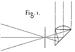
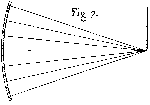
As with the first method, we need to have a point source of light close to the center of curvature, in such a way as to not mask the rays of light returning from the mirror surface. After crossing each other, these rays of light form a divergent cone into which the observer places his or her eye. Then one moves the eye forward, in front of the focal point, until the entire surface of the mirror appears illuminated. Then, using a mask with one straight edge, we intercept, or cut into, the image until it disappears completely. This maneuver makes the eye of the observer see a progressive extinction of the reflection from the mirror. In the case of a perfectly spherical mirror, the entire surface will be fully and equally illuminated until the final instant (when the illumination goes away. - Bob). If the mirror is not completely spherical, the extinction of the light is not simultaneous over the entire surface of the mirror. From the contrast of the shadows and lighted areas, the observer can perceive, in a sort of chiaroscuro (def. treatment of light and dark in a drawing - basically used as from the timeframe of the work artists were doing in the 1850's - Bob) effect, an exaggerated impression of hills and valleys on the mirror, showing what needs to be done to obtain a spherical surface. This is the effect that must needs result from the paths of the rays converging more or less precisely at a common focal point.
In the theoretical case of a perfect spherical surface, the image of the luminous point is a disk that is sharply defined and which includes all of the reflected rays. Once this is masked by our straight-edge, no light at all reaches the eye of the observer (figure 7). But insofar as this disk passes the mask at all, then, since each of its points contains rays reflected by the entire mirror surface, that surface is more or less illuminated and displays a uniform brilliance to the observer.
Let us suppose that the mirror surface is defective: the image of the point, instead of having a clear edge, will be surrounded by a luminous aureole, or ring, formed by the aberrating rays. When the correct image is masked by our knife-edge, then these rays, passing beyond, will proceed to the eye of the observer and will reveal the elements of the mirror surface that do not present themselves below the desired incidence.
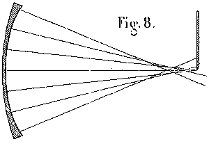
In figure 8, which represents the effects of a mirror surface with the edges raised too high, we see clearly that the knife-edge screen -- cutting the central ray forming the image - allows the rays that come from the raised edge to pass through. Consequently, at the moment when the main central ray bundle is being progressively cut off, the upper (or right-hand) edge will appear brightly lit and the opposite edge will already be blackened out, while the central region will undergo a uniform, slow shadowing-out.
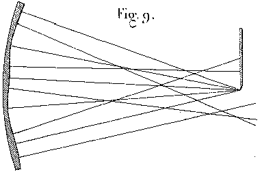
In general, if the surface being examined in this way suffers from hills and depressions distributed in some random manner, as in figure 9, all the slope faces of the hills and valleys that face towards the knife-edge screen will appear to be black, and all the slope faces that are inclined in the opposite direction will be illuminated. Thus, the appearance of such a surface will be the same as that of a matte (or more literally - 3 dimensional - Bob) surface that presents, with an extreme degree of exaggeration, peaks and troughs distributed in a similar manner, and which appears to be illuminated by an oblique light source placed on the opposite side of our knife-edge screen.
It is important to remember this rule if one wants to avoid all uncertainties in interpreting the observed results, for it often happens that the hills and the valleys seem to the observer to switch places, in a sort of optical illusion that is independent of the conscious mind. However, no matter one thinks one perceives, one can be sure to avoid this error of sign or direction as long as one takes into account the position of the knife-edge mask and that one uses that information to interpret correctly the disposition of the lighted and shadowed points.
In summary, we have now three procedures we can use to verify the configuration of concave reflecting surfaces. The first method is based on the microscopic examination of the image of a point of light, and is particularly applicable in the case where one wants to determine whether the mirror surface is one of revolution. The second, which operates by elimination, using that a lens that is very narrowly stopped-down, applies to the observation of the image of a network of square cells. This method has most of all the power to show the variations in the radius of curvature at different points on the surface. The third method, the most sensitive of all, relies on the direct observation of the surface with the naked eye of rays of light coming to a focus and passing by the edge an opaque knife-edge mask.
Observing with a microscope the image of a point; studying via a stopped-down lens the deformations in a grid; and looking at the surface with the naked eye and with rays of light that escape being cut off - these are the artifices that we call upon, one checking the other, to furnish all the desired information on the conformation of optical surfaces.
Up until now we have assumed that these procedures can only be applied to spherical surfaces, and are limited in their application to the cases where the conjugate foci are very close to the center of curvature. With these restrictions, explaining them was clearer and easier. However, considering them from another point of view, these procedures take on a much more general nature, which renders them even more important.
Making an abstraction of the mirror surface so as to consider only the reflected bundle of rays, the information furnished by these examination procedures can be applied to the bundle itself, and the characteristics which have been noted as the attributes of a spherical surface become in essence the properties of a bundle of rays which are exactly one of the conic sections.
Now, inasmuch as the quality of the images depends precisely on the final convergence of the rays of light, these instruments, no matter what type they may be, fall under the aegis of these very same testing methods. Thus, we are no longer required to observe a mirror at its center of curvature, and since our proposed goal is to construct telescopes to observe objects located at infinity, we will take the concave mirror as it leaves the hands of the artisan, and we will lead it, via a series of transformations, to a figure which will make it suitable to function on celestial bodies.
This glass mirror, without even being silvered, reflects enough light so that it can undergo all three examinations described earlier. We observe it close to the center of curvature. If it is spherical, the image of the point of light is round, clear, and distinct; the lines of the grid are straight; and we can produce a simultaneous extinction of light over the entire surface.
Once this status is confirmed, we move our source object closer to the surface of the mirror. The image naturally moves farther away from the surface, and the distance between the two conjugate foci increases, as required by the fact that in an ellipsoid of revolution there must be perfect convergence of the reflected rays at the second focus. However, since the surface has in fact remained spherical, the rays emitted from one point will not actually all cross at a single point. We confirm, by the use of the three testing methods, that there exists an aberration, such that the various sections of the mirror have shorter and shorter focal lengths the farther they are away from the center of the mirror.
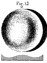
The image of the point of light, examined under a microscope, begins to be surrounded by a halo of aberration. When we change the focus of the microscope, we see this image degenerate, on one side and the other of the focal plane, into two complementary images, of which one, closer to the mirror, presents on its periphery an accumulation of light, and the other, farther from the surface, has the opposite arrangement. The lines of the grid begin to curve in such a way as to present their convexity towards the outside, as we see in figure 5. Also, the extinction of the image by the knife-edge mask produces, on the surface of the mirror, an unequal distribution of light, as we see in figure 13, which appears like a raised center and raised edges, with a circular depressed area between the two.
From all of this information, we conclude that the surface of the mirror is not one that would match the present state of conjugate foci [i.e., an ellipsoid - trans.] and that it differs from that in such a way that the radius of curvature is too short, and becomes more so as one moves away from the central part of the mirror. We now see clearly the modifications necessary to perform on this surface in order to bring it to a better state: we need to perform local refiguring so as to re-establish the lacking relationships among the radii of curvature. We will see later on that there is an infinite variety of methods of performing this refiguring.
Let us continue. In other words, let us bring the object closer to the mirror, and at the same time we will push the image farther and farther away from the mirror. The aberration will increase, along with the phenomena that reveal the magnitude and direction thereof. It becomes clear that for a spherical surface the aberrations increase along with the distance between the two conjugate foci.
But let us suppose that, when leaving the center of curvature and before passing from one station to the other, we were able to master the phenomena of aberration by performing the local refiguring that is suggested by our examination procedure. In that case, the figure of the mirror, which was originally spherical, will be gradually modified by a series of light refiguring operations. These changes will make the surface pass through a series of ellipsoidal figures, ending up, at the limit, with a paraboloidal surface. Such is the method we have followed, with success, to obtain large-aperture mirrors that give good images, without aberration, of images situated at infinity.
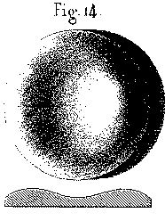
Once we have succeeded in removing all aberrations for the particular case of conjugate foci, and we have returned to one of the positions we were in previously, we observe all of the phenomena returning, but in reverse order, which gives evidence of an aberration in the cone of the converging rays. The image of the point of light, surrounded even at the focus by a luminous halo, degenerates, as one pulls back the ocular microscope towards the observer, into a bright ring of light with a center that is more or less dark. The lines of the image of the grid appear curved with their concavity facing outwards (figure 4). The surface, viewed with the knife-edge mask, appears with a trough in the central region and with the outside edges turned down (fig. 14). In a word, all the phenomena appear to be the opposite of those which one observes on a spherical surface tested at a point outside the center of curvature.
{This suggests an interesting experiment: one can bring in the knife-edge from the opposite side in testing a sphere at a particular set of conjugates and see the exact result of testing an ellipsoid properly figured for these conjugates at its center of curvature. This type of experiment has many possibilities in testing. Many variations suggest themselves.}
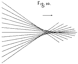
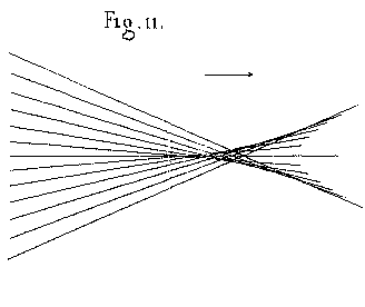
If we agree to consider as positive the type of aberration which results the most often from the disproportionate extension of spherical surfaces, then we will denote as negative the aberration in the opposite direction which results from an exaggerated or inopportune correction of a spherical figure. But, if we only consider the ray bundle as a whole independent of the apparatus that makes it converge, we can agree to denote as a positive aberration the arrangement of a bundle of rays wherein the central ones converge last of all. In this case the caustic (see figure 10) formed by the series of crossing rays has its vertex turned towards the side where the light is heading. By contrast, we will call a negative aberration the opposite arrangement, wherein the central parts of the ray bundle converge first, and wherein the caustic has a vertex pointing towards the mirror, as in figure 11.
These two states of the bundle of light rays correspond to two opposite appearances. Since one given ellipsoidal surface can produce either positive or negative aberrations, depending on whether it is functioning for foci located inside or outside the limits corresponding to its own foci, we can see that a single surface can produce, via the third examination procedure, two opposite appearances. To understand this fully, it is important to note what is the geometric direction of the figure that appears in such a situation.
Recall this: given that a surface functions in such a way as to return towards the observer a ray bundle that is free of any aberration, then that surface, no matter what it might be, when examined by method #3, will appear uniformly illuminated as if it was a plane surface. Thus, if subsequent changes occur that disturb the convergence of the rays, then the appearance of the surface will be modified so that it will appear as different from a plane surface as the altered surface differs from the correct figure. In other words, the relief of the solid which displays itself in such a case, instead of revealing the true surface of the mirror, show us the figure of the solid that is superimposed upon the correct surface.
Let us suppose, for example, that a spherical surface is examined in circumstances where it should present an ellipsoidal figure. That is to say that instead of the correct figure s (shown in figure 12) we substitute figure s' which is not correctly figured. To have an idea of the appearance which should result from this, let us put the circle and the ellipse on the same set of coordinates, and then let us construct the curve given by the changes in the differences in the y-coordinates corresponding to the same x-coordinates. This curve, which is of the fourth degree, is in fact the one which, if we imagine it rotated around the y-axis, would generate a surface that matches what we see in black-and-white shadows (figures 13 or 14) on a mirror that is examined by the third method, and when this mirror has a central zone that is a conic section, and when it has been verified as being outside the conditions defined by the positions of its own foci.
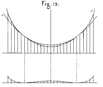
We can also see that in this figure there is an inversion of the hills and valleys, depending on whether the actual surface of the mirror is inside of or outside of the theoretical surface corresponding to the positions occupied in space by the object and the image. In this way, we begin to understand the various images presented by an ellipsoidal mirror, as these images are progressively and continuously varied, when we consider all the distances where the image that results from the convergence of the reflected rays can be formed.
Of the three testing methods which have been described in this essay, one alone, if required, could be sufficient to guide the hand which must perform the local refiguring on the mirror and cause it to pass through all of the various ellipsoids to culminate in a final parabolic surface. But if we use them all together, we are more assured of avoiding false maneuvers. Also, the various testing methods complement, rather than supplant, each other. Experience has shown many times that when all three methods are united in agreement that a particular surface has no defects, then the optical results of that mirror attain such a degree of perfection that nothing more could be desired. One could even knowingly permit a few small undulations to remain that can be seen in the third method, without the optical results of the mirror being at all noticeably different. This seems to show that sort of test achieves, regarding optical surfaces, a sort of super-sensitive reaction. The difficulty is now no longer to find the imperfections in the work on the surfaces, but to address the surface of the glass via an agent that will suffice to remove the minuscule quantities of glass which we need to remove.
Then we glue onto the previously-mentioned convex copper tool (or "ball") a sheet of paper which we impregnate with English rouge. By a prolonged rubbing on this polishing lap, we can clear up the surface of the glass, which after a while obtains a perfect polish. By working in this manner, a skilled operator can produce a surface of revolution which does not coincide exactly with a sphere, but differs from it in a direction that is favorable for correction of spherical aberration. Such a mirror may have an opening that is wider than that which corresponds to an exact spherical figure.
But when we begin to work on larger diameters, we cannot depend on such an empirical correction to be exact enough, so it is necessary to turn to local refiguring. Also, the price of the copper basins rises very rapidly as the size increases; their weight becomes quite heavy, and the increasing friction between the glass and the metal renders the work painfully difficult and diminishes the chances for success. Because of these various reasons, we have given up using metal tools, and have turned to working glass mirrors against glass tools. Henceforth, the cost of setting up shop merely consists in acquiring two disks of glass of the size and shape appropriate to the desired finished product.
For example, if we plan on constructing a mirror of 40 to 50 cm in diameter, we begin by procuring, by melting them and casting them in a mold, two disks of thick and well-annealed glass, each one with a convex obverse side. The next step is to rough them out by mechanical means so that the two surfaces have approximately the desired degree of curvature. We stroke the two disks in a in a circular fashion with the upper one, the tool, moving past the edges of the other one. We polish the obverse side of the other disk, and on the peripheral edge of each one we carve a groove which will be used to attach the cords that will aid in the work.
The two pieces of glass thus prepared, mirror and tool, are then taken to the optician's workshop and entrusted to a skilled worker, so as to be worked one against the other with all the skill needed to produce a surface of revolution. The work proceeds upon a solidly established post, a sort of pillar isolated on all sides, which bears on its center a threaded screw on which is mounted a knob or chuck which we attach to the back of both disks with pitch. Directly above this work-post, we attach to the ceiling a strong crew-hook from which we hang a helical spring that is able to support the weight of the mirror. Finally, in order to make it easier to grip the work and move it about, we screw onto the post an appendix, with a large and jutting-out border. This will serve , if needed, as a point of attachment for the cords, more-or-less taught, that will attach to the suspension spring.
The glass tool being attached to the post, we spread on its surface some medium coarse abrasive, wetted with some water. We carefully place the mirror on top of it, and we rub the two pieces one against the other, taking care to vary the movements of the glass in such a way as to distribute the action equally in all directions. At the same time that he moves around the post, the worker causes to rotate under his hand the edge of the knob in such a way that the tool and the mirror will have positions that are constantly changing with respect to each other.
Bit by bit, the abrasive is worn down, and to prevent it from drying out, we wet it constantly by sprinkling drops of water onto the parts of the glass that in their turn become exposed to view. As the work continues, the abrasive loses its cutting power, becomes finer and finer, and also becomes mixed with particles of glass removed from both disks. After a while, the worker notices that it is advisable to take the upper disk off, sponge both of them off to clean them, and to start over with new abrasive.
There is a certain art in learning how to work well with the abrasive in such a way as to distribute the emery evenly between the two surfaces, and to keep it moist enough and during a time long enough so that it can work most effectively. In unskilled hands, the abrasive is not spread out well, does not work at the glass correctly, and escapes out the sides without having performed all its duties. If that is the case, one wastes one's time in false maneuvers, one uses excessive amounts of abrasive, and the work does not advance.
The first grades of grit are designed to make the two surfaces adapt to each other. We know that result has been achieved when both pieces of glass move against each other in all directions without any preference. We then use finer and finer grades of abrasive, which are denoted in the trade by the number of minutes that they take to separate out of suspension when one mixes them up with water. These abrasives of one, two, ... forty, and sixty minutes are used in succession between the two surfaces, until they eventually give to the blank a velvety and uniform grain whose fine quality appears to have a semi-transparent and opaline luster.
If we want to obtain a surface with a certain specified radius, then it is advisable, during this long succession of different grades of abrasives, to employ from time to time a spherometer. In case we need to increase the radius of curvature, all we have to do is to attach the mirror to the post and to continue working with the tool on top. In the opposite case, simply leave the arrangement as it was to begin with, i.e. mirror on top, and to move the mirror with longer strokes.
These two methods of modifying the radius of curvature work very well, especially when one works glass-on-glass. We can understand why this is so when we consider that as soon as one of the disks passes beyond the edge of the other, the piece that is on top presses its central section upon the edge of the other. It therefore follows that the grinding action, instead of being distributed uniformly, takes place for the most part on the periphery of the lower piece and on the central part of the upper piece. One needs no more than this to explain why this unequal division of pressure and wearing away tends to increase the curvature of the glass, in the case that the concave piece is on top, and to decrease it when the positions are reversed. When we realize how to take this factor into account, not only do we no longer have to fear its effects, but we can also use it to maintain any desired radius of curvature right up to the moment when we start polishing.
With the surface haze brought to a high degree of fineness, we now need to bring it to a perfect polish. We are acquainted with several methods for polishing glass, but the one that appears to us to be the best for working on mirrors is the method of polishing with paper laps (the opthalomatic polishing pads of today are the derivative of this method - Bob) and English rouge. On the very surface of the disk which served as tool for the mirror, we use starch to glue a piece of paper whose weft appears as uniform as possible. By using a sort of glass meniscus known as a "colloir", we push the excess starch towards the edges of the glass, and we apply the paper completely and fully onto the tool surface. Then, by rubbing the glass with a damp sponge, we detach the little particles of paper, and we strip or roughen the paper in such a way as to raise a velvet-like nap which, once dried, will be effective at holding the polishing powder. We must still rub the paper with pumice, then chase it with a brush, after which we apply the English rouge with a scrap of crumpled paper. Now the polishing lap is ready.
The mirror, having been washed and dried, is placed on this lap, which touches it all over and will make the finish clear up after the very first few strokes. But before putting the mirror into motion, it is necessary to support a pat of its weight by attaching it again to the suspension spring and by using a cord that is stretched sufficiently tight. This arrangement also has the benefit of allowing us to move a rather large mass without too much effort. But what is more important is that by reducing the pressure upon the polishing lap, we slow down the creation of heat due to the friction of polishing, and we avoid to a certain extent the deformations that would result from that heat.
If, however, we neglected this precaution, then the heat generated by energetic strokes would make both of the pieces expand, and they would cease to be in contact with each other at their edges and would only touch near their center. In this case, the mirror would pivot on its center, only the central portion would become polished and would become dug-out, and the edges would remain hazy. But, by using the spring, we establish a more equal action. Even though the polishing may take a bit longer, we are ever more assured of a good result.
When the mirror seems to be entirely polished, we perform a preliminary test, and if the surface does not present any serious imperfections, we undertake to lead it towards the necessary figure for a perfect objective mirror by means of local retouching methods.
In order to perform this delicate operation in a suitable manner, one needs to have available an enclosed space where one can set up an optical testing line about four or five times as long as the focal length of the mirror. At one end, we set up the mirror in a frame that will fit into the tube of the telescope. This tube, with its prism and eyepieces removed, is carried on two trestles or sawhorses that hold it in a horizontal position and raise it to a convenient level for observations. Tables to hold the objects needed for the mirror tests can be placed all along the observation line. In addition, on a separate structure like an optician's work-post, we set up, to receive the mirror, a wooden basin whose curvature matches the back side of the glass.
Finally we prepare, for the purpose of local refiguring, a series of polishing laps whose diameters vary from about a fifth to a third of the piece that is being figured. These polishing laps are made of glass covered with paper and mounted on handles made out of wood or cork. They are used to work certain determined zones of the mirror surface and to wear them down in the same way as we produced the overall polishing of the surface. But, in order that this removal of material operates without breaking the continuity of the mirror's curvature, or, in other words, so that this refiguring takes place without creating a discontinuity or a noticeable line of demarcation with the original surface, it is absolutely necessary to prepare the polishing tools with the utmost care. For this reason, we believe it is useful to describe practical details and very precise information on this subject.
From our very first attempts, we learned that the best curve to give to the local refiguring laps was not one that exactly coincided with the curvature of the mirror: it is better to give it a small excess of convexity, because that way, the lap will contact at its center. Consequently, the refiguring will more directly address the section which one plans to work on, and it will flow into the surface on one side and the other of the point of contact in a way that is not noticeable. However, one should not exaggerate this excess of convexity in the tool, because if one does, the contact between the lap and the mirror would be restricted to an area which would no longer correspond to the area of the polisher. Finally, even if the lap has the desired curvature, it is important to pay close attention to the state of the paper which carries the polishing powder, because sometimes it happens that the rouge will move around, and when doing so, they will leave the center point of contact in such a way as to foul up the operation and to hamper the refiguring. Thus, there are several delicate conditions that must be maintained. But the art of the optician offers resources which permit us to overcome all these difficulties.
When one wants to prepare a polishing lap and to imbue it with the precise curvature needed for refiguring work, the way to do it consists of "marrying" it to a counterpart made of glass with the same diameter and the opposite curvature. Thus one has, so to speak, a mortar and pestle which one works one against the other with all the care that one would bring to the execution of a really fine surface. Once these disks have been matched against each other, it is necessary to check the curvature. For this we place the concave part on the main tool which we used for working the mirror, and whose surface has remained unpolished. By a rubbing in place we make appear a whitish line which reveals the distribution of the points of contact. For the convex polishing lap to end up touching the mirror at its center, it is obvious that it is necessary that the little concave "basin" must touch the large "ball" on its edges and to leave upon it an annular path when rubbing. As long as this result has not been obtained, we continue to modify the curvature of the laps by rubbing them against each other, taking care that the "basin" is either above or below, depending on whether we need to increase or decrease its curvature. Finally, when the check performed by rubbing the lap onto the haze of the large "ball" gives a ring-like trace which dies out about halfway to the center, we are then sure that the two disks have the desired curvature, and we can begin gluing the paper on them.
In the last resort, it could be sufficient to simply top off the paper of the polishing lap in the usual way. But just as the two pieces of glass have been used to prepare each other by rubbing glass against glass, in the same way we finish both of the laps by having undergo a similar treatment, paper against paper. We use starch to glue the papers, using the meniscus to eliminate the excess glue; we rub a wet sponge lightly all over the glass, taking care to lightly attack the "skin" formed by the original gluing; and we let it all dry out. When the humidity has dissipated, we find the paper to be well-stretched, but since it is rough and covered with little ball-like particles that were detached by the sponge, we remove them by rubbing it with a flat pumice stone, and we then chase them off with a brush. In this state, we could consider the polishing lap to be ready to go into action. However, since the paper may vary in thickness from point to point, we make it undergo a final preparation which has the effect of raising a velvet-like nap that is very good at holding rouge. This preparation consists of bringing the two papers together, working one against the other with powdered pumice that is wetted with a liquid which will not dissolve the starch. To do this, we place the polishing lap on the work post, wet it with benzene, dust it with pulverized pumice, place the "basin" on top, and we perform motions for a while as if we were doing fine grinding. Bit by bit the benzene evaporates, the pumice which had formed a sort of soup becomes once again a powder, and when we feel that the two pieces are beginning to stick together, we remove the "basin," and we repeat the whole operation two or three times.
To finish it all up, we brush both surfaces carefully and for an extended period of time, and we see the paper once again become white. But if we look at it carefully, we notice that the surface has changed for the better, in becoming covered with a uniform velvety nap whose presence always helps the action of the polishing lap.
As to the manner in which we spread and fix either the rouge or the diatomaceous earth [tripoli de Venise - transl.] which gives it a bit more bite, we have noticed that the treatment with pumice and benzene produces a uniformity that is seldom found in a sheet of paper used "as is." When the work continues for a long time, for example if a polishing lap has been worked for several hours, we see it behave quite differently depending on whether or not it underwent the last preparation mentioned above. When one omits bringing the two paper-covered laps together, it is true that the operation will work well for a while; but soon, in the central region where the most pressure is felt, the paper begins to wear, to lose its porosity, and peels off its surface layer. It becomes shiny and no longer holds the powders, which flee to the edges. In such a case, despite the excess of convex curvature of the polishing lap, its action no longer takes place in the center, but on the edges. Therefore, instead of light refiguring taking place which flows imperceptibly from area to the next, we run the risk of plowing relatively deep furrows that are very difficult to repair.
If, on the other hand, we had taken care to rub the polisher via the procedure described earlier, the rouge would lodge more permanently in the paper, so that the central region would maintain its efficacity for a much longer period of time. The center would not become smooth or lose its surface qualities, and we would not risk producing incorrect refiguring because of the weakening of its central portion and an annoying predominance of its edges.
Thus armed with two or three polishing laps of different sizes that are well-matched to the average curvature of the mirror, nothing will prevent us from beginning to refigure. Of the three examination procedures previously described, two of them will suffice to direct our work, the first and the last: namely, the microscopic examination of the image, and the direct viewing of the surface by means of rays that pass by a knife-edge mask. To determine which of these two procedures to use, we should recognize that the light source is the same for both, and that to pass from one to the other, we simply trade the microscope for the knife-edge mask.
With a preliminary test near the center of curvature, we explore the surface, and depending on the size of the local refiguring action indicated, we determine the size of the polishing lap which we should use. Then we place the mirror on its wooden basin carpeted by a piece of woolen cloth, and we begin to work.
In general, any glass surface that has remained for a time in contact with the air rebels at first against the action of the polishing lap, if one does not take care to clean it in such a way as to give it a state of perfect homogeneity. We dust it with powdered chalk, sprinkle a bit of water on that, and with a ball of cotton we create a paste all over the surface of the mirror. We let this dry, Then we take a new, loose, cotton puff, which we lightly pass over the surface. The dried white paste, which does not adhere well to the glass, comes loose, escapes over the edges, and allows the glass to reappear covered with a transparent veil. We continue to rub the glass lightly with a series of new cotton balls, and we see the veil slowly dissipate, and the surface of the glass ends up appearing pure and clean.
Even with a surface prepared in this manner, the polishing lap will still slide around at first and will only start "biting" after having passed a few times over the same sections. The points where it begins to work are distributed irregularly, here and there; there are regions where the rouge sticks and where one beings to feel the adhesion which reveals work in progress. These regions slowly enlarge, but until they have all merged into one another, the action of the polisher lacks uniformity, and there is a danger of altering the surface if one uses rouge, which has a lot of abrasive power. It is better to begin by using diatomaceous earth, which is easily spread on the paper, attacks the glass more slowly, and seems to have all the qualities desired for beginning to refigure.
When the lap is working equally well on all parts of the mirror, when it adheres equally well all over, one can replace the diatomaceous earth with English rouge, and then the work begins in earnest. This is the time to use the optical tests to find the figure of the solid of revolution that is, so to speak, superimposed on the mirror, and to plan on altering the figure by deciding which movements to give to the lap which, when repeated a large number of times and while rotating about the center, will be able to wear away the excess parts of the mirror. That motion, whatever it may be, once decided upon and adopted, should be executed without any change for about ten to 15 minutes, after which the mirror should be tested once again.
Doubtless it can happen that one has judged poorly and the movement employed gave a result other than expected. Even so, the test will provide some useful information; whereas, if one had varied the strokes several times between two mirror tests, the observed test results would not allow us to form any firm conclusions.
In any case, when the laps are well prepared, when they touch at their centers and not at their edges, when the paper does not form a skin and preserves its velvety finish, and the polishing powders do not migrate, there is no fear that the test result will display a marked disagreement with the strokes one has performed. The lap, if moved in procession on all the diameters, will assuredly produce a deepening of the central region. But if it is directed along a series of equal chords, one cannot avoid forming an annular furrow that will be further from the center the shorter the chords become. The width of the zone being worked will vary with the extent of the part that is rubbing and with the excess of curvature of the lap over that of the mirror. Polishing strokes that are directed on all chords will thus be enough to attack all the points on the surface; but in order that these lines may cross, one can also perform ellipses that are either elongated or widened. It is important to remember to check the status of the polishing lap. Also, the worker must walk all around the polishing station in a regular manner and check frequently the effect produced by each type of figuring stroke.
In this manner one will first of all produce a spherical figure, that is to say to obtain in the area of the center of curvature a well-defined image of the point of light, and produce a simultaneous extinction of the pencil of rays by cutting into that image with the knife-edge mask.
This first result, once accomplished, demonstrates the effectiveness of local refiguring and prepares the way for the work which must follow, the object of which is to arrive at a paraboloid of revolution by passing through the intervening ellipsoids. The point source of light, which was placed at the center of curvature, is brought closer to the mirror; the focus moves in the other direction; and the optical test, which just recently displayed a perfect surface, now reveals in this new position a beginning of spherical aberration. The image is surrounded by a slight nebulosity, which disappears once one forces it to come to a focus on the side towards the mirror, and which becomes more pronounced when one does the opposite: this is the sign of a positive aberration. The knife-edge mask which advances to cut off the image conveys to the surface the appearance noted earlier (figure 13). One thinks that one sees a central hill separated from the edge by an annular depression; but when one changes the distance back and forth between the knife-edge and the mirror, one finds in the stereoscopic appearance of this surface some variations that cause the bottom of the circular depression ring to approach, more or less, the center of the mirror.
A rational interpretation of this phenomenon leads one to recognize that there is an infinite number of ways to refigure a mirror so as to eliminate aberration. Thus, between the ellipsoid that is tangent to the center (figure 15) and the ellipsoid tangent to the edge of the spherical surface (figure 17) there is an infinity of ellipsoids which have a surface of contact with the actual surface (figure 16); their diameters can take on any value smaller than the diameter of the mirror.
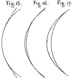
Among those surfaces, towards which one should we strive? That depends on the dimensions of the mirror. When its diameter is not greater than 25 or 30 centimeters, it is best to use the strokes that are easiest to perform, namely those which leave the edge zone alone and work primarily on the central portion of the mirror. But when the mirror becomes larger, it is better to be guided by other considerations, and to search for the refiguring methods that will lead one to remove the smallest possible amount of glass. One therefore divides the refiguring between the edge and the center, and does nothing to the zone that corresponds to the circle of contact, as one can see in figure 16. In any case, one ends up by effecting an apparent leveling of the surface and at the same time destroying the aberration which surrounded the image of our point source of light.
This result being verified, we repeat the same operation for a more advanced position of the conjugate foci; the mirror changes by taking on a more and more pronounced ellipsoidal form. Passing this way from station to station, the two foci proceed in opposite directions, and they show, in increasing the distance between them, that the ellipsoid is undergoing a corresponding elongation.
Finally, the image of the point, which had been advanced farther and farther and is still free of aberration, finds itself at the very end of the experimental line laid out earlier. At this point, with a final refiguring, we need to push it all the way to infinity while still being fully corrected. The longer the experimental line, the less this last step will appear to be hazardous. Nonetheless, we need to stay within practical limits. We have assumed that in our operation, the distance between the two farthest workstations is at most equal to five times the focal length of the mirror. Let us preserve this assumption, and let us show that our final refiguring operation can still be subjected to a rigorous exam.
When the image of the point of light has reached the end of the line, the point source itself is still at a certain distance from the principal focus of the mirror, and since the latter point is half way to the center of curvature, its position can be determined. Let us call F the principal focal point, and F' the present position of our point source of light. We will call F'' one of its previous positions, with the condition that F'F'' will be equal to FF'. By virtue of the previously explained principles on the progress of positive and negative aberrations, it so happens that if we bring the point source to F', the appearances will appear as if the mirror had become parabolic, and that the point source had remained at F.
Let us examine now the relief of the figure that appears now, and then, while bringing the light source towards F', let us try to reproduce this relief by modifying the surface with a final refiguring session. In this way, we can make the image pass to infinity without any aberration, and we can impart to the mirror a figure that is very near to a paraboloid of revolution. But even if it is impracticable to go and observe the image at infinity whence we have pushed it, nothing could be easier than to verify the result we have obtained by switching the object and its image. To do this, simply take as a target an outside object, located at as large a distance as one desires, and observe it with the mirror mounted in a Newtonian telescope. The image must then show itself to be free of aberration, and to show diffraction lines around the object. If this object is a point of light, or if it takes on the appearance of a square grid, then the three testing procedures described earlier become applicable at the prime focal point. If any perceptible defects remain that escaped our last refiguring session, there is still time to do another one and to make the defect disappear.
To sum up, the method we have just described consists of subjecting our surfaces to optical tests, and then modifying them via hand refiguring sessions until they appear to have no more defects. The nature of the situation has permitted us to initiate, on the one hand, various testing methods, and on the other, various methods of working the surface of the glass. These two procedures allow us to arrive precisely at the result we were attempting to obtain. But if the testing procedures are not sensitive enough, or if our refiguring methods were less delicate, then this method would have failed. However, our experiments have been quite successful.
Let us also suggest that our methods might not be applicable to metallic mirrors, for it has not been shown that the crystalline alloys which make up those mirrors up until now are capable of bearing an indefinite series of refiguring operations as do glass mirrors with polishing laps.
But even though we have failed in trying to extend to metal mirrors the benefits of local refiguring, this is not a great loss, because even if it were successful, the benefit would only be temporary. The advantage would be compromised from the moment that the metal polish was altered under the chemical influence of the air. By comparison, once a curvature is made in glass, one can consider it to be permanent. The alterations and tarnishing that will occur with time only affect the layer of silver metal that is deposited on the mirror afterwards by an operation that can be renewed indefinitely.
The method we have just described, and which has been carried out a great number of times, always results in bringing optical surfaces fairly quickly to a degree of perfection which can not be surpassed. When one arrives at that point, one needs to ask whether the impossibility of making any more progress lies in the imperfection of our procedure, or whether it lies in the fact that one has reached the goal of creating a perfect surface. For us the question is not in doubt, and we will not hesitate to consider as perfect a surface which acts as far as we can tell upon light as would a mirror that corresponds precisely to the figure required by optical theory.
When a surface approaches this degree of relative perfection, one can watch an ensemble of characteristics intervene which, once understood, can serve as a guide for the worker and give notice that the work can be considered finished. At the same time as the defects disappear that are revealed by the various optical testing methods, the image, as seen under a microscope, produced by such a surface takes on a particular appearance that pleases the eye and does not disappear even when uses great enlarging powers. This remarkable appearance comes from the fact that the image is being formed by a grouping of correctly circular elements. Each of these elementary disks is in fact surrounded by a certain number of rings; but since the latter have rapidly decreasing intensities, the central disk has so much more brightness that it has the preponderance of the precise outline of the contours of light. Of the various rings that surround this disk, one can normally only see the first one. And since a dark interval separates them, the result is that this first bright ring does not bring any appreciable confusion to the image. Also, since it is superimposed on itself, it merely draws a pale belt that runs around, and is parallel to, the brightest contours of the image.
The theory of diffraction explains this phenomenon, which implies that all the rays of the convergent light come to its vertex almost completely in phase vibrationally. If we could substitute a surface that is rigorously exact for the approximate surface obtained via our experimental methods, the rays would arrive at the vertex in perfect accord. But the point of light - or rather, the narrow disk - formed by their coming together would still be surrounded by no less rings than before. Therefore there is no practical point in trying to push surfaces beyond the degree needed for the appearance of diffraction phenomena.
When these phenomena become apparent at the focus, or in other words, when the image of a point formed by the entire uncovered mirror appears in the form of a disk surrounded by rings whose brightness decreases rapidly, then we can be assured that such a mirror, aimed at any sort of object, whether on earth or in the heavens, will produce good images, and will give optical results corresponding to its diameter.

To judge the result with certainty, and to express those results in a form less vague than one normally uses in ordinary language, we should mount the mirror in a Newtonian telescope and aim it at a distant target. We should arrange this target is as to provide details placed at the limit of visibility. We construct these test targets by inscribing on a sheet of ivory a series of divisions arranged into successive groups, where the millimeter is divided into smaller and smaller parts. The thickness of the lines engraved should vary from one group to the next in such a way that the darkened portion has the same area as the interval that separates them (figure 18). If one views such a target placed at a distance, or if one observes it with too weak an optical instrument, then the different groups appear merely to have a uniform light gray color. But if one decreases the distance or uses more powerful optics, one sees that the groups that are the farthest apart resolve themselves into distinct lines, while the rest remain blurred.
When we increase the enlargement and illuminate the target sufficiently, we can conclude that in the groups that uniformly gray, the blurriness of the lines cannot be attributed to the weakness of the eye. It must be entirely because the instrument resolves one of the groups and does not resolve the next one. In verifying in this way which of the groups is so close together as to be located at the limit of visibility, we obtain positive proof that the instrument can separate the parts that are separated by a certain angle, and cannot separate those that are closer together than that. It then follows that the ability of the instrument to penetrate the details of observed objects, or what we could call its optical power, is inversely proportional to the angular limit of separability of the adjacent divisions. The definitive expression of this optical power is the quotient of the distance to the target, divided by the mean interval between the finest visible divisions.
To this sort of test we have submitted a great number of mirrors of all sizes and of all focal lengths. These experiments have led us to a general expression of optical powers which is remarkably simple. We have found that this optical power is independent of focal length, that it varies only with the diameter of the mirror, and that it works out to about 150,000 units per centimeter of diameter. Without having done as many experiments on achromatic objectives, we have nonetheless discovered that, when we reduce them to their active surface diameter, they obey the same law, and that if the diameters are equal, then both lens and mirror are capable of having the same optical power.
This fact, which appears to be henceforth well-established, naturally leads one to search in the physical make up of light, and not in the imperfections of our instruments, for the obstacle which limits the extension of the effects already obtained. No matter how the optics are constructed, these instruments, as long as they approach perfection, tend to display optical powers that are in a constant ratio with the respective diameters of the ray bundles that are transmitted. One can not refrain from considering this ratio as a physical constant whose value expresses the aptitude of light for forming detailed images. In taking a millimeter as our unit of length, to which we normally relates the wavelength of light, we find, according to our experiments on optical powers, that the value of this constant is the number 1500.
This optical constant of light is intimately linked to the wavelength of light and is inversely proportional to it, so that it varies for light of different colors. This means that rays that are more easily refracted [i.e., shorter wave length light, such as blue light - trans.] produce the greatest power of definition. Experiments have confirmed this numerous times, especially via the clarity of microphotographs taken with ultraviolet light.
In general, physical constants have a reason for their existence which flows directly from the nature of the agent whose physical properties are being defined. Evidently this number 1500, which expresses in some way the separability of points of light, proceeds from the number of light waves contained in a unit of length, and multiplied by a coefficient that depends both on the procedure used to determine optical power and also on the physiological aptitude of the retina to perceive different impressions.
It may be feared that while trying to give rise to the notion of optical power, will unwillingly provoke optical workers to announce impossible powers. But anything is liable to be distorted. To help put other observers on guard against illusory observations, we have taken care to explain precisely the way to obtain comparable measurements. We also maintain that there is an absolute limit to how high the magnification can be raised in practice by any optical instrument.
Nonetheless, we need to reserve the case where our instruments will be tested on the sky.
When the weather is very fine, it can happen that the observation of double stars with equal magnitude reveals an optical power that is higher, even up to twice the result that one would conclude from terrestrial targets. Here is an explanation for this possible anomaly. With our terrestrial target, the details we are trying to distinguish are equal spaces, alternately black and white. That was a necessary arrangement so that we could always fall back on identical conditions of lighting and observation. But this equality of black and white is far from being the best arrangement as far as one's ability to resolve detail is concerned. In the image of such an arrangement, the width of the white areas equals their geometric area increased by the apparent diameter inherent in the width of the elementary [Airy? -- trans.] disks, so that at the moment that these white areas begin to merge, they have a width that is twice the one they would present if the white parts were infinitely small in comparison to the black parts. However, in the sky the real dimensions of double stars are infinitely small in relation tot he space between them. Thus, the width of the image of these stars is reduced to these elementary disks, which makes it so that their angular separation, with a homogeneous atmosphere, is easier than with the ivory target. We are not yet able to state how much higher the optical power determined via double stars is than that obtained by viewing the ivory target, but we are sure that the difference is considerable. A 33-cm telescope, which gave us our first opportunity to witness the fact that the blue companion star of Gamma Andromedae is a double, only had a computed optical power of 400,000, which indicated that it should theoretically only have been able to resolve one half arc-second. However, it is estimated that the angle of separation between the blue binary stars of Gamma Andromedae is 4/10 of an arc-second.
We have stated, in a general way, that in a perfect instrument the optical power is independent of the focal length. If we want to understand this fully, then we should analyze the constitution of the images of objects by following the theoretical deductions step by step. In a perfect image, the number of distinct points clearly depends on the size of the elementary disks that represent the different points of the object. Since these disks are surrounded by a dark circle which is the geometric locus of all of the points where one-half of the bundle of light rays is out of phase with the other half, it follows that the size of these disks depends both on the wave length of light and the angle of convergence of the rays at the extremities. For a fixed wave length, and for a constant diameter of the base of the bundle of rays, the width of the image varies with the focal length. But since the size of the elementary disks varies noticeably in the same ratio, the result is that the number of different parts does not change. Because of this sort of logic, we have been led to construct short-focal-length telescopes without fear of affecting their optical power.
But if this optical power only depends on the useful surface of the objective, then one should expect that in reducing the active surface of a good mirror by using a diaphragm or stop, one should reduce the optical effects of the mirror in proportion. This result, which was foreseen, seemed to be so contrary to what ordinarily occurs that it seemed wise to us to check it directly.
This experiment has been repeated several times on telescopes of all sizes, and it has now been confirmed that by local refiguring one can bring mirrors to such a degree of perfection that they cannot be subjected to any diaphragm or stop without losing some of their optical power. From this flows a new character and a very simple test that can be used to check the quality of a telescope; for depending on whether they gain or lose in optical quality as they are stopped down, we can judge in a decisive manner how nearly they approach perfection.
All of these facts are additional confirmations in favor of the wave theory of light. In the former theory, the focus is simply the point where independent rays cross each other; the more rays, the brighter it is, but the smaller the probability that this crossing will occur at a unique point. But according to wave theory, the focus that forms in a homogeneous medium is the center of spherical waves with the same phase; the longer the wave length, the better this center is determined. The rays we consider geometrically have no individual existence; they are simply the direction of propagation of waves. Among these supposed rays that a surface is supposed to regroup at a focus, all are special: those that vibrate in phase constitute a limited focus; those that because of a surface imperfection have undergone a difference in travel path that incapable of putting them out of phase, are pushed a certain distance away from the others without ever being able to come closer to them than a certain limit. There is a discontinuity between the waves that are in phase and those that are out of phase, and this discontinuity reveals itself by the presence of a black circle that stands like a rampart around the large center of the effective rays. However, if by refiguring one is able to bring back those deviated rays, one will find that they will never penetrate that dark space; they avoid it and cross it as the effect of an unstable equilibrium, only to reunite themselves by pressing themselves against the group of in-phase rays.
This discontinuity in the path of the rays that are called upon to become effective, explains a phenomenon whose singularity has often struck us. When a surface, even a very incorrect one, is merely one of revolution, the phenomenon that one notices during the various focusing maneuvers consists in the fact that, in a greater or smaller area on either side of the point of best focus, one notices the presence of an image that remains clear, while still detaching itself on a background of ambient light. Assuredly, if the deviated rays could approach the focus closer and closer, this phenomenon would not appear, given that the successive foci formed by the different zones are continuously linked one to the next. But since in reality every focus is limited and essentially preserved from the confusion by a black annulus, whatever zone forms an image in the plane being observed in, is bounded on either side by inactive zones which assure to their own images the ability to dominate over the lighted background formed by the brusque dissemination of other rays.
The same explanation accounts for the phenomenon of doubling which occurs so frequently with large instruments. Opticians assume that doubling of images is due to an accident in their work which divides the surface of the objective into two discontinuous regions separated by a "parting" ridge. This explanation has no foundation, because one never finds an intersection between two regions, nor any surface discontinuity. In reality, image doubling is a result of the superposition in the converging apparatus of two distinct defects. It happens every time that the objective is marred with a positive or negative general aberration and also presents two central rectangular sections with unequal curvatures. We have discovered, when discussing the paths that have been followed, that in such a case there are formed in the converting ray pencil to excentric groups of active rays, and that the central rays that remain out of phase become inactive in their perpendicular direction. We can produce, at will, the phenomenon of image doubling by choosing a mirror affected by aberration and then compressing it along one of its diameters. When the aberration is positive, the doubling occurs perpendicular to the compressed diameter; if the aberration is negative, the doubling is parallel to that same diameter.
If we consider now that this ring surrounding the focal image of each point of light, and which works so powerfully to give definition to images, also has the effect of rejecting the rays that would harm the useful rays at a noticeable distance, then we can judge how much its presence must favor the application of our third method of examining optical surfaces. That method is precisely designed to establish how much those rays depart from one another, by the interposition of an opaque knife-edge screen.
When after doing refiguring all the harmful rays have returned into order, one can still not conclude, as we have already stated, that the reflecting surface has attained geometric perfection in all its rigor. However, the result is that the remaining defects are contained within limits which one can determine by very simple calculations. The formation of an exact focus implies the rigorous concordance or the absolute equality of the paths traveled by all of the rays. If a focus forms that appears perfect, it is not exaggerating to say that all the rays are in phase to at most one-half wave length, because those that were out of phase by any more than that would be rejected outside the first black ring, and would end up reinforcing the exterior rings. Now the average wave-length of light is about half of a thousandth of a millimeter, and a half-wavelength is a quarter of a thousandth [ of a millimeter]. But if any part of the surface is in error by a certain amount, then this error will act upon the paths traveled, whereupon it will be doubled by reflection. And since we have assumed that all of the rays are in step by less than one-half wavelength, it results that all the points on the actual physical surface of the mirror approach the theoretical surface by less than one eight-thousandth of a millimeter, or roughly one ten-thousandth of a millimeter.
Independent of the size of the surfaces, that is the degree of perfection which comprises local refiguring pushed to the point where we realize foci that are physically perfect. If we use the spherometer to test quantities of this order, it can only respond with uncertainty; how then can any machine working the glass attain them? We must therefore work by hand. But even the human hand cannot work alone; it must constantly be guided by the hints from the light itself.
To sum up, in this section, devoted specially to optical power, we have established that there is a group of characters by which one can tell that a surface approaches perfection. When such surfaces are subjected to examination, they cease to show any perceptible defects. The images they give take on a good appearance that is maintained under very strong enlargement, the contours are clear and can be seen accompanied by pale diffraction fringes. Also, when one applies a diaphragm stop, one notices that no portion of the objective can be masked off without a comparable weakening of the optical effects.
In order to give a numerical value to the concept of optical power, we consider it to be inversely proportional to the smallest angle under which one can observe the separation of the smallest details visible in the focus of an instrument. We took as our test subject a distant target formed by contiguous, alternating black and white spaces, placed at the limit of visibility on account of its distance from the telescope and the distances between the black and white areas. We expressed the optical power as the quotient of the distance from the target to the focal point of the telescope, divided by the mean separation between homologous sections in the target.
After a large number of experiments performed on mirrors and lenses of all sizes and focal lengths, we have determined that the optical power depends only on the diameter of the effective surface. Consequently, this power and this diameter are in a constant ratio characteristic of white light, and which expresses in a general way the delicacy of the agent or its virtual power of separation.
If we take the millimeter as our unit of length, to which the wavelength of light is normally linked, we find that this optical power is a number approximately equal to 1500. From this, we can deduce by a simple proportion the maximum optical power of any objective of any size.
We insist that there does really exist an absolute limiting power, so as to establish that which one should be able to expect from a telescope of any given size, and also to deter manufacturers from claiming to have obtained or trying to obtain optical results that are simply impossible.
Today we are aware of a number of different procedures for reducing silver onto the surface of polished glass. Originally, these procedures only were intended to form a sort of silvering on the reverse side, like on a looking-glass. No one bothered about the uniformity of the thickness of the deposited layer, nor about whether it adhered well to the glass, nor about the extent to which it was polished on its back side. No one worried about speeding up the reaction by raising the temperature; the only concern was cost.
When applying this process to optics, the cost of silvering is pretty much insignificant. We have all the latitude in the world to satisfy conditions that take on a major importance at the moment that the metallic layer, deposited by chemical means, is called on to reflect light by its exterior surface, to form images, and to reproduce precisely the underlying glass surface. The Drayton process, which uses very pure alcohols as solvents and uses as reducing agents very expensive balsamic essences, is the one which we employed at the time of our first experiments. After three years of experience, it still seems to us to be the best method. It acts at ordinary temperatures, and the layer of silver which it forms on the glass is already reflective when it leaves the bath. It presents a uniform thickness and has shown itself to be sufficiently adherent to support a prolonged rubbing by a piece of leather reddened with iron oxide. Polished, it reflects about 75 percent of the incident light.
We have not changed anything in the procedure itself; but since we needed to make a novel and very delicate application of it,, we have been led to regularize some of the details of the manipulation, to change slightly the proportions of the elements that enter into the formula, and above all to study the empirical influence of each ingredient by either adding a bit more or a bit less. This was the only way to go to arrive, in all circumstances, at the best mixture of the variable products which one can find in commerce.
There are three operations which must be executed in turn on a glass mirror in order to give it the lively metallic brilliance of silver: the preliminary preparation or cleaning of the surface, the formation of the silver deposit, and the polishing of this same metallic surface.
The preparation of the glass surface which is to receive the silver layer exercises a great influence on the manner in which the reduction will operate. The silver-bearing solution, which has the special property of reducing itself when in contact with solid and polished surfaces, acts faster and forms a layer that sticks better and in a more homogeneous manner when the surface is more free from foreign bodies on its surface layer. For a glass surface to present this degree of chemical purity, it is not enough that is appears to the eye to be perfectly clear and shiny. When cleaning it, we must use measures whose efficacity have been demonstrated to need no other verification than that of the silvering operation itself.
Whether the surface has already been silvered or not, we begin by wetting it with a few drops of pure nitric acid, which we then spread around quickly with a wad of cotton. Then we rinse the surface with water, and wipe it with a dry cloth. In this state, the surface only retains on it that which comes from the water itself and the cloth we used to wipe it off. To purify the surface, if not completely, then at least to fix it uniformity, we powder it with pulverized Spanish chalk, add enough distilled water to form a paste, and spread it all over using another wad of cotton. We leave the glass to dry on its back long enough for the water to evaporate; the soluble substances will fix themselves in the chalk, which will serve as a carrier. Now it is the turn for this chalk to disappear. We take some carded cotton [in the 1850's, people were still carding, combing, and spinning cotton and wool by hand - trans.], without squeezing it, and with light rubbing we attack the layer of white chalk. The chalk will separate from the surface while still leaving it covered with a uniform veil-like haze. When this haze is removed, the glass will be left in the best state for being silvered. We form a new wad of cotton by superimposing regular layers of cotton taken from a card, and we rub lightly all the parts of the surface, taking care to remove the surface layer of cotton as soon as it is full of chalk. In this way, the haze which covered the glass slowly dissipates without any discontinuities or lines of demarcation being visible. Now we feel the cotton sliding on a clean surface. This is the moment to take a firmer cotton wad and to work it energetically on the glass while paying special attention to the area near the edges. After a while, when we feel that the surface cannot improve, we brush away with the cotton the dust that has a tendency to attach itself to the glass because of the static electricity produced by the rubbing. Then we lay the glass down while waiting to immerse it in the silvering bath. But before describing the latter operation, it is wise to give the formula to follow for preparing the solution.
The composition of the silver bath is fairly complex. Its primary ingredients are water, alcohol, silver nitrate, ammonium nitrate, ammonia, galbanum gum ***[donno what this is-perhaps gum arabic? Comes from Persia, and is in the umbelliferae family], and essence of cloves. Before entering the final bath, these elements are united in temporary solutions, whose compositions follow herewith:
From all the products previously mentioned we then form a mixture composed as follows:
First we dissolve the silver nitrate in water, then we add the ammonium nitrate, which acts to prevent the solution from precipitating when we add the free ammonia. Then comes the alcohol, and lastly the tincture of galbanum. In other words, the substances should be incorporated one with the others, following the same order one sees in the formula.
The resulting solution promptly turns brown and forms a precipitate that deposits itself in a couple of days. We decant the clear portion and store it in darkness, where we keep it for use labeled "standard solution." This solution, inactive by itself, has nonetheless a great tendency to reduce itself on contact with glass as soon as one adds three percent tincture of cloves (solution #4).
Meanwhile, the deposit which forms rapidly at 15 or 20 degrees Celsius, despite its good appearance, does not have all the consistency needed to resist a final polishing. The addition of four or five percent pure water, which slows the reaction, also gives the silver deposit greater solidity. If we add too much water, the solution will become too slow-acting, and the barely-formed layer of silver would stop in its development at such a degree of thinness that it could never acquire its normal coefficient of reflection. Thus, it takes careful observation and experience to help us decide precisely what quantity of water one needs to add to the standard solution to obtain the best deposit of silver.
The same concept holds with the ammonia, which, entering the mixture in very small amounts, is almost never added in precise enough quantities on the first try. If there is not enough ammonia, the solution works slowly, and then one has to decide whether this slowness comes from an excess of water or from a lack of alkalinity.. When it's the ammonia that is lacking, the deposit of silver when taken out of the bath presents a very pronounced violet color and seems to be covered with a whitish veil. If on the contrary there is too much alkali, then under the influence of the cloves, the solution reduces itself en masse and to the detriment of the elective action of the walls (???), and the deposit on leaving the bath seems tarnished and covered with a sort of dark gray crumbly layer. The correct proportion of ammonia is that which gives the deposit a rich golden color tending towards rose, with the formation of a light ash-gray veil.
But while the addition of water happens by hundredths, the adjustments of pure and concentrated ammonia must never be more than by the thousandths. If by mistake one has added too much ammonia, the solution is not completely lost, because it is easy to repair it with nitric acid. The only result would be a slight increase of ammonium nitrate, which does not exercise a harmful influence on the deposit. To sum it up, it is by the water and the ammonia that one adjusts the solutions correctly. To avoid losses of time, one would do well to prepare in advance large quantities of standard solution, to pour them together in a single flask, to treat them en masse for final adjustments, and to store them hermetically sealed under the label of "tested solution."
One should never try to silver an important piece unless one has an already old and previously-tested solution on hand. The operations takes place for large pieces in copper basins that have been silvered on the inside by electrolysis, so that will not be attacked on contact with silver nitrate. The diameter of the basin must be about 3 to 5 cm larger than the piece being silvered, and it must be deep enough as well. For mirrors of small dimensions, one can simply use porcelain platters that one can find in commerce.
It is necessary to finish off the back of the mirrors with a polished surface, and to leave this surface free of any obstacle that would impede the access of light and would prevent one from watching the progress of silvering. If a mirror is large enough that one cannot handle it securely by holding it only on the sides, then it is necessary to carve a groove along the sides where one can fasten two handles made out of cord, attached solidly by several turns of string. One must also prepare three small pieces of wood, or better yet whalebone, narrow and beveled that one will slide under the edge of the mirror immediately after its immersion in the bath, to prevent it from touching the bottom of the basin. This will also provide some space for the circulation of the liquid. Finally, when one works on mirrors that are fairly heavy, we make the basin sit on a plank of wood that has curves formed in it to act as sort of a cradle. In any case, the operation should take place in broad daylight and in a location that has been brought to a temperature between 15 and 20 degrees Celsius, because light and heat exercise an absolutely necessary influence on the reduction of silver.
Even if the surface to be silvered has undergone a perfect cleaning, if the immersion in the bath is not done with all the required precautions, various sorts of blemishes can occur in the silvering, or else unevenness or halting of the process. The basin having been cleaned with Spanish chalk, one prepares, to pour the solution into, a large cone of glued paper that one puts into a funnel like a paper filter. We cut a hole about 2 or 3 millimeters in diameter in the point of the paper cone for the liquid to flow out of. This hole is maintained 3 or 4 centimeters above the bottom of the basin. At the very moment we begin operating, we mix, while agitating them in the same vessel, the tested solution and the 3 percent of tincture of cloves that determine the reaction. Of this we pour a small amount into the basin and we spread it around with a wad of cotton; then, we pour the rest into the funnel, which flows out the hole and renewing its surface, and when flowing it only encounters walls that have been already wetted. We then take the mirror by its handles, hold it obliquely in order to make it firstly to rest at an angle of its principal face, and we lower it with a uniform movement which determines the progressive invasion of the layer of liquid. We slide the three holders into three equidistant points so that they will keep the mirror from touching the bottom, and we place the basin on its cradle while exposing it freely to the full light of the sun. From this moment on, one simply must stir the liquid gently while leaning the apparatus from one side to side, and also must turn the basin around by half-turns.
In the first few moments before the reaction begins, the surface submerged in a liquid that is less refractive than glass gives to exterior objects a visible image through the thickness of the disk. But soon, under the influence of the first deposits, this image weakens, takes on a brownish tint, and almost completely disappears. Then it suddenly reappears with a metallic shine, whereby one deems that the reflection has changed its nature. The elapsed time between immersion of the mirror and the reappearance of the reflected image is important to note, because it serves as a guide for the total amount of time for the reaction, which generally requires only about five to six times longer to produce a complete silvering. In normal conditions of temperature and light, the reappearance of the image occurs five minutes after immersion, and after a further 20 to 25 minutes in the bath, the layer of silver acquires all the thickness needed.
When one deems that the deposit has thickened sufficiently, one should take the mirror out of the bath, let the liquid drip off until it threatens to dry out, and then put it into a second basin containing ordinary alcohol diluted by water to a level of 67 degrees on the alcohol meter of Gay-Lussac or 25 degrees on the densimeter of Cartier. We stir the liquid until the drops coming off are no longer colored, and we then transport it into a third basin containing ordinary filtered water. A certain amount of stirring, without letting the surface emerge into the air, will hasten the dissolution of the alcohol into the water, but it is always prudent to prolong this washing beyond the six to eight minutes that are strictly necessary.
The mirror is finally put into distilled water, and from there placed on its edge in an almost vertical position in contact with a cloth, where we let it dry. When the operation has been conducted properly, we see the water level pull back and leave uncovered a surface with a golden-yellow color, tending towards rose, and covered with a light ash- gray veil. When examined by looking through the layer of silver, one only sees objects that are brightly lit, and they appear with a strong blue color.
Now we need to remove this light veil which colors the silver and reduces its reflectivity. Experience has taught us that it is necessary to start by rubbing this surface with a chamois skin that is placed over a soft wad of carded cotton stuffing. One must refrain from putting any polishing powder on the chamois leather, understanding that this preliminary rubbing is mostly intended to press down upon the silver deposit, to crush its inherent velvety structure, and to impart to it a solidity which will permit it to withstand a full polishing.
There is a singular phenomenon which never fails to happen and which seems to show that under the soft pressure exercises by the skin, the layer of silver modifies it constitution. The transparency which it displayed to a small degree when leaving the bath, diminishes noticeably during the rubbing; the transmitted blue color becomes darker as if the very small interstices capable of transmitting white light had just been obliterated because of the crushing of the gaps. After having been polished, the layer of silver, which has actually lost rather than gained material, in fact transmits less light than previously.
When the untreated chamois skin has produced its effect, one takes a second one set up the same way, but impregnated with fine English rouge that has been washed with the utmost care. We move it with circular strokes all over the surface, paying particular attention to the edges, which always have a tendency to remain behind. Bit by bit, the silver recovers it whiteness and gains a polish which reproduces that of the surface it rests on. This is the polish of the glass in its perfection, increased by the intensity of the metallic reflection. During an hour or two, depending on the extent of the surface to be polished, the mirror's reflective qualities increase steadily. But later, once the reflection of objects that are in the shade gives a handsome black image, one must stop prolonging this treatment which otherwise would alter the texture of the thin layer of silver.
This is all the details of the process that we have followed for regularly silvering glass mirrors, without the surface of them displaying the slightest visible change under the different (optical) examination procedures.
We do not claim that all these precautions are strictly indispensable for succeeding in producing a silvering good enough for use; but having many times observed that only rarely does one resign oneself to accept even the slightest defects that impair the uniformity of a good surface, we have understood that we should indicate all of the methods, whatever they may be, to obtain mirrors without blemishes.
After its invention by Newton, the [reflecting] telescope has been redesigned several times by various scholars and artisans. The image formed at the focal point of the mirror in a reflecting telescope does not present itself in a position that is as easy to observe as in a refracting telescope. The various ways that have been devised to make the image of a reflecting telescope more accessible are based on different methods that could be the subject of some debate. From the outset, Newton took the wisest path, which consists of projecting the image out to the side, perpendicular to the axis of the tube, and of observing the image via an eyepiece that is mounted on the exterior of the telescope tube. The cone of the convergent rays of light is reflected by a flat mirror that forms a 45-degree angle with the axis of the tube. The mirror is, of course, located in front of the focal point, at a distance at least as long as the radius of the tube.
In order to avoid the losses of light transmission that would be caused by a second metallic reflection, telescope makers have tried to replace the diagonal mirror by a prism with total internal reflection, which would act on the bundle of light rays without causing any other losses except those from absorption in the prism and from partial reflections from the two perpendicular surfaces. However, in large telescopes such a prism would have to grow to such a size that it would be almost impossible to make. In short-focal-length instruments, such as we had in mind, this prism would have to assume even larger dimensions, and would threaten, by its own internal imperfections, to cause all kinds of distortions in the images that would be formed.
We chose a different method, in placing a small prism in the path of the light cone, close to the focal point, which would leave the image inside the telescope tube. We then put a composite lens with four elements in the path to bring the image outside the tube and make it visible. Whatever the objections observers might have against lenses composed of four different pieces of glass, one cannot ignore the many advantages of this arrangement. Actually, it solves quite a few problems. First of all, by using a prism only as large as needed to not restrict the field of view, one obtains total internal reflection. Secondly, by being small, it is relatively easy to have a high-quality prism with good internal homogeneity and excellent workmanship on the optical surfaces and their angles. The final advantage is that the four-element lens delivers an upright image.
On the other hand, since the composite lens was designed and engineered for refracting telescopes and binoculars, when one links it without modification to short-focus parabolic mirrors, one tends to find a certain amount of spherical aberration. In other words, in this eyepiece, two of the pieces of glass in fact play the role of objective lenses and begin to display the imperfections found with spherical curves. The remedy for this problem is quite simple: one simply performs an additional optical refiguring, which, while sacrificing the mirror image, results in a corrected image vis-a-vis the entire optical system of the mirror and the objective parts of the lens. Using this method, the mirror and the system of amplifying lenses are invariably linked together, and to change the enlargement power of the telescope, one merely has to change the system of the two other lenses, which is similar to the arrangement in an ordinary astronomical eyepiece. Thus, it is no longer actually required to construct mirrors that are exactly parabolic. We feel it is better to end up with an experimental mirror surface, which has purposely the property of acting in concert with the magnifying lenses in the eyepiece, to assure the production of a perfect image.
In speaking of the formation of images, the considerations which we have developed have helped us to evaluate the degree of precision required in performing local refiguring of the mirror. These same considerations determine the limits beyond which accidental deformations of the mirror would begin to harm the quality of the images. If we want the images to appear cleanly, it is required that in all the positions held by the mirror, the various elements of the surface must stay fixed among them to a precision of one ten-thousandth of a millimeter, because any relative displacement which exceeds this minimum quantity would place some of the rays of light out of phase with the others, and would throw them out of the effective group. One can understand from this the extreme importance of the precautions to be taken to remove from the mirror all forces that would tend to alter its figure.
When the mirror is placed at the end of the tube and the instrument is obliquely directed towards a point in the sky, the weight acts along two perpendicular component vectors, one which tends to compress the mirror in the direction of a diameter seen in a vertical plane, and the other which presses the mirror against the resistant parts that its back rests on. These two components, which vary in a sense contrary to the direction of the instrument, must be combated separately. The one that compresses the mirror on its edge can only by opposed by the rigidity of the material, which, under a given weight, takes on a maximum value when one finishes the back of the mirror with a sufficiently convex form. We have found it advantageous to shape the back of the mirror along a curve such that the thickness doubles from the edge towards the center, where it takes on at least one-tenth of the diameter. This is only a palliative which does not radically prevent deformation, but in reality this component of the weight along a diameter is not too much to be feared, since this deformation diminishes as one raises the telescope towards the zenith, and since the flattening which can occur over the totality of all the convergent ray bundles can be corrected easily by using a cylindrical lens.
The other component, whose intensity varies in an inverse manner with the first one, exercises a much more annoying influence on the image. As the instrument is raised up, the solid parts on which the mirror presses make the corresponding parts of the mirror push forwards, and cause undulations which show themselves at the focus via long trails of light. It is necessary to get rid of these local pressures and to spread them out uniformly over the entire surface of the back of the mirror. (To achieve this) we attach to the mirror mount a slab of wood, and we arrange between the two of them a space wherein we slide a circular rubber sac, which will press on the glass once it is inflated. The narrow tube which brings the air into this cushion passes all along the body of the instrument, extends right up to the eyepiece, and ends with a valve. By blowing into the tube with his mouth, the observer can thus, without losing the image in view, regulate at will the pressure and bring it precisely to the point where the mirror floats on its mount, without pressing on either one surface or the other. It is clear that in these conditions, the mirror will escape its own weight as far as the effects of the component which presses entirely on the pneumatic cushion.
The regular movement of the instrument will never force the mirror to rock back and forth on its mounting, and the addition of the cushion does not augment this instability of the optical axis which people have complained about telescopes even today. The cushion, which cannot move around as a unit, still continues to modify its surface, under pressure, and reacts distinctly on the clean focus of the image. The frame that holds the mirror, the cylinder, and the pneumatic cushion, is attached to the body of the telescope with pushing and pulling screws (??) which act to regulate the optical axis with respect to the prism and to maintain it in a fixed position.
The body of these new telescopes is made of wood; it has the form of an octagonal tube. Diaphragms that are open and fixed inside at various distances give the system a rigidity which is used when mounting it equatorially. At one third of the way from the mirror we attach two small cylindrical axes (see figure 19) that are mounded perpendicular to the axis of the telescope. Elsewhere, we construct a turntable with two columns, rolling via bearings on a plane that is oriented parallel to the equator and maintained in this position by a little wooden frame. The two columns on the turntable are fitted with babbits to receive the axes of the body of the instrument. Also, the two columns maintain the desired height and separation of the telescope so that it can move freely. The telescope being then put in place, is now mounted equatorially, because its two degrees of freedom are in declination around the little side axes and in right ascension around the axis of the turntable. Prolonged observation of a star requires that the instrument be stopped at a certain declination. For that reason, we attach on the turntable a sort of arm whose end is attached at some point of the telescope by a sliding bar that can be tightened, which forms one variable side of a triangle, and which determines the opening of the opposite angle.
A metal disk divided along its circumference and mounted on one of the side axes will serve as a circle of declination, and divisions drawn on the edge of the equatorial platform will serve as the divisions of hours of right ascension. But the positions which they point to will have no more precision than one would need to help find a star which one wants to put into the field of view. This mounting system only constitutes a support mounted in an equatorial manner to aid in observation. The movements are easy, and nothing would prevent one from adding a motor drive if desired.
We are currently constructing a similar mount for the 42-centimeter telescope that has been established for several months at the Imperial observatory. [France was then ruled by Emperor Napoleon III - trans.] The mirror was cast at Saint-Gobain, then roughed out and started off at the Sautter and Company factory, which is devoted especially to the construction of light-house lenses. Afterwards, Mr. Sautter has prepared for the future, for much larger disks, and we have received assurances from him of a cooperation which would only fall back if there was a material impossibility. Relieved of a preparation which required special tools and setup, the house of Secretan did all the rest, except for the final refiguring which they did not want to be responsible for. By the intelligent care of Mr. Eichens, who directs the workshops, the mechanical part of the work is perfecting itself so that in a little while we will be in possession of the entire apparatus. {not sure whether he means a complete telescope or a complete workshop - trans.)
We are now coming to the conclusion of this series of details, all of which needed to be described, or else we would have left for others the need to discover that which experience had already taught us. We have given those details as information for those who would desire to reproduce the effects which we have obtained. Among the details of execution, there are quite a few that we have obtained in the workshops of Mr. Secretan, and we are pleased to recognize that all of these daily interactions with skilled workmen, intelligent foremen, and a very enlightened head of the operation, have considerably abbreviated our task.
Of what did this task consist? We had proposed for ourselves, or rather we had received from the Director of the Observatory, the mission of preparing the way for creating objectives of large dimensions. Would it be necessary to rely on the empirical methods that up until now had been seen as sufficient for the work on glass? What results could we anticipate obtaining in exchange for the increases in expenses? How would we judge that we had succeeded? Could our best instruments up until now still be improved? Could it be that in optics, as in mechanics, there is a maximum of useful effects that would come sooner or later to limit our efforts? All of these questions were implicitly contained in the mission which we received from the Director.
In seeking to resolve them, we see now that there was a danger that we might end up going down a path with no way out. Fortunately we took a detour, and leaving refraction aside for the time being, we entrusted to reflection various ways of acting upon light more simply and of correctly forming the focal point where all of the physical theories of light are revealed. Since we only had to deal with a single surface, because of the simple fact of reflection, the experimental line that is folded back upon itself could be contained inside a closed room. Since the point and the image were in proximity to each other, we were able, without leaving a spherical figure, to familiarize ourselves with the methods of acting on glass surfaces, of observing them, and of modifying them based on the demands of optical phenomena. Afterwards applying the same procedures to the cased where the point and the image become farther and farther apart, we have seen the surfaces progressively evolve to various other conic sections, which for a long time have been designated as specially apt for optical uses. Now that this experience has been acquired, we would not hesitate to apply to achromatic objectives a method which has nothing to fear from the analytical complication of surfaces. Nonetheless, these glass mirrors, which were merely accessories, have lent to the silvering process such a remarkable metallic shine, that now they rival objective lenses of the same size.
Without losing sight of the main object of this work, which was to furnish practical results, we have been led in our work to recognize the weaknesses of the purely geometrical approach on which the theory of optical instruments was formerly based. All of the facts we have observed condemn any system in which one takes no account of the periodic nature of light, and wherein one neglects the principal element which comes into play in the mechanics of the formation of images. On the contrary, the facts show that at the focal point of surfaces that precise enough to display the intimate details of light, the rays obey the fundamental principle of interference. The latter results justify a doctrine that the human spirit has given itself as a guide and which appears to embrace the entire universe of phenomena of optical physics.
<THE END>