BBAstroDesigns, Inc.
Formed October 2000
by
BBAstroDesigns Inc. https://www.bbastrodesigns.com/BBAstroDesigns
aims to serve the amateur telescope making community,
specializing in products for computer operated telescopes.
Computer Operated Telescopes
Stepper System Software, “Scope II”
by
last revised
Copyright BBAstroDesigns, Inc. 2001-4
|
|
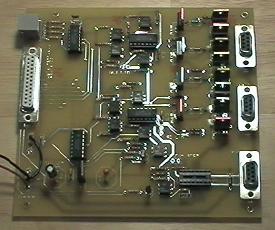
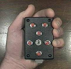
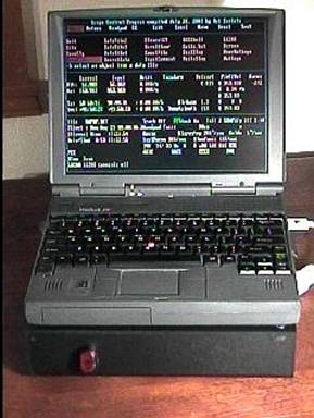
Table of Contents
Configuring the Stepper Software
Setting the altitude axis and azimuth axis
fullstep size in the config.dat file
Setting the slew (halfstep) speed
Setting the microstepping parameters
Coordinates' display on the screen
Your First Equatorial Initialization and Goto
Run
Your First Altazimuth Initialization and
Goto Run
German Equatorial Mount Meridian Flip
Updating the PEC data on the fly
Improve Local Finding/Tracking Accuracy
Improving the initializations - Optimizing
Goto and Tracking
Setting Backlash Values by Jerry Pinter
Interfacing with other programs
PCB Testing Prior to Motor + Computer
Hookup
PCB voltage diagnostic as reference to
ground
Hooking up the stepper windings, by Chuck
Shaw
Mechanical Aspects of the Drive
Making Your Own Drive Gears by Tom Krajci
ALT/AZ Conversion Lessons, by Chuck Shaw
UPDATE THE OTA (Optical Tube Assembly)
"SUB-SYSTEM":
UPDATE THE ROCKER BOX
"SUB-SYSTEM":
BUILD A NEW GROUND BOARD
"SUB-SYSTEM":
BUILD THE DRIVE ELECTRONICS
"SUB-SYSTEM":
UPGRADE THE DRIVE ELECTRONICS:
Design Details and Fabrication Notes:
1. OTA DESIGN AND FABRICATION:
Critical Path to find Balance Point:
Spin Alignment Technique…(Optical and
Mechanical Axis alignment)
2. ROCKERBOX DESIGN CONSIDERATIONS:
Azimuth and Altitude Trunions and Bearings
3. ELECTRICAL SYSTEM DESIGN CONSIDERATIONS:
Board Layout (additional FR circuitry)
Mounting location on Rockerbox
Cable harnesses/wire sizes/types
Power inputs (110vac vs 12vdc)
4. COMPUTER SUPPORT DESIGN CONSIDERATIONS
Laptop vs Microprocessor (Interactive vs
Black Box)
AltFullStepSizeArcsec (and
AzFullStepSizeArcSec)
Image Plane Derotation System by Chuck Shaw
You must exercise proper
safety precautions, including the wearing of glasses and thick rubber lug
shoes.
Shock hazard! Bodily injury
hazard! Any device using electricity is a shock and bodily injury hazard. You
must hook up the device properly and follow all safety precautions,
particularly when using electricity outdoors. If improperly hooked up or
improperly operated, electronic components can shock, overheat, melt, and
explode.
Peripheral equipment hazard!
Any device electrically attached to a computer can damage the computer if
hooked up improperly, or used improperly.
In particular:
- Never operate when the
equipment or cabling is wet or moist, even if there is only a possibility
that some of the equipment is wet or moist
- All grounding points
must be connected to the battery (-) terminal before turning on any
equipment; the grounds must never be disconnected while the unit is
powered on (disconnecting any ground will force the current to search out
a return path to ground, possibly by traveling through your body, causing
shock and bodily injury)
- Power leads must be
connected in proper order with the black ground wire connected before the
red positive voltage lead
- Power leads must not
be reversed: instant component failure is a certainty; components will
overheat and can explode with violent force
- Do not exceed 12 volts
DC power input: shorting more than 12 volts DC through your body can be
lethal.
- The power supply (+ or
positive voltage) lead can only be connected or switched on when the
software scope.exe is executing, and if running under Windows, can only be
connected or switched on if scope.exe is the foreground program
- Re-read the Safety Guide and Warning
- Attach the circuit board to the computer's parallel
port using a straight through 25 pin serial cable
- Attach the hand paddle to the circuit board
- Using a small 12 volt battery, or two 6 volt dry
cell batteries connected in series, attach the battery's (-) post to the
circuit board ground, which will be the black lead
- Turn on the computer
- Enter the appropriate parallel port in the
config.dat file: look near the end of the file for a line that starts
PportAddr, and enter the desired lpt #, usually a 1
- Run scope.exe, selecting either altazimuth or equatorial
alignment
- Attach the battery's positive (+) post to the
circuit board's red lead
- Check the hand paddle operation by pressing the
hand paddle buttons in turn, verifying that scope.exe is reading the
buttons properly
- Using the optional LED tester unit, plug it into
the altitude or the azimuth motor port (do not plug it into the field
de-rotator port), then turn on tracking in scope.exe, and verify that a.
the lights turn on and off in sequence from one side to the other, and b.
no more than 2 lights are on at any one time
- Verify motor movement by attaching a motor to the
azimuth/right ascension port of the circuit board (the middle db-9
connector), then turn on tracking in scope.exe
- Attach the other unipolar stepper motor to the
altitude/declination port of the circuit board and verify movement by
using the up button of the hand paddle
- If using a bipolar field rotator motor, attach it
to the field rotator port (the bottom db-9 connector, next to the raised
IC), then set the altitude to 80 degrees in scope.exe
Configuring
the Stepper Software
Scope.exe requires a
config.dat file. You can specify an alternative config.dat file by using
the command line option -c, ie, scope.exe -c \temp\config.tmp
Note: all variables, names, and strings are case
insensitive, so defaultbackground will work as will DefaultBackground
The following variables set
the display colors:
DefaultBackground
DefaultColor
TitleColor
BorderColor
MenuColor
DisplayColor
SelectColor
CurrentColor
SelectBackground
based on:
|
|
ConfirmQuit:
set to 1 if you wish a confirming message before the program quits
DisplayOpeningMsgs: if set to zero, opening and closing messages are suppressed
MoveHsMsgDeg:
how long of a slew allowed before a confirming message is displayed
F9Hotkey, F10Hotkey, F11Hotkey, F12Hotkey: optional user specified hotkeys; should only be set
via the program; delete from config file if you wish to erase them
InterfacePath:
location of controlling planetarium software program, ie, c:\guide\ also
location of Project Pluto's planetarium DOS program, dosguide.exe
UseMouseFlag:
if 1, use mouse to select menu items, datafiles, objects from datafiles, and
move the scope in microstep, halfstep, and auxiliary motions.
IACA_Flag:
if 1, use IACA to communicate with other IACA aware programs
GEMFlipPossible:
if 1 or on, GEM meridian flip can occur
AutoGEMFlip:
if 1, the GEM flip will occur automatically when the scope is asked to traverse
to the opposite hemisphere
AutoGEMFlipFuzzDeg: some value entered here, like 7.5 degrees, will give some fuzz or
wiggle room so that the scope doesn't flip back and forth from hemisphere to
hemisphere as you touch the centering buttons
Siderostat:
set to 0 if standard equatorial or altazimuth mount, set to 1 if you are using
a siderostat or uranostat flat to focus light into a stationary telescope tube;
you must set AzLowLimitDeg to about 90, AzHighLimitDeg to about 270, where due
south is about 180, the difference between the limits must be 180 deg or less.
This allows the altitude to exceed 90 deg, otherwise
the flat mirror will attempt to flip upside down when aimed at northly objects.
HomeAltDeg, HomeAzDeg: these are the home, or park coordinates
MsArcsecSec:
microstepping speed when the hand paddle is used to center objects, can be
changed while the program is running
AltFullStepSizeArcsec, AzFullStepSizeArcsec: these are the step sizes for the altitude and
azimuth steppers. The altitude is measured by using a precision level to set
the tube horizontal, resetting alt to 0, then moving the scope via the motors
until the precision level indicates the tube is exactly vertical. The ratio
between the displayed alt and 90 degrees is the amount to adjust the step size
by. Similarly, one complete turn in azimuth can be used to adjust the azimuth
step size
precessionNutationAberration: 1 if you wish precession, nutation, and annual
aberration corrections to be used with the equatorial coordinates, 0 if you
wish these corrections ignored
RefractFlag:
1 if you wish refraction to be used, 0 if you wish refraction to be display
only
UseAltAzECFlag:
if 1, ALTAZEC turned on at program startup.
UseAltAltECFlag:
if 1, ALTALTEC turned on at program startup.
UseAzAzECFlag:
if 1, AZAZEC turned on at program startup.
PointingModelFlag: if 1, PMC turned on at program startup.
HandPadPresentFlag: if 1 then handpad present, if 0, then handpad not present and handpad
is ignored. If the handpad is not connected or in an
error condition at program startup, it is ignored.
StartingHandPadMode: sets starting handpad mode, also ending handpad mode saved at program
exit to this variable: values are
|
|
HandpadDesign:
0 if standard handpad, 1 if using the four data lines to represent the four
directions (no mode control or speed control available: this is for autoguiders
that need simultaneous action in two directions, something not possible with
standard handpad design)
HandpadFlipUpDownWithGEMFlip: if 1 then handpad will flip its up/down direction
buttons when GEMFlip is on to match the declination direction reversal that
occurs when the GEMFlip has occurred
AltBacklashArcmin, AzBacklashArcmin: these are backlash values (if both are 0, backlash
is disabled). If backlash correction is desired, values should be positive. A
negative value means that the motor will move in the opposite direction than expected
in order to take up backlash
ABacklashSignalPPortPin17: if non-zero, then parallel port pin 17 used to
signal the direction of the 'A' motor backlash: logical high if backlash
direction is CCW, logical low if backlash direction is CW (can be used to
control motorized counterweights); starting value is logical low
AltLowLimitDeg, AltHighLimitDeg, AzLowLimitDeg,
AzHighLimitDeg: these limits are
active only when HsTimerFlag is set to 1 (on); if HsTimerFlag is on and
desiring to disable the alt limits, set both alt limits to 0; if HsTimerFlag is
on and desiring to disable the az limits, set both az limits to 0
GuideArcsecSec:
guiding correction speed, can be changed while the program is running
The following are drift rates
that a star will be dragged across an autoguider with knife-edge
detector. These autoguiders work by expecting the tracking rate to be
slightly off guaranteeing that the star will always eventually move across the
knife-edge. When the star crosses the knife-edge the autoguider gives it
a little kick in the opposite direction, then waits
for the star to reappear.
|
GuideDragAltArcsecPerMin GuideDragAzArcsecPerMin |
GuideDragRaArcsecPerMin GuideDragDecArcsecPerMin |
HPUpdateDriftFlag: if 1, then the drift is updated at the end of a handpaddle guiding
session. Drift is calculated based on accumulated guiding corrections
over the session and then automatically adopted.
DriftAltArcsecPerMin: starting value of altitude drift in arcseconds of angular movement
per minute of time.
DriftAzArcsecPerMin: starting value of azimuth drift in arcseconds of angular movement per
minute of time.
DriftRaDegPerHr:
starting value of declination drift in degrees of angular movement per hour of
time.
DriftDecDegPerHr: starting value of right ascension drift in degrees of angular
movement per hour of time.
PECFlag: if
1, then PEC turned on at program startup time.
AutoAltPECPin:
parallel port pin(s) that auto synchronization of altitude will be read from:
must be 15, 16 or 17, or 10+12+13 (3 pin combination), or deleted from
config.dat (default will be 17 then). If you use the 10+12+13, be careful
not to simulate it by any of the following hand paddle key presses: UpKey +
DownKey + CCWKey, or CCWKey + CWKey, or UpKey + RightKey, or DownKey + LeftKey
AutoAltPECSyncOnFlag: turns on automatic synchronization of the altitude PEC using the
AutoAltPECPin pin of the parallel port
AutoAltPECSyncLowHighFlag: if 0, synch point occurs after +5 VDC has been
applied, and at the moment ground is applied; if 1, synch point occurs when
+5VDC is applied after pin has been grounded.
AutoAltPECSyncDirFlag: direction that alt PEC must be moving in order to
trigger auto-sync: 0 = either direction, 1 = CCW direction, 2 = CW direction
AutoAltPECDeBounce: if 1 or on, then software will debounce the synchronizing signal: the
debounce period ends when the PEC index is between the ¼ and ¾
point of the PEC cycle
AutoAzPECPin:
parallel port pin that auto synchronization of azimuth will be read from: must
be 15, 16 or 17, or 10+12+13 (3 pin combination), or deleted from config.dat
(default will be 15 then). If you use the 10+12+13, be careful not to
simulate it by any of the following hand paddle key presses: UpKey + DownKey +
CCWKey, or CCWKey + CWKey, or UpKey + RightKey, or DownKey + LeftKey
AutoAzPECSyncOnFlag: turns on automatic synchronization of the azimuth PEC using pin 15 of
the parallel port
AutoAzPECSyncLowHighFlag: if 0, synch point occurs when ground is removed from
pin; if 1, synch point occurs when ground is applied.
AutoAzPECSyncDirFlag: direction that az PEC must be moving in
order to trigger auto-sync: 0 = either direction, 1 = CCW direction, 2 = CW
direction
AutoAzPECDeBounce: if 1 or on, then software will debounce the synchronizing signal: the
debounce period ends when the PEC index is between the ¼ and ¾
point of the PEC cycle
FullstepsPerPECArray: This allows periodic correction for single through quad worms by
tying the PEC sequence to an amount of fullsteps, not to a motor's single turn.
Positive values in PEC.DAT indicate too much clockwise motion. Values are in
tenths of an arc second. A total of 200 values per PEC are used regardless of
number of fullsteps per PEC array. PEC must be synchronized by placing the
motor shafts in the predetermined starting position and hitting the 'PEC on'
keyboard menu item selection or by using the auto-sync option.
PECIxOffset.A, PECIxOffset.Z: index offsets of both axes between rotor position of
0 and synch point, for instance, if the current position coordinate is zero
with the rotor in the up position, and you have 200 fullsteps for a PEC cycle,
and if the PEC synch point occurs with the rotor in the down position, then the
offset will be 100; leave at 0 until PEC is turned on and synchronized, at
which point let the program determine these values
FRStepSizeArcsec: field rotation motor step size, set to 0 if you wish field rotation
disabled
SectoredFRDrive:
if using a sectored field de-rotation drive, set to 1, otherwise field
de-rotator motor may slew large angles after the scope finishes a slew.
FRStepSpeedMilliSec: speed of field rotation motor when slewed by hand paddle
ReverseFRMotor:
reverse field rotation motor direction
FocusMethod:
can be 0, 1, 2, or 3:
- Connecting parallel port pins 16 and 17 to a pair
of relays to control a small DC motor for focusing. Pin 16 focuses
'out' and pin 17 focuses 'in'. This can be operated with the field
rotator concurrently.
- As above in option 0, with the addition of
parallel port pins 1 and 14 for slow speed control. Field rotation
is disabled with this option.
- Using the field rotation motor control circuit
with a small stepper motor for focusing. This uses parallel port
pins 1 and 14 for pulse and direction.
- 3. Adding a second MC3479 bipolar stepper control
circuit with a small stepper motor for focusing. This
uses parallel port pins 16 and 17 for pulse and direction. Both the
field rotation and focus motors can be operated simultaneously.
Along with the altitude/declination and azimuth/hour angle motors, this
means that four motors are controlled at the same time.
ReverseFocusMotor: if 1, then reverse direction of focusing motor
FocusFastStepsSec: if using bipolar stepper motor for focusing, then this value contains
the fast speed setting in steps per second
FocusSlowStepsSec: if using bipolar stepper motor for focusing, then this value contains
the slow speed setting in steps per second
FocusPosition:
if using bipolar stepper motor for focusing, then this value contains the
focuser position in steps
MotorControlMethod:
- 0 = pulse width modulation of unipolar stepper
motors (if in doubt, pick this option),
- 2 = pulse and direction control, if option 2, set
the fullstep size to the amount moved every motor pulse
KeepAlivePPortPin: set to the parallel port pin (1, 14, 16, or 17) you wish to use for
input to a keep alive circuit; the pin will pulse at least 9 times per second;
design the circuit so that the power supply to the motors is cut off if the pin
fails to trigger after a short period of time.
MotorWindings:
4 or 5: number of windings that the stepper motors have;
almost all have 4 windings, but the software can work with 5 phase motors such
as those from Vexta
if going with 5 phase motors then please observe the
following notes:
An option is provided for
driving 5-phase motors by using pins 16 and 17 for the fifth phases of the
A and Z motors respectively. To use this option, set MotorWindings to 5 in
CONFIG.DATA. Note that the choice of 4 or 5 phases for has no effect
on the parallel port outputs for the field rotation motor.
The following changes in
design or usage apply in the 5-phase case:
- Driver circuitry must use H-bridge design.
Refer to "Jones on Stepping Motors" at
http://www.cs.uiowa.edu/~jones/step/ or design data for the SGS
Thompson L298 Dual Full Bridge Driver at http://www.st.com/stonline/books/pdf/docs/1773.pdf
- Interpretation of the 0's in
the microstepping table above and in variables such as HsOut changes
from "off" to "grounded" (see Jones).
InvertOutput:
Original designed called for 7404 inverters to drive the transistors, hence
InvertOutput 1 in the original config.dat (parallel port output goes high, hex
inverters go low, and drive transistors turn off, hence the need to invert the
output). In the original design, if opto-isolators were used, then
InvertOutput 0 (parallel port output goes high, hex inverters go low,
opto-isolators turn on pulling output low, hex inverters go high, and drive
transistors turn on, hence no need to invert output). If using the printed
circuit board, the pcb design uses 7408 and gates (parallel port output goes
high, 7408 and gates go high, opto-isolators turn off allowing output to return
to high, 7408 and gates go high, and drive transistors turn on, hence no need to
invert the output). Screw this up and you will pump a lot of current
through the steppers!
ReverseAMotor:
set to 1 if you wish to reverse direction of the 'A' motor (the altitude or
declination motor). This is equivalent to swapping winding leads 1 and 3.
ReverseZMotor:
set to 1 if you wish to reverse direction of the 'Z' motor (the azimuth or
right ascension motor). This is equivalent to swapping winding leads 1
and 3.
HsRampStyle:
set to 0 if you wish the old simple ramp, and set to 1 if you wish the new 'S'
shaped ramp curve, where the ramp starts slowly, speeds through the middle
range, and slows down for the highest speeds at the end of the ramp.
HsTimerFlag:
set to 1 if you wish to use IRQ 8 to time the halfstep slews, this allows for
realtime updating of scope coordinates, keyboard interruption of slews, and
altitude limit checking during a slew, otherwise if set to 0, halfsteps are
timed by a delay loop with interrupts disabled to avoid interruption; using
IRQ8 works perfectly in DOS, not at all in Win 3.x, and slowly in Win95
MaxDelay, MinDelay, HsDelayX: these set the slowest and fastest slew speeds:
when using IRQ 8 timing of
halfsteps, ramp speed starts at MaxDelay and achieves highest speed at
MinDelay; with interrupt 8 method of timing the halfsteps, speed can be
converted to halfsteps per second by dividing MaxDelay and MinDelay into
1,000,000, so that a MaxDelay value of 1000 means 1000 halfsteps per second,
and a MinDelay value of 200 means 5000 halfsteps per second.
when using delay loop timing
of halfsteps with interrupts disabled, ramp speed starts at (MaxDelay - MinDelay)* HsDelayX and
achieves highest speed of MinDelay *
HsDelayX, where HsDelayX is used as a multiplier to keep the MaxDelay and
MinDelay values reasonably sized on fast CPUs.
HsRampX: the
amount of time to ramp up or ramp down is multiplied by HsRampX
InterruptHs:
number of halfsteps before interrupts disabled if using delay loop timing of
halfsteps
HoldReps:
time to lock stepper rotors at beginning and end of slew to prevent shaft
oscillation and overshoot
HsOverVoltageControl: for optional halfstep high speed slewing over-voltage control; if
desired, enter a non-zero value. Control line is parallel port pin
#17. Value entered here will be the Delay value at which the over-voltage
control line will be toggled logical high. Pick a value between MaxDelay
(slowest speed or greatest delay) and MinDelay (fastest speed or least delay
between halfsteps)
MaxConsecutiveSlews: maximum number of consecutive slew attempts to reach a desired
position. If slews cannot reach position, scope begins tracking.
This prevents oscillations when MsRepsTick or PWM values are low and tracking
speed exceeds maximum microstepping speed.
MsPowerDownSec:
number of seconds before idle motor will power down during microstepping.
PWMRepsTick:
count of pulse width modulations per bios clock tick. Set to average value of
PWMReps displayed on screen.
AvgPWMRepsTickOnFlag: if 1, then auto-averaging of the PWMRepsTick will occur, based on the
actual number of PWM repetitions per timer tick as averaged over 3.5 seconds;
if 0, then the PWMRepsTick value as entered in the config.dat file will be
used.
MsDelayX:
repetition value of each value in the microstepping arrays, this allows for
smaller arrays when needing large PWM[] values for
fast PCs.
MsPause: the
number of dummy loop repetitions at the end of every PWM[]
loop. This allows for fine low voltage resolution when using a high voltage
power supply
Ms: number
of microsteps: up to 40 per each fullstep
MaxIncrMsPerPWM:
maximum microstep increment per pulse width modulation. In order to
microstep faster, microsteps can be skipped. Consequently, this sets the
maximum microstepping speed. Microsteps can be skipped up to very roughly
4 per fullstep. For instance, if you have 20 microsteps per fullstep,
then you can enter a value of 5 here. Consequently, this variable also
controls the maximum microstepping or tracking speed. For instance, if
you set it to 1, then your max microstepping speed will be the PWMRepsTick * 18 (ticks per
second). The max value that you can set it to will be the number of
microsteps in a halfstep, because the fastest the microstepping routine can
work at is one halfstep per PWM. (if the number
exceeds MsHsToggleIncrMsPerPWM, the routine switches from microstepping per
each PWM to halfstepping per each PWM)
MsHsToggleIncrMsPerPWM: while microstepping, the routine will switch into
halfstep mode if necessary. This is toggled when the number of microsteps
per each PWM repetition exceeds MsHsToggleIncrMsPerPWM. For instance, if the PMW repetitions per timer tick is 50, and if
MsHsToggleIncrMsPerPWM is 5, and you ask the program to track at more than
250 (50*5) microsteps per PWM, then the routine will toggle to halfstep
movement. Max speed is still the # of microsteps per fullstep
divided by 2, equivalent to halfstepping. In this example of 20
microsteps per fullstep, the max speed is 20/2 or 10 microsteps per PWM, or 500
(50*10) microsteps per PWM. Overall speed in any case is still limited by
MaxIncrMsPerPWM.
MaxPWM:
maximum pulse width modulations, and consequently the maximum value that any PWM[] value can take. This can be set higher than PWM[0] so that PWM[1]... can be set higher than PWM[0] to
ameliorate stepper motor cogging
PWM[0] through PWM[19] : These values sets the voltages for individual
microsteps. In general, these values should reflect the ratios discussed
earlier. If the microstepping is not smooth, adjust these values. If the motors
become too warm and take too much current, increase MaxPWM, lower the PWM[0] through PWM[19] values, decrease MsDelayX and/or
increase MsPause. When tracking, the steppers should draw no more than
approximately 0.1 amp while still producing adequate
torque.
The rotor is positioned based
on the inverse square strength of two adjoining windings, for instance,
PWM[0] 100 : 0
means that the first
microstep has a current value for winding A of 100 and a current value for
winding B of 0 positioning the rotor exactly over winding A, and,
PWM[10] 100 : 100
means that the 11th microstep
has a current value for winding A of 100 and a current value for winding B of
100 positioning the rotor exactly between winding A and winding B, and,
PWM[19] 29 : 100
means that the 20th microstep
has a current value for winding A of 29 and a current value for winding B of
100 positioning the rotor 9/10ths of the way between winding A and winding B
(there is a slight deadband where a certain amount of counts, usually about 10,
are needed for the motor to feel the current pulse at all);
here are the values for 20 microsteps:
|
PWM[0]
100 : 0 PWM[1]
100 : 29 PWM[2]
100 : 45 PWM[3]
100 : 56 PWM[4]
100 : 65 PWM[5]
100 : 72 PWM[6]
100 : 81 PWM[7]
100 : 88 PWM[8]
100 : 95 PWM[9]
100 : 98 |
PWM[10]
100 : 100 PWM[11]
98 : 100 PWM[12]
95 : 100 PWM[13]
88 : 100 PWM[14]
81 : 100 PWM[15]
72 : 100 PWM[16]
65 : 100 PWM[17]
56 : 100 PWM[18]
45 : 100 PWM[19]
29 : 100 |
Optional variables: QSC_..., which stands for
QuarterStepCorrection: the '_a' through '_d' indicate the winding, and the
extra '2' indicates the intermediate halfstep; enter corrective values in
fullsteps, for instance, if the motor moves too far for the 'a' winding by 0.1
fullstep halfway through its range, and no other corrective actions are
required, here is what the entries will look like for the 'a' winding (for
windings 'b' through 'd', duplicate these entries, replacing the 'a' with the
winding letter 'b', 'c', or 'd'):
QSC_a0
0 : 0
QSC_a1
0 : 0
QSC_a2
0.1 : 0
QSC_a3
0 : 0
Optional variables: PWM_... which taken together allow
compensation for current variation to each stepper motor winding. It has
been discovered that the 8 output lines from the circuit may vary in output
current thanks to variations in the parts themselves. In addition, there
may be variations in motors. Some of the quarter step correction (QSC)
issues may be due to variations in motor winding current. By allowing for
individual current adjustment of each output line, one can tune very output
line to give the same current. For instance, if one finds that the 2nd
output line ('B' winding of the altitude/declination motor) reads a low current
compared to the other output lines, the other lines can have their output
current lowered by the software to compensate. Default is no compensation
and config.dat does not need to be changed. If you wish to use output
line/motor winding current compensation, add the following variables to
config.dat. A value of 1 means output 100% of available current, a value of 0.5 means output 50% of available
current, and so forth.
Here is what the entires will
appear to handle a compensation for a disparate 'B' winding of the
altitude/declination motor:
PWM_A_a_Comp 0.8
PWM_A_b_Comp 1
PWM_A_c_Comp 0.8
PWM_A_d_Comp 0.8
PWM_Z_a_Comp 0.8
PWM_Z_b_Comp 0.8
PWM_Z_c_Comp 0.8
PWM_Z_d_Comp 0.8
PPortAddr:
parallel port address: enter a 1 or 2 or 3 for lpt port 1 through 3, or enter
the base address in a 3 digit decimal form where portid lpt1 = decimal 888 (hex
378) lpt2 = decimal 632 (hex 278), monochrome video card = decimal 956 (hex
3BC)
COM3Base:
com3 base address in decimal form (if entry not listed in the config file, will
default to 0x3E8 in hex or 1000 decimal)
COM3IRQ:
com3 interrupt from 3 to 15 ( if entry not listed in
the config file, will default to 4)
COM4Base:
com4 base address in decimal form (if entry not listed in the config file, will
default to 0x2E8 or 744 decimal)
COM4IRQ:
com4 interrupt from 3 to 15 (if entry not listed in the config file, will
default to 3)
EncoderString:
options are:
- NoEncoders,
- BSeg = Bob Segrest unit,
- ResetViaR = MicroGuiderIII, Ouranos, StarPort,
and types that support reset by 'R...',
- ResetViaZ = BBox, NGC types, and types that
support reset by 'Z...',
- NoReset = SkyWizard and types that are not
resettable,
- Ek = encoder box as designed by Dave Ek,
- Mouse = using encoders from mouse (turn off
acceleration, etc in mouse driver)
- LM629Serial = use serial interface to LM629 servo
controller
EncoderComPort:
enter 1 or 2 for com1 or com2, ignored if using Mouse driver
EncoderBaudRate:
baud rate to access the encoder interface box; normally 9600
SerialWriteDelayMs: millisecond wait after querying encoders before reading encoders;
some wait is required, often 20-50 milliseconds
AltEncoderCountsPerRev, AzEncoderCountsPerRev: encoder counts per full revolution of the telescope
mount; max of 65,534 with some encoder boxes having lower limits; if unable to
set limits, then start scope.exe in serial test mode, turn on encoder box,
enter commands from encoder box manual to manually set the resolution, check
manual for any confirmation commands, if successful, write down what you
entered and what the encoder box returned and send to the author, exit
scope.exe, restart scope.exe in normal mode - do not turn off encoder box - and
continue with normal operation of the telescope
AltEncoderDir, AzEncoderDir: allows changing of direction that encoder counts up,
set to 0 to reverse count direction
EncoderErrorThresholdDeg: if encoder readings compared to current coordinates
exceed this threshold, then current coordinates reset to encoder readings; if
0, coordinates not reset no matter how great the discrepancy
TrackEncoderErrorThresholdDeg: as above, but the error threshold to be used when
tracking or slewing is on
MakeEncoderResetLogFile: set to 1 if you wish encoder threshold violations to
be recorded into the file "Encoders.txt"
EncoderOffset.A, EncoderOffset.Z: offsets of encoder position from scope position in
radians; let the software calculate these values
LX200ComPort:
enter 1 or 2 for the com port to receive LX200 styled commands from external
PC; set to 0 if not used
LX200BaudRate:
baud rate for LX200 control; normally 9600, but if possible to change the
external controlling program, set the baud rate to highest speed for faster
data throughput and consequent less impact on motor movement
LX200MotionTimeoutSec: if no LX200 stop motion command received, motion
will stop in this many seconds
LX200SlewHs:
if no slew stop received, slew distance in halfsteps
LX200_LongFormat: start the program in emulate long format mode
Current.Alt, Current.Az: current telescope altazimuth coordinates in degrees
AccumMs.A, AccumMs.Z: current telescope altazimuth coordinates in accumulated microsteps;
these are used for the telescope's starting and ending position.
Calculate the current altazimuth coordinates in degrees by multiplying the
accumulated microsteps * the microstep size (which is fullstep size divided by
number of microsteps).
StartInitState:
This controls the startup state of the initializations. It operates
exactly as the query at program startup:
- 0 means ask user per traditional menu options,
- 1 means adopt equatorial alignment,
- 2 means adopt altazimuth alignment,
- 3 means adopt no alignment at all, and
- 4 means to reuse last alignment.
- Any other option than 0 means that you will not
be queried. This is a config.dat replacement for the query menu at
startup time. Use it if your answer to the opening query is always
the same. Default is 0, to query the user.
OneInit, TwoInit, ThreeInit: the stored initializations used to orient the
telescope to the sky; these are written by the program; each line consists of
Ra, Dec, altitude, azimuth, and sidereal time all in degrees
Z1Deg:
elevation offset to horizon perpendicular
Z2Deg:
optical axis error in same plane
Z3Deg:
correction to zero setting of elevation (this can be set to zero permanently
and the altitude offset function in the program used to make an automatic Z3
correction)
LatitudeDeg:
used only for rough initial altaz alignment
CMOS_RTC_Access:
CMOS Real Time Clock access: 0 = direct port access, 1 = bios call access - use
1 only if machine locks up including during ATimes test (very rare - only one
reported instance)
LongitudeDeg:
your site's longitude, used to determine HAOffset and local sidereal time
Tz: used to
determine sidereal time, the initialization process does not depend on sidereal
time or longitude, instead relying completely on the time interval between
initializations
DST: also
used to determine sidereal time
TestString:
- NoTest = normal program execution,
- PreloadGuidexx.dat = preloads the program with
guidealt.dat and guideaz.dat, then runs normally,
- Track = start 2 motor tracking with default value
Setting the
altitude axis and azimuth axis fullstep size in the config.dat file
Use the move/halfstep menu
option to move the telescope a set amount of halfsteps. Assuming fullstep
size of 3 arcseconds, and ability to measure angle change down to several
arcminutes (8192 count per revolution encoders, or precision bubble), then
execute at least 5,000 steps for 1% accuracy. If encoders are used, the
program will automatically display the fullstep values for AltFullStepSizeArcsec
and AzFullStepSizeArcsec that you should enter into the config.dat file.
Try for 0.1% or 1 part in 1000 accuracy (move at least 50,000 steps, or roughly
45 degrees).
Setting the
slew (halfstep) speed
Because computer capabilities
vary greatly and because of widely varying motor and scope mounts, it will be
necessary to spend time optimizing the values relating to halfstepping in the
configuration file, config.dat. I use a 486/100 laptop. Included is config.386,
which were the values I used on my old 386/20 with 387
math coprocessor.
To set the halfstep slewing,
try to set HsTimerFlag to 1, enabling the interrupt drive timing. The interrupt
driven timing is independent of cpu speed, so
regardless of the computer's speed, set MaxDelay to 2000, MinDelay to 500, and
HsRampX to 5. MinDelay and MaxDelay can be converted to Hertz by dividing them
into 1,000,000. For instance, if MaxDelay is 1000, then Hertz is 1000 or step
frequency is 1000 steps per second.
Be sure to run scope.exe
after booting to DOS, or exiting Win95 to DOS. The motor's starting speed is
set by MaxDelay, the fastest speed by MinDelay, and the time to ramp up and
down set by HsRampX. Adjust to suit your combination of steppers, drive
voltage, and scope's torque loading.
If the interrupt drive timing
won't work and it is necessary to use the delay method of timing the halfsteps,
set HsTimerFlag to 0. If you have a cpu close to a
386/20, start with MaxDelay 8000, MinDelay 3000, and HsDelayX 1. If you have a cpu close to a 486/100, change HsDelayX to 2. Speed starts
at (MaxDelay-MinDelay)*HsDelayX, and achieves fastest speed at
MinDelay*HsDelayX. HsDelayX is used as a multiplier to keep the MaxDelay and
MinDelay values reasonable; otherwise the array size becomes too large. Again,
adjust as necessary to fit the motors, the drive voltage, and the scope.
Setting the
microstepping parameters
To set the microstepping:
start with the suggested PWM[] values ranging from 100
on down. Start with MsDelayX = 1, and MsPause = 0 if on a slower machine, and
MsDelayX = 6 if on a faster machine. Adjust MsDelayX such that PWMRepsTick
displayed (turn on tracking for a few seconds) is 20 to 40. People have
reported mixed success with slow machines and PWMRepsTick values as low as 7. Values as high as 50 to 100 will also work. Find the
MsDelayX value that results in smoothest motor rotation, adjusting MsPause to
higher values possibly to 500 or more, to reduce voltage and current draw, and
to smooth the motor rotation.
Here's how the microstepping
is laid out:
To reverse motor direction,
swap motor leads #1 and #3, or alternatively, #2 and #4. Finally, you can
swap motor directions in the config.dat file.
Adjusting the microsteps:
The program handles
microstepping up to 40 microsteps per fullstep.
For 10 microsteps per
fullstep, the windings are combined as follows:
; starting a line with ‘;’ means a comment line
|
;rotor centered on winding PWM[0]
100 PWM[1]
100 PWM[2]
100 PWM[3]
100 PWM[4]
100 |
;rotor between windings PWM[5]
100 PWM[6]
85 PWM[7]
70 PWM[8]
55 PWM[9]
35 |
For 20 microsteps per
fullstep, the windings are combined as follows:
|
;rotor centered on winding PWM[0]
100 PWM[1]
100 PWM[2]
100 PWM[3]
100 PWM[4]
100 PWM[5]
100 PWM[6]
100 PWM[7]
100 PWM[8]
100 PWM[9]
100 |
;rotor between windings PWM[10]
100 PWM[11]
94 PWM[12]
86 PWM[13]
77 PWM[14]
69 PWM[15]
62 PWM[16]
54 PWM[17]
46 PWM[18]
37 PWM[19]
27 |
(this
written with 10 microsteps per fullstep in mind)
Set TestString to Track in
the config.dat file, and choose 1 microstep per second. Put a piece of masking
tape on the motor shaft and watch it carefully for even spacing of the
microsteps. If the step is too far apart, bring the voltages closer together.
For instance, if the spacing between microstep #0 and #1 is too far, then lower
PWM[9], if the motor hardly seems to move between #0
and #1, increase PWM[9]. Again, if the spacing between #3 and #4 is too large,
then increase #3, or decrease #4, or a combination of the two. You can
change the PWM[] values on the fly. When you get
them the way you wish, copy the values to the config.dat file.
Here is a contributed method:
"There is a way that I used to find the proper PWM numbers for the drive
that can interest you:
I started first with
approximate numbers in the software.
I mounted a 7.96"
plastic rod on the shaft to get a 50" circumference or
0.025" per microstep.
I put the software in
TestString = Track mode with 0.1 step per second.
I measure each microstep
position with a micrometer head for 4 full steps.
I calculate the mean
displacement for each microstep 0 to 1, 1 to 2 etc..
And more important I PUT THE
CALCULATED DATA ON A GRAPHIC SHEET.
This gives me a nice smooth
curve. I pickup the PWM numbers for 0.025", 0.050", 0.075" and
so on. I put back these numbers in the config.dat file and restart the
measurement and write down. The result was almost perfect. I had to change the
numbers of only plus or minus 1."
Yet another suggestion from
Juan Herrero: "I was going nuts trying to measure and adjust the variances
between the microsteps in my Altaz controlled motors. I had 4 drinking straws
taped end on end. Attached to the stepper motor shaft.
The end of the 3' straw contraption, would only move a
couple of millimeters per microstep. It was very difficult to take the
measurements. And then...Mel decided to improve his software from 10 to 20
microsteps! How could I measure all those tiny steps ?
Well yesterday I saw the light! Laser light that is. I went to RadioShack and
got their cheapest laser pen pointer. Taped it to the motor
shaft. And projected the beam on the wall.
I can now measure microstep movements 20mm big! TA DA!"
Date:________
Computer _________ Dir:_________ Scope.exe
Compiled:__________
Telescope _____PCB ______
InvertOutput
0 0 for PCB
FR Step Size
2.25 for ½ step, 4.5 for full step
HSTimerFlag
1 for IRQ8 (DOS), 0 for Windows
Max
Delay
2000 (DOS)
Min
Delay
1000 (DOS)
HsDelayX
N/A DOS, Multiplier for Windows slews
PWMRepsTick
Shoot for 20-60
MsDelayX
SlowPC=1, fast PC=6
MsPause
Current Control during MS
Motor Current
PWM[0]
a 100 Step0 = PWM[0]
PWM[1] b
100 Step1=PWM[1]+PWM[9]
PWM[2] c
100 Step2=PWM[2]+PWM[8]
PWM[3] d
100 Step3=PWM[3]+PWM[7]
PWM[4] e
100 Step4=PWM[4]+PWM[6]
PWM[5] f
100 Step5=PWM[5]+PWM[5]
PWM[6] g
Step6=PWM[6]+PWM[4]
PWM[7] h
Step7=PWM[7]+PWM[3]
PWM[8] i
Step8=PWM[8]+PWM[2]
PWM[9]
j
Step9=PWM[9]+PWM[1]
SETUP: Pointer
and scale on Motor, 10amp Range on Meter.
Calculate current to meet
wattage limit on Motor: V=IR, VRated * IRated = WattsRated,
Iops = WattsRated / Vops __________________________
1. Start: Default
PWM's, MsDelayX=1 for slow and up to 6 for fast,
MsPause=0,
PWMRepsTick=display in Track
2. Adjust MsDelayX till
PWMRepsTick = 20 <-> 60 (may increase current) and motion is smooth. (Motion is smoother at lower PWM's, but current
is higher and so is sound)
3. Adjust MsPause to get
current within Motor Wattage Limits: (When current is too low, motion gets
jerky)
Increase MsPause, Decrease
PWM[x]'s or Decrease MsDelayX to Decrease
current
Decrease MsPause, Increase PWM[x]'s, or
Increase MsDelayX to Increase current
4. Adjust PWM[x] Matrix for
even steps (Larger PWM[x]'s decrease PWMRepsTick
If spacing is too big:
bring voltages closer together;
if spacing too small, increase the difference in
voltages:
If the move between 0
and 1 is too big,
reduce [9] to decrease how much winding B pulls off of
centered on A
If motor barely moves
between 0 and 1,
Increase [9] so winding B pulls it more off of centered on A
If spacing between [3]
and [4] is too big,
increase [3] or decrease [4] (or both)
PWM (winding
A) Step
#
PWM (winding B)
100 a
0--0--------------------0 a 100
100 b
1---1-------------------9 j ___
100 c
2-----2-----------------8 I ___
100 d
3-------3---------------7 h ___
100 e
4---------4-------------6 g ___
100 f
5-----------5-----------5 f 100
___ g
6-------------6---------4 e 100
___ h
7---------------7-------3 d 100
___ i
8-----------------8-----2 c 100
___ j
9-------------------9---1 b 100
5. Iterate 2-4 till current
within wattage limit,
PWMRepsTick = 30-60, and motion is smooth/even
6. Adjust MinDelay and
MaxDelay (and HsDelayX if Windows)
to allow smooth and fast slews with no buzzes (Min
Delay = Buzz)
7. Copy these values into
Config.dat
Bob Norgard has written
a webpage on adjusting the microstep values. It is at http://home.gci.net/~rnorgard/Scope/Microsteps
Tom Krajci has an Excel
spreadsheet to adjust the microstepping available at http://www.egroups.com/Logon
and look at the scope-drive archives.
Andrew Martyn has an
excellent microstep and QSC configuration page at www.spin.net.au/~afmartyn/index.html
+---------
Scope Control Program compiled
¦File Motors
Handpad EC Init
Coord Move Reset
¦
+------------------------------------------------------------------------------¦
¦Quit SaveCfg DataFile DataFile2 DataFile3 ¦
¦DataFile4 ClosestGT ScrollTour InputComment DOSShell ¦
¦Guide.bat Hotkeys ReadSlew WriteSlew LX200 ¦
¦TestSerial Screen
¦
+------------------------------------------------------------------------------¦
¦->
quit the program
¦
¦ Current Input
Drift Encoders Refract
FieldRot Focus ¦
¦Alt: 30.028
30.028 0.000/m 0 A 315.562 ¦
¦Az: 200.000
200.000 0.000/m R 0.31 /m ¦
¦
M 315.56 ¦
¦Ra:
¦Dec:
-13:44:45 -
+------------------------------------------------------------------------------¦
¦File Track Off FRTrack Off Init 2 GEMFlip Off ¦
¦Object Handpad
Off DUon
m ¦
¦Sidereal
Time 16:45:21 Mouse Microstep 300"/sec Guide
5"/sec ¦
¦Date/Time
12/27 10:
¦ PWM / 37 Ms 0
0 b00 c00 000 QSC ¦
¦PEC AZEC AAEC ZZEC PMC
¦
¦Slew Done
¦
¦LX200
LX200 commands off
¦
+------------------------------------------------------------------------------+
Use the cursor keys to select
a menu item. Left-Right cursor keys select the main menu category and
Up-Down cursor keys select the submenu item. Just under the menu selections,
a more detailed description of the menu item's action is displayed.
The "Current"
coordinates display where the telescope is currently pointing.
The "Input"
coordinates display user input coordinates, ready for the telescope to be moved
to, if "Move To/Equat" or "Move To/Altaz" is selected from
the menu.
The "Drift"
coordinates show the current drift rate in each axis.
Encoder coordinates are
displayed in degrees and in raw counts.
The "FieldRot" or
field rotation shows one value if field rotation motor disabled, otherwise
shows four values. The upper value is the current field rotation
angle. The second value down is the rate of field rotation in degrees per
minute. The next value down is the angle of the field rotation motor.
The two numbers immediately below show the accumulated step count (clockwise
adds, and counterclockwise subtracts), and the number of resets: all modulus
100. The final angle displayed under this line is the guide buttons rotation
angle.
The "Focus"
position shows the accumulated count of the focuser stepper. If no number
is displayed, then the FocusMethod is set to something other than stepper motor
control
The "AirMass" field
shows the airmass number, or number of atmospheres
that the telescope is aimed through.
The "DomeAzimuth"
field shows the angle of the dome rotation in degrees.
The "File" area
indicates which data file, or external program or device, has sent coordinates
to the program.
If the coordinates have been
reset because the encoder reset threshold values in the config.dat file have
been exceeded, the "File" field will display a message stating the
scope motion immediately preceeding the reset (enc.res.slew = encoder reset
after slew, enc.res.on = encoder reset after tracking on, enc.res.off = encoder
reset after tracking off), and a running count of the encoder resets for that
particular scope motion.
The "Track" field
shows if tracking is on or off.
The "TrackFRMotor"
shows if the field rotation motor tracking is enabled/disabled.
The "Init" field
shows how many initializations have been done so far.
The "GEMFlip"
indicates if a german equatorial mount has been flipped across the meridian.
The "Object" area
shows which object from the data file has been loaded into the input
coordinates.
The "Handpad" field
shows what handpad mode the program is currently in, and if that mode is active
(for instance, if the mode is set to focus, and control of the focus motor is
activated by the mode switch, then an 'on' will appear), if handpaddle auto-drift-update
is on or off (DUon or DUoff), if guiding corrections saved to a file are
finished then a "Fn" will appear, and further to the right, which
buttons are being pressed and the switches' positions. C=clockwise button
pushed, W=counterclockwise button pushed, U=up button pushed, D=down button
pushed, m=speed switch in microstep position,H=speed
switch in halfstep position, L=mode switch in left position, R=mode switch in
right position, x = up, down buttons reversed.
The "Mouse" field
shows the mouse mode: mouse modes include menu, where the traditional point and
click is available, and various move modes, where mouse movement moves the
telescope.
The "Microstep"
field displays the current microstepping speed in arcseconds per second.
The "PWM" field
shows the actual number of pulse width modulations per bios clock tick (there
are about 18.2 clock ticks per second), and the averaged number of PWMs per
timer tick that the program is currently using.
The "Ms" area shows
the number of microsteps moved per timer tick (occurs 18.2 times per second)
for altitude and azimuth motors, the winding from 'a' to 'd',
the microstep within the winding for altitude and azimuth motors.
The "QSC" shows the
current quarter step correction values for both motors.
The "Guide" field
displays the current guiding speed in arcseconds per second.
The "FastFocus"
displays the fast focus speed in steps per second.
The next area shows if the
field rotation motor is moving "Fr+" or "Fr-", any
auxiliary control lines activiated "A1" or "A14" or
"A16" or "A17" and if the focus motor is moving
"Ff+" (fast out) or "Ff-" (fast in) or "Fs+"
(slow out) or "Fs-" (slow in).
The "SlowFocus"
displays the slow focus speed in steps per second.
The "PEC" area, if
PEC is on, shows the altitude and azimuth indexes and correction values in
tenths of an arcsecond, respectively. In addition, if the auto-sync of
altitude PEC or azimuth PEC is enabled, the PEC index at synch point is shown,
and if an error, the PEC display is highlighted with the current selection
color.
The "AZEC" shows
the altitude vs azimuth error corrections in arcminutes.
The "AAEC" shows
the altitude vs altitude error corrections in arcminutes.
The "ZZEC" shows
the azimuth vs azimuth error corrections in arcminutes.
The "PMC" shows the
pointing model error corrections for altitude and azimuth in arcminutes.
If using interrupt method to
time the half steps, the "Slew" field will display the slew status,
slew abort reason, the ramp half steps (1/2 of the total steps to move), the
ramp up steps (steps taken while ramping up to max speed), the steps taken
while at maximum speed up to the midpoint of the move, the remainder of the
steps taken at maximum speed, the ramp down steps, and the current speed index
(larger numbers = slow speeds, smaller numbers = high speeds).
If the menu option to display
LX200 is turned on, then the LX200 field will show the history of commands
received with an '*' by the last command, and, the next line down will display
the raw characters as received from the external device ouputting the lx200
protocol serial data.
Commands are displayed in abbreviated form on
the LX200 line in scope.exe if the display LX200 is turned on as follows:
|
NA
= no acknowledge yet received AK
= acknowledge received (indicates that external controlling program has
queried for existence of lx200 device) AA
= align altaz AP
= align polar B+
B- B0 B1 B2 B3 = reticle brightness commands (ignored) F+
= focus out F-
= focus in FQ
= focus quit FF
= focus fast FS
= focus slow GR
Gr = get right ascension GD
Gd = get declination GA
= get altitude GZ
= get azimuth GS
= get sidereal time GL
= get local time (24 hr format) Ga
= get local time (24 hr format ) GC
= get current date Gc = get clock status LI
=return object info (ignored) Lo
= load object catalog from library (ignored) Ls
= load star catalog from library (ignored) Mn
= move north Ms
= move south Me
= move east Mw
= move west MS
= start slew Q
= stop slew Qn
= end motion north Qs
= end motion south Qe
= end motion east Qw
= end motion west |
RG
= set motion rate to guide speed RC
= set motion rate to centering speed RM
= set motion rate to find speed RS
= set motion rate to slew Sr
= set right ascension Sd
= set declination Sb
= set brighter magnitude limit for find operation (value ignored) GF,
GVF = get field (returns 100) Gq
= get minimum quality of the find operation GM
GN GO GP get site info ("SCP" returned)St = set latitude (ignored) Sg
= set longitude (ignored) SG
= set GMT offset (ignored) SM
SN SO SP = set site number (ignored) Sq
= set minimum quality of the find operation Sy
GPDCO = sets the ‘type' string for the FIND operation (ignored) Sl
= sets the larger size limit for the FIND operation (value ignored) Ss
= sets the smaller size limit for the FIND operation (value ignored) Sw
= ??? CM
= synchronize scope TQ
= time quartz (ignored) U
= toggle long format (coordinates) Un
= unfinished command (no ending '#') Sf
= set fainter magnitude limit for find operation (value ignored) SF
= sets field (value ignored) Sh
= set current higher limit (value ignored) SS
= set sidereal time SL
= set local time SC
= set current date U0 = unknown command: first character uninterpretable U1
= unknown command: second character uninterpretable U2
= unknown command: third character uninterpretable W1
through W4 = set site number (ignored) Ig
= ignored command |
commands starting with X are customized:
XgF gets focusing fast speed
in deg/sec, format 999
Xgf gets focusing slow speed
in arcsec/sec, format 999
Xgp gets focuser position,
format 9999
XsF sets focusing fast speed
in deg/sec, format 999
Xsf sets focusing slow speed
in arcsec/sec, format 999
XGG get guiding rate in
arcseconds per second, format 9999
XGM get MsArcsecSec
XGR get field rotation in
degrees, format 999.99
XHa through XHt set
handpadMode
XHL simulate press of handpad
left mode key
XHR simulate press of handpad
right mode key
XI1 initialize #1 with
current altazimuth and input equatorial coordinates
XI2 initialize #2 with
current altazimuth and input equatorial coordinates
XI3 initialize #3 with
current altazimuth and input equatorial coordinates
XS set guiding rate in
arcseconds per second, format 9999
XN set object name
XX unused in Scope II; used
in scope.exe for clearing the LX200 display area
XGG = get GuideArcsecSec
XHa through XHz = set handpad
mode 0 to 26 respectively
XHL = simulate handpad left
mode key
XHR = simulate handpad right
mode key
XI1 through XI3 = initialize
point 1 through 3 using already sent equatorial coordinates
XSG = set GuideArcsecSec
XSM = set MsArcsecSec
XX = clear LX200 display area
Coordinates'
display on the screen
There are three main coordinates
displayed: encoders, current, and input. The current coordinates show the
scope's current position. The encoders coordinates
show the positioning as relayed from the encoders. The input fields show
coordinates that will be used if any of the move or reset to input menu items
are selected. Inputting new equatorial
coordinates does not change whatever inputted altazimuth coordinates are
present, and visa versa.
'1' selects 'move to equat'
'2' selects 'track on/off'
'3' saves current equatorial coordinates
'4' retrieve saved equatorial coordinates into the input fields
'5' saves current #2 equatorial coordinates
'6' retrieves saved #2 equatorial coordinates into the input fields
'7' read slew file from Guide6
'8' write slew file to Guide6
'9' input altaz
'0' reset to input altaz
'a' adds in the altitude offset to all initialization altitudes, adds in the
altitude offset to the current altitude, and re-initializes
'b' begins an already loaded scroll file, and once started, 'l' continues onto
the next scroll action, simulating a leftkey press of the handpaddle
'c' displays PEC graphically
'd' selects 'data file' menu item
'e' averages PEC analysis files and displays results graphically for the
altitude axis
'f' averages PEC analysis files and displays results graphically for the
azimuth axis
'g' selects menu item 'Guide.bat' (which calls Wguide.exe, passing it the
current scope coordinates, the DOS 32 bit version of Guide)
'h' selects menu item hand paddle, toggling through handpad modes
'H' selects a hand paddle mode from a selection palette
'i' displays the initializations
'k' kills the inits
'l' reloads pec.dat file (when scrollfile is underway, 'l' simulates the
handpad's leftkey press)
'm' selects microstepping speed
'n' slews to input altazimuth coordinates
'o' reset to input altazimuth coordinates
'p' selects PEC
'q' quits the program
'r' resets to input equat coord
's' selects scroll file
't' toggles tracking on/off
'u' altitude axis: graphically displays guiding efforts with respect to pec -
gives options to save and update pec
'v' azimuth axis: graphically displays guiding efforts with respect to pec -
gives options to save and update pec
'y' zeroes out the altitude pec array (does not save PEC.DAT)
'z' zeroes out the azimuth pec array (does not save PEC.DAT)
F1-F4 moves the scope with microstepping: F1 up, F2 down, F3 CCW, F4 CW
'`' (the left apostrophe key in the upper left of most keyboards) selects the
menu item 'Guide.bat'
'$' or '[' or '{' gem meridian flip
'?' input equatorial coordinates
'<' handpad mode left key
'>' handpad mode right key
'&' restart scroll file
'@' toggle right handpad mode to reset equatorial in grand tour
'%' zero out backlash
'*' do a three star polar alignment
User selectable Hotkeys: Use
Cursor Left/Right and Up/Down to select function, then Hotkey highlighted
function using F9-F12.
Equatorial
- select equatorial option at program startup; the
scope will track accurately for any position in the sky, and, if the
laptop's time and date is accurately set and the longitude value in the
config.dat file accurately set then the scope will also slew accurately, but
most likely these values will not be exactly accurate, so to refine the
positioning:
- center an object in the scope
- enter object's coordinates via one of the data
files, or manually if necessary
- then do a reset to equat coordinates to inform
the software where you are pointed; remember to never do any
initializations at any time because it will confuse the original
equatorial initializations at program startup time
Don Ware's polar alignment
procedure is a part of scope.exe. Start with the telescope at least roughly
polar aligned, and start the program using the equatorial alignment option.
Then, follow the polar alignment instructions:
“Polar Alignment is split
into five parts to allow operator intervention between stages. The process is
started via the Init Menu or via hotkey '*'. Subsequent stages are entered via
hotkey '*' or via the handpad left key.
In Stage 0,
three stars are selected from the databases and the coordinates of the first
star entered as input. After slewing to start#1, the operator then centers this
star in the eyepiece with the handpad.
In Stage 1,
a ResetEquatorial is executed, the coordinates of the second star entered as
input and a slew to those coordinates executed. The operator then centers this
star in the eyepiece using the handpad.
In Stage 2,
the apparent coordinates of the second star are read and the offset of the
polar axis calculated. Then a set of coordinates are calculated for the third
star which are offset so that when the polar axis is moved to correct alignment
the star will be centered in the eyepiece. A slew to these coordinates now
takes place. The operator then adjusts the polar axis using altazimuth mount
corrections only.
In Stage 3,
a Reset Equatorial is performed using Star 3's correct coordinates. Finally, a
slew back to the first star takes place.
In Stage 4,
the operator is given the choice of repeating the process or of quitting. If
the handpad is to be used, the Select HP Option "Polar Alignment"
should be set prior to the start of the polar alignment process.”
there are several methods to initialize the scope with the
sky -- they include:
Ø
previously
initialized + scope not moved,
Ø
the instant
eyeball initialization - good enough for visual tracking,
Ø
tracking
initialization,
Ø
traditional 2
star initialization
previously initialized + scope not moved:
If the scope was previously
accurately initialized and the scope has not been moved since then, pick
altazimuth option 'reuse coordinates' at program startup.
If the encoder box has been
left on, select 'reuse encoder coordinates' at program startup. You are
set! If the encoder box was turned off, or if no encoders, then set the
altitude and azimuth by
- center object in eyepiece
- enter object's coordinates via a data file or if
necessary, manually
- select reset to equat coordinates: this will
update the altazimuth coordinates
the instant eyeball initialization - good
enough for visual tracking
- select option to adopt altazimuth alignment at
program startup
- enter best guess altitude and azimuth coordinates
where scope is pointing, ie, if scope is horizontal and pointing to the
south, enter 0 degrees altitude and 180 degrees azimuth
- reset to altazimuth coordinates
This gives tracking accuracy
good enough for visual purposes.
To improve (assumes that
mount is fairly level, that timezone and longitude
entered accurately in config.dat file, and that time/date of laptop is
correct):
- center object in eyepiece
- enter object's coordinates via a data file or if
necessary, manually
- select reset to equat coordinates: this will
update the altazimuth coordinates
tracking initialization
- at program startup, select option to adopt no
alignment
- enter best guess altitude and azimuth coordinates
where scope is pointing, ie, if scope is horizontal and pointing to the
south, enter 0 degrees altitude and 180 degrees azimuth
- reset to altazimuth coordinates
- put handpad mode into init #1
- enter an object's coordinates (typically a bright
star from bstar.dat)
- center object in eyepiece (use high powered
illuminated crosshair eyepiece with barlow for most accurate results)
- using handpad, init #1
- put handpad mode into init #2
- follow object with microstep movements using
handpad for a minute or so
- using handpad, init #2: scope now tracks
accurately and can find nearby objects
- hit shortkey 'i' to display the initialization
results and check that the latitude is reasonable
- continue to follow the object for a few more
minutes
- using handpad, init #2 once again
- hit shortkey 'a' for altitude offset reset,
answering yes
- the initialization results (shortkey 'i') should
show accurate latitude, differing from the real value for the site only by
the mount's unlevelness
- as objects further away from initialization
object #1 are slewed to, continue to re-init #2 for increased accuracy of
slewing across the sky
traditional 2 star initialization
- at program startup, select option to adopt no
alignment
- enter best guess altitude and azimuth coordinates
where scope is pointing, ie, if scope is horizontal and pointing to the
south, enter 0 degrees altitude and 180 degrees azimuth
- reset to altazimuth coordinates
- put handpad mode into init #1
- enter an object's coordinates (typically a bright
star from bstar.dat)
- center object in eyepiece (use high powered
illuminated crosshair eyepiece with barlow for most accurate results)
- using handpad, init #1
- put handpad mode into init #2
- enter another object's coordinates (typically a
bright star from bstar.dat)
- center object in eyepiece (use high powered
illuminated crosshair eyepiece with barlow for most accurate results)
- using handpad, init #2
- hit shortkey 'i' to display the initialization
results and check that the latitude is reasonable
- hit shortkey 'a' for altitude offset reset,
answering yes
- the initialization results (shortkey 'i') should
show accurate latitude, differing from the real value for the site only by
the mount's unlevelness
Your First
Equatorial Initialization and Goto Run
create a scroll file called startup.scr composed of these
commands:
trackon
data_file bstars.dat
reset_equat
move_file messier.dat
prompt finished
the first command turns on tracking
the second command says to find an object from the bright
star data file
the third command says to reset the telescope's position
to the object's position
the fourth command says to move to a Messier object
and the last command displays a 'finished' statement
indicating that the scroll file has finished
run scope.exe with the following command
scope -x startup.scr
this says to run scope and execute the scroll file
startup.scr
answer 1. adopt an equatorial
alignment and turn on the power supply to the motors when instructed
start the scroll file by pressing the left mode key on the
handpad or the 'B' key on the keyboard
as you do so, tracking will start
move onto the next scroll command via the left mode key or
the '<' key on the keyboard which loads and displays the bstars.dat file,
where you pick a nearby bright star
now center the telescope on the star using the handpad
slew and microstepping speed switch and the four direction buttons
after centering, move onto the next scroll command via the
left mode key or the '<' key on the keyboard which resets the telescope's
coordinates to the star's coordinates
now move onto the next scroll command using handpad or
keyboard, and select an object from the messier.dat file; the scope will slew
to it
finish by moving on to the last scroll command which
displays the finish command
exit the scroll function by pressing any key
Your First
Altazimuth Initialization and Goto Run
create a scroll file called startup.scr composed of these
commands:
data_file bstars.dat
1i
trackon
data_file bstars.dat
2i
move_file messier.dat
prompt finished
the first command says to find an object from the bright
star data file
the second command says to initialize position #1 using
the star's coordinates
the third command turns on tracking
the fourth command says to find another object from the
bright star data file
the fifth command says to initialize position #2 using
the star's coordinates
the sixth command says to move to a Messier object
and the last command displays a 'finished' statement
indicating that the scroll file has finished
a. run scope.exe with the following command
scope -x startup.scr
this says to run scope and execute the scroll file
startup.scr
b. answer 3. adopt no
alignment and start from scratch and turn on the power supply to the motors
when instructed
c. start the scroll file by pressing the left mode key
on the handpad or the 'B' key on the keyboard
as you do so, the program loads and displays the
bstars.dat file, where you pick a nearby bright star
d. now center the telescope on the star using the
handpad the four direction buttons and halfstep/microstep speed switch
e. after centering, execute the next scroll command to
initialize position #1 via the left mode key or the '<' key on the keyboard
f. execute the next scroll command, setting up tracking
to start as soon as the 2nd initialization is accomplished
g. move onto the next scroll command using handpad left
mode switch or keyboard '<', and select the 2nd object from the bstars.dat
file
h. center the telescope on the 2nd star by using the
handpad as before
i. after centering, execute the next scroll command to
initialize position #2 via the left mode key or the '<' key on the keyboard
j. now move onto the next scroll command and select an
object from the messier.dat file; the scope will slew to it
k. finish by moving on to the last scroll command which
displays the finish command
l. exit the scroll function by pressing any key
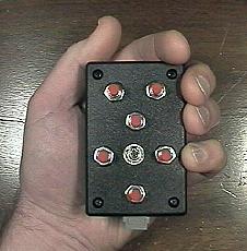
The handpaddle has four momentary-on
buttons that move the scope in altitude and azimuth. The center switch selects
between fast halfstep slewing and smooth slow microstep centering.
The upper two momentary
switches select different actions based on the software's current handpad status.
'Left' is the left mode key, and 'right' is the right mode key.
Handpad mode can be:
- off: mode switch does nothing
- init auto on: pressing either the left or right
mode buttons inits the next available init, for instance, if init 1
already accomplished, then init 2 done, if all inits done, then closest
init to the new init is replaced by the new init
- init 1: pressing either the left or right mode
buttons does an init # 1
- init 2: pressing either the left or right mode
buttons does an init # 2
- init 3: pressing either the left or right mode
buttons does an init # 3
- polar alignment: steps through the polar
alignment procedure for equatorial mounts – see the section on equatorial
startup
- analyze on: if on, the handpad will save a
position based on input equatorial and current altazimuth and sidereal
time values to the analysis.dat for later mount error analysis
- guide on: pressing the left mode button puts the
hand paddle into guide mode, where the push buttons act to move the scope
very slowly in right ascension and declination by adding or subtracting
from the current tracking rate - speed is set by GuideArcsecSec in the
config.dat file - moving the switch momentarily to the right ends guide
mode, and causes drift values to be calculated, put into use, and
displayed - These drift values are used to null out any temporary residual
drift due to imprecise initialization of a portable setup or imprecise
mount construction, then the scope is moved back to the original Ra, Dec
coordinates
- guide stay on: as 'guide on' but the scope stays
put, adopting the new Ra, Dec coordinates of wherever the guiding
corrections took the scope
- guide stay rotate on: when turned on by a press
of the left mode hand paddle button, the program will rotate the hand
paddle buttons by the guide rotate angle, which is slaved to the field
rotation angle
- guide drag on: drift or drag values from the
config.dat file are added to the current drift when the left mode button
is momentarily pressed, and subtracted from the current drift values when
the right mode switch is momentarily pressed; this is for knife edge
autoguiders that rely on the guide star being constantly dragged back
across the knife edge
- scroll tour: if the left mode button is pressed,
this will cause the scope to continuously move through the scroll file; to
stop move press the right mode switch or press any key on the keyboard
- scroll auto tour: if the left mode button is
pressed, this will cause the scope to continuously move through the scroll
file, repeating the scroll tour endlessly; to stop move press the right
mode switch or press any key on the keyboard
- grand tour: the mode switch moves forward to the
next object in the data file, or backwards to the previous object,
depending if the left or the right mode button is pressed
- record equat: the mode switch will write the
current scope equatorial coordinates to the record.dat file when either
left or right mode button is pressed
- toggle track: the mode switch on the handpaddle
can be used to turn tracking off and on (left button = on, right button =
off)
- FRFocus mode: where the mode buttons
actives/deactivates FR and focus motor control, where the up/down controls
the field rotation motor and the CW/CCW controls the focus motor
The software has gone through
several reincarnations, starting as 6502 assembly code for the Commodore 64,
when the Commodore 64 first came out (I bought my Commodore 64 for at the time
incredible sales price of $600, and with no floppy or tape drive, and had to
reenter my programs everytime I turned the computer back on!). Unfortunately,
the stalwart 2 megahertz 6502 processor could only muster recentering the
object every couple seconds. The dream of an inexpensive amateur built altaz
drive seemed far away, until the AT class machines arrived. The code was then
rewritten in C. Later, the code went through its C++ object oriented life on a
386. Now, in interests of making the code as universal and easy to port, the
code lives in ANSI C. Functions that are directly tied to low level hardware
such as the parallel port and bios clock, use pointers to access the
appropriate memory locations. For non-DOS machines, some modification of these
parts of the code will be necessary.
The servo version of the
software was started in May 2001.
The program is based on the
popular two-star conversion algorithm, based on an Feb
'89 Sky and Telescope magazine article by Toshimi Taki, to translate between
altazimuth and equatorial coordinates. The scope need only be accurately
aligned on two widely separated stars using a high power reticle eyepiece;
there is no need to level the base. The scope can also be initially set on a
planet, say, soon after sunset. After a couple of minutes of microstepping
recentering, the scope is initialized on the same object again. The scope will
continue to track the object, keeping it in the eyepiece field of view for an
hour or two.
In addition, the program will
use a third initialization point, for more accuracy than the
two star initialization would otherwise give. Any of the three
initialization positions can be reinitialized as often as wanted. All
init positions are saved to a file for later analysis.
The conversion algorithm
allows the input of mount construction errors. For instance, one altitude
bearing may be a bit lower than its counterpart. Normally this would cause a
pointing error, but the conversion algorithm will compensate once given the
amount of the error. The program can refine the altitude angle
based on the initialized positions. Per the original Taki routine, the
starting azimuth can be any number. Now the starting altitude only needs
to be set to within 10 degrees or so. This altitude offset algorithm was
contributed by Dave Sopchak. This is the 'Z3' error (offset in elevation
between the optical axis and the mechanical axis) so named by Taki.
Taki's Z1 (axes non-perpendicularity) and Z2 (offset in horizon between the
optical axis and the mechanical axis) errors are also calculated after at least
three initializations are done.
The software is event driven
by either keyboard or hand paddle input. If no events occur, then the scope
moves to the current equatorial coordinates. If the coordinates remain
unchanged, the scope tracks. If new coordinates are entered, the scope slews.
Slews can only be interrupted by pressing or releasing a button on the handpad,
and by the keyboard, and by the altitude or azimuth limits if the interrupt
driven halfstepping option is turned on. Tracking should be paused if
hot-keying out to another program. When the program is exited, the scope's
altazimuth coordinates are saved along with any initialized positions.
The software handles backlash
and handles periodic error correction, or PEC, for both axis. A 'guide'
function is also included so that guiding for a minute or two nulls occasional
tiny residual drift. Drift can be manually entered in both equatorial and
altazimuth coordinates.
scope.exe -
the executable program
*.c, *.h - source code
config.dat -
the configuration file
bstars.dat, messier.dat, are object catalog files along with other *.dat
files too numerous to mention
*.scr -
scroll files
*.cdf –
comet definition files that include comet positions and equatorial drift values
inithist.dat -
a history of all initializations, in degrees (Ra, Dec, Alt, Az,
Sidereal Time, reason for init)
analysis.dat
- a file of recorded positions triggered by the handpaddle that is used for
later mount analysis
analysis.err
- errors calculated from the analysis file
altazec.dat -
correction file for altitude errors vs azimuth (rocker base levelness)
altaltec.dat
- correction file for altitude errors vs altitude (altitude eccentricity, tube
flexure)
azazec.dat -
correction file for azimuth errors vs azimuth (azimuth eccentricity)
pmc.dat - a
file containing corrections used by the pointing model corrections routine
pec.dat -
the file used for periodic error corrections to the motors
guidealt.dat and guideaz.dat - a record of guiding corrections
outguide.dat -
list of exit positions from Project Pluto Guide
input.dat -
a record of all Ra, Dec, and name, that appear in the equatorial input fields
YYMMDDa through YYMMDDz.log,
ie, 000313a.log - observer's log: a copy of the input.dat file, saved at
program exit
record.dat -
recorded scope equatorial scope positions via the handpaddle
encoders.txt
- a recording of encoder threshold violations for each session
trenc.txt -
file containing encoder readings per each microstep for all windings
polealgn.txt –
file containing record of polar alignment procedure results
(a
single blank space must start each line):
Ra_hrs Ra_min Ra_sec
Dec_deg Dec_min Dec_sec name or comment
ie,
12 23 14 33 53 09 test
position
I have a conversion program
available for the asking that will convert Megastar and Sky commander file
formats to scope.exe's data file format.
For scroll file data layouts,
see the webpage on operating the software - subpage scrolling.
Comet file layout (a single
blank space must start each line):
Ra_hrs Ra_min Ra_sec
Dec_deg Dec_min Dec_sec Drift_Ra_hrs Drift_Ra_min Drift_Ra_sec Drift_Dec_deg
Drift_Dec_min Drift_Dec_sec name or comment
ie,
07 14 31 +23 +12 +11 +00 00
+2 -00 -00 -1 31P Schwassmann-Wach
note that drift is per hour
In detail, the sequence of
events for each bios clock tick (which occurs about 18.2 times a second) is:
- add equatorial drift to current equatorial
position,
- update a status field or work with the optional
encoders: either a calculation or a direct write to video memory or
reading the encoders or setting current coordinates to encoder
coordinates,
- check for keyboard event, if none,
- check for handpad event, if none,
- check for IACA event, if none,
- check for LX200 events and process all
accumulated commands since last bios clock tick, but if none,
- check to see if field rotation motor needs
pulsing,
- then move to current equatorial coordinates by:
- calculate new altazimuth coordinates based on new
sidereal time that was calculated when bios clock tick occurred,
- find difference between current altazimuth
coordinates and newly calculated altazimuth coordinates,
- find distances to move in each axis and decide
between microstepping or halfstepping, if microstepping,
- then check for backlash, if none,
- then spread microsteps over the bios clock tick
by dividing # of microsteps into MsTicksRep, the count of PWM's per bios
clock tick: if microsteps exceeds MsTicksRep, then reduce # of microsteps
per fullstep up to halfstep, and if necessary, halfstep pulse the motors,
- continuously generate PWMs, checking for bios
clock tick at end of each PWM: a PWM consists of outputting to parallel
port an already calculated array of ons and offs to the stepper motors'
windings,
- when bios clock tick occurs, PWMs end and new sidereal
time is calculated,
- the field rotation motor calculations are done at
the start of the microstepping function, and at the end of every PWM, a
check is made to see if the field rotation motor needs pulsing,
- current altazimuth coordinates updated to reflect
# of microsteps that actually occurred, current altitude coordinate
updated to include refraction,
- current altazimuth coordinates updated to include
any backlash compensations already moved,
- current altazimuth coordinates updated to include
PEC based on steppers rotors' position,
- current altazimuth coordinates updated to include
altazimuth drift,
- current altazimuth coordinates updated to include
any guiding motions
German
Equatorial
The program handles GEM
mounts and their required meridian flip. It does so by changing the altitude
and right ascension in low level functions. Right Ascension is rotated by 180
degrees. The altitude is mirrored across the pole so that a declination
of 80 is an altitude of 100 degrees .After a flip, the altitude will read in
the range of +90 to +180 to higher values (-90 to -180 and lower if in the
southern hemisphere). The Declination and Right Ascension will be calculated
and displayed correctly. The hand paddle buttons are not automatically swapped
in case autoguiders are wired in. However, the hand paddle buttons can be
swapped after the GEM flip by selecting the menu option 'flipbuttons' in the
control section.
To do the flip automatically:
- 1.Either turn on autogemflip in the config.dat file, or
via the menu option: motors | autogemflip. The meridian flip will
occur automatically, starting with a move to the pole, followed by the
move across the meridian, ending with the move from the pole. You
will have to cancel each slew in sequence if you wish to abort.
- 2.Or, select the menu option: move | gemflip.
To do the flip manually:
- 1.Turn off tracking.
- 2.Select the GEM flip menu option.
- 3.Position the telescope in declination so that
the tube is roughly pointing at the celestial pole, for instance, a
declination of 80+ degrees (-80 degrees if in the southern
hemisphere).
- 4.If using the hand paddle to position the scope, or
encoders are operational, the Ra and Dec should agree with the equatorial
coordinates displayed before starting the GEM flip.
- 5.Move the scope 180 degrees in azimuth or 12 hours in
right ascension.
- 6.Move the scope across the pole in Declination until
the scope is roughly pointed properly.
- 7.Re-center the object.
- 8.If the hand paddle was not used to position the
scope, or no encoders are present, you must do a 'reset to equat' to set
the altazimuth coordinates properly.
- 9.The altitude will display a reading greater than 90
degrees (southern hemisphere users will see a reading below -90 degrees),
and the Declination will display a reading less than 90 degrees (southern
hemisphere users will see a reading greater than -90 degrees).
- 10.Tracking and goto
functions can be resumed.
- 11.Hand paddle up down
buttons can be reversed if desired by going into the menu section: control
and selecting the flipbuttons option.
Program startup and shutdown:
You may start with the scope
on either side of the meridian, and end with the scope on either side of the
meridian. It is preferable to end with the scope on the same side of the
meridian that you expect to start next time with. If you do not, read the
next section.
Synchronizing software and telescope to same side of
meridian:
- 1.turn off tracking
- 2.reverse the GEM flip (if it was off, turn it
on, and visa versa)
- 3.enter appropriate input equatorial coordinates
where the scope is actually pointing (if flip is off, RA should be less
than sidereal time, if flip is on, RA should be greater than sidereal
time)
- 4.do a 'reset to equat'
After the initialization,
typically high power tracking will show two residual errors.
The first is a slow steady
drift, commonly a couple of arcseconds per minute of time. This is caused by
small initialization errors such as not precisely centering the star in the
crosshairs when initializating, and mount errors such as the azimuth and
altitude axes not being exactly perpendicular.
The second is periodic error
caused by the gearing, commonly the worm not being centered on its shaft or
butting the gear properly. This shows as a slow oscillation of the star back
and forth across the crosshairs.
The program has both periodic
error and drift error cancellation features.
The PEC, or periodic error
correction, file consists of two columns. The first is a counter, 0 to 199,
that indicates the index. The index is the resolution or number of steps that
the PEC is divided into. Commonly this is spread over a single motor rotation
or 200 fullsteps, but may be spread over any number of fullsteps. For instance,
spreading the PEC over 400 fullsteps would cover the PEC caused by a double
turn worm. Set the number of fullsteps that a PEC cycle will cover with the
variable FullstepsPerPECArray. Mark a synchronization point on the motor shaft
or the worm shaft that indicates the starting position, corresponding to an
index of 0. Next to the index numbers in the PEC.DAT file are numbers that that
indicates the amount of PEC in tenths of an arcsecond to apply at each index.
For instance, if a single turn worm causes 2.3 arcsecond of periodic error with
the motor shaft at a 45 degree angle, then index 50 would have a value of 23
(assuming 200 fullsteps per motor revolution). See the PEC.TXT file to see how
to enter these values. The altitude PEC comes first, with indexes of 0-199, then the azimuth motor comes with indexes of
0-199. Remember that you have 200 PEC values per axis, no matter
how many fullsteps you spread the PEC over.
"I am Chuck Shaw. I
recently finished converting my 14.5"f/5 dob into
an AltAz system using Mel's plans and software. I concur, it is MUCH more of a
"system" than I ever imagined!!!
I also just went through
coming to grips with nulling out PE and I have a few "lessons
learned" that might be helpful....
1. Use LOTS of power when
running in Guide mode to build Guide.dat I used two barlows stacked into each
other (a 1.7x and a 2.8x and a 12mm illuminated reticle eyepiece and an ~1808mm
scope gives about 720x...... use AT LEAST that much if you can.... (Slightly
defocused blobs are easier to guide with than points anyway!!)... You ARE using
an illuminated reticle EP aren't you??? Do not try to keep a focused image of
the star in the center of the box. Either defocus till the star fills the box,
or put the star in the center of an intersection of two lines, or put it in a
"corner" where its just touching two lines.
Try different techniques to see which works best for you. I found the biggest
source of inconsistencies in my data sets was ME and my poor guiding!!!!!! My
reaction times usually had the wrong direction and were late..... (duh......) :-) Play with the orientation of the handpaddle
also to see if a "fly to" type of guiding is easier.....
2. Use the guide routine
several times to nail the drift as well as possible BEFORE you try to write a
file to capture PEC data.
3. For Azimuth data
collection, be sure and aim the scope due south, near the celestial equator.
This will minimize motion from Alt, and maximize the motion in AZ....
4. Shell out to DOS without
stopping tracking after a Guide run, Do a "copy c:\guide.dat
PE-AZ1.txt", then a copy "c:\PEC.txt guide.dat" (say YES to
overwrite) , then type exit and SHAZAM the scope will slew back to the star you
were guiding on and you are ready for another run!!!!! Name the next file
PE-AZ2,txt, etc...... This allows you to capture
several runs very quickly, and any system config changes between runs are
minimized.
5. VERY CLOSELY inspect for
any "wobble" in your worm bushing. I use 359:1 Byers gears. I had to
make the bushings for the worms and discovered the bushing has a tiny bit more
slop than it should (the clearance is about 0.001 and Byers tells me it should
be about 0.00005). I decided to fabricate a "tailstock" out of a
small aluminum angle and a brass machine screw. I ground a point on the end of
the machine screw and it goes through the bracket and presses into the center
ground dimple in the end of the worm. That made a HUGE difference in obtaining
repeatable data. I think the problem was the worm's wobble was somewhat random.
That, in turn changes the mesh slightly, and that induces PE.... If your worm
is on a shaft with bearings/bushings at both ends, you still need to look for
this!
6. Look at the couplings for
the motor to worm. If they are flexible and you are using the motor bearings to
stabilize the worm at all (if there is slop in the bushings you are in this
category), you need to go to a precision coupling. I bought several commercial
ones and found they were slightly out of round!!!! This in itself introduced PE!!!
Thats OK though, since the Software will compensate
for it.
7. Reinitialize the
motor/worm positions in between runs to make VERY sure that you know what
position corresponds to the 0 position in the guide.dat data I failed to do
this a couple of times and got accurate but skewed curves..... You have to
remember to turn off PEC and then back on after the shafts are positioned !!!!!!
8. Remember the data take
will NOT start at zero unless you time it that way. Do not try to get cute and
time it, just start it and use your spreadsheet program to cut the four runs of
data into separate columns and then move them up/down in the spreadsheet to
line up the steps in each run. Then delete the step number columns (all but the
far left one). Graph the 4 curves and throw out any that are obvious guiding
errors. Then average the rest and you are there!!!
9. Remember after the data
file is copied into a file called PEC.dat to reinitialize the shafts to their
zero position. I keep forgetting to do this!!!! The system also seems to get
lost after a couple of hours of operating.... An occasional reinit of the PEC
alignment takes less than 15 sec and helps "clean up" things. I
should not have to do this but......
I have the sets of curves
from my data takes I can send you. I was having the inconsistencies in taking
data initially, and then the phase skewing till I stabilized the worms too....
perplexing, but a methodical working on each potential source of PE will find
the culprit!!!
The performance of the system
is simply astounding when all is completed..... I agree with Mel that software
timing errors are the least likely culprit. Too many times I wanted to blame
the software for problems but Mel has simply done too good of a job!!!!! It was
ALWAYS something I did!!!! (don'tcha hate it when that
happens!!??) :-)"
Updating the
PEC data on the fly
Much has been done to enhance
the generation of periodic error correction on the fly. The two principal
errors affecting guiding accuracy can be fixed at one time: the periodic error
of the gear that the stepper connects to, and drift. The drift may need
to be tweaked after pointing to another section of the sky.
There are two methods to
choose from: fixup an already generated PEC or generate a PEC from scratch
The PEC in use by scope.exe
can be displayed by using the hotkey 'c'. If you wish to save this PEC to
PEC.DAT, answer yes.
To synchronize the PEC with
the motors, use the handpaddle to move both motors to their respective
synchronization angle, then select 'p' or pec on/off on the keyboard. PEC
is now synchronized with the motors and will remain synchronized unless the
motors stall.
To generate PEC from scratch,
or to to fixup an already generated PEC, put the hand paddle into guide+save
mode, and guide until at least two high beeps and two medium beeps are heard,
preferably until a low beep is heard, indicating that the guide array has been
filled. The higher pitched sound indicates each time the altitude motor
crosses the synch point. It must cross twice in order to generate a full
motor rotation of data. A medium pitched sound is used to indicate the
azimuth motor's crossing of the synch point. Multiple rotations of the
motor will yield multiple PEC analysis files. Better results may be
obtained by focusing on only one axis, then repeating the entire procedure for
the other axis.
If using an equatorial
telescope, or using an altazimuth telescope where one axis is moving very
slowly (altitude axis when on the meridian for instance), then you will have to
either misalign the scope or find another section of the sky where both motors
are moving at a nice rate.
Use the 'u' and 'v' hotkeys
to inspect the just completed guiding corrections. If you wish the
guiding corrections will be saved to PECALTxx.TXT or PECAZxx.TXT files, where
'xx' starts at '00' and is incremented for each file saved. This allows
you to build several iterations of guiding corrections in order to average them
for a more accurate PEC. In addition, the drift should shrink to zero as
it is refined. Use the 'e' and 'f' hotkeys to read in all the PECALTxx.TXT or
PECAZxx.TXT files, average them, then display the results graphically,
including how the pec will look if the averaged files are added in.
Use the 'L' hotkey to reload
PEC.DAT.
Set TestString to
"PreloadGuidexx.dat" to preload guidealt.dat and guideaz.dat upon
program startup. This gives an opportunity to analyze and pull out pec
data from earlier guiding efforts.
Improve
Local Finding/Tracking Accuracy
Slew to a bright known star
near the object.
Select new coordinates by
using one of the data files, or by calling Guide.bat if available, or by
inputing equatorial coordinates manually.
Choose Reset:equat - this will adjust the altazimuth coordinates of the
telescope. Alternatively if you do not wish to change the altazimuth
coordinates (for instance, you are using encoders and are positive that the
encoders are working properly), choose to re-init #1 or #2 or #3 - this will
update the initialization of the scope vs the sky and result in accurate
movements near the initialization points.
Select Coord:equat to enter coordinates of new object to view.
Choose Move:equat
to slew to object.
This nearby slew, if
carefully done, will be accurate to the arcsecond level.
Alternatively, if you know
the distance from one object to another, say, object 'x' is 1 degree north of
object 'y', then center object 'y', and apply the coord:offset equat menu item
then move:equat to make the precise offset movement.
Improving
the initializations - Optimizing Goto and Tracking
Most amateur telescopes point
haphazardly. Sometimes the object is in the field of view and sometimes it's
nowhere to be found. A telescope must be precisely built: axes perpendicular,
round altitude bearings, matched rocker side bearing points, flat rocket base,
rigid tube assembly, and coincident optical and mechanical axes. The most
popular form of telescope, the manually pushed Dobsonian with teflon and formica bearings, does not require this kind of
precision construction. Consequently, pointing accuracy generally falls between
1/4 degree and 1 degree. In addition, in a motorized scope, the motors and gear
train introduce backlash and periodic errors in pointing and tracking.
Consistent pointing to one arcminute is a worthy goal, giving confident
centering of objects on small CCD chips and in high power eyepieces. If
necessary, offsets accurate to arcseconds are easily obtained by first
centering on nearby objects. Blind across the sky arcsecond accuracy enters a
new realm. Here a whole barrel of corrective factors must be actively
calculated and applied. While necessary for large professional scopes, this
level of arcsecond accuracy is not needed by the serious amateur.
Errors to either eliminate by
better design and construction, or by software compensation in order of
importance and in order that they should be tackled:
ü
gear backlash
ü
gear periodic
error correction (called PEC)
ü
for stepper
motors, physical variations in the quarterstep spacings over the sequence of windings
(called QSC for QuarterStepCorrection)
ü
drift
ü
atmospheric
refraction
ü
axis misalignment
(one side of the rocker is higher than the other) (called Z1 or axis
misalignment)
ü
discrepancy
between the optical and mechanical axis in the horizontal axis (called Z2 or
azimuth offset)
ü
discrepancy
between the optical and mechanical axis in the vertical axis (called Z3 or
altitude offset)
ü
altitude vs.
azimuth error correction (dobsonian rocker base levelness) (called ALTAZEC)
ü
altitude vs.
altitude error correction (tube droop, altitude bearing unevenness) (called
ALTALTEC)
ü
azimuth vs.
azimuth error correction (azimuth drive gear eccentricity) (called AZAZEC)
ü
residual errors,
captured as pointing model corrections (called PMC)
My software compensates for
gear backlash. Move the motor in one direction until all backlash
is taken up. Note the displayed Current Altitude or Azimuth value. In daylight, sight through the telescope at a distance sharp edged
landmark. Carefully and slowly move the motor in the opposite direction
until the telescope begins to move. Subtract the updated Current Altitude or
Azimuth value in degrees to get the backlash value. Multiply by 60 and enter
the resulting value in arcminutes in the configuration file.
My software offers extensive
periodic error correction, called PEC. See the PEC webpage to learn how to map
the periodic error and how to correct for it.
Telescope coordinates are
translated to celestial coordinates using an alignment model. This model will
be very simple in the case of an equatorially aligned telescope where altitude
matches declination and azimuth matches hour angle (local sidereal time minus
right ascension). For altazimuth telescopes, the modeling is more complex.
Lesser used models include algorithms such as matching angular separation, and,
more simply, tracking via automated following. More commonly used is a model
based on spherical trigonometry formulae. These formula call
for entering the latitude and longitude of the observing location, precisely
leveling the base, then finding stars using an accurate clock.
I use the model popularized
by Taki. He uses a matrix of directional cosines to convert between telescope
and celestial coordinates. The telescope pointing values are calculated from
the telescope's altitude and azimuth, and time at the moment the object is
precisely centered in the field of view. For instructions on how to initialize
the telescope to the celestial sphere, see the operate software - equat
startup, or, operate software - altaz startup webpages.
Drift is caused by pointing
errors. Positions to track to, or, velocities to track by, are calculated based
on assumptions of how the telescope is aligned to the sky. Inaccuracies in this
alignment will cause the object to appear to slowly drift away from the center
of the field. Drift can be nulled by setting my software in the guide + drift
mode, and following an object for a couple of minutes. Centering the object, then pressing a button on the hand paddle, causes drift to
be calculated and automatically adopted. Use drift nulling to precisely track
an object for long exposure imaging on CCDs or film. Drift will slowly change
as the telescope tracks for hours into a new portion of the sky. Drift should
be set to zero before slewing to new object.
Refraction is caused by the atmosphere, making objects near the horizon appear higher in
the sky than they really are. Don't turn this on unless you have an altazimuth
mount that is reasonably level. Also, don't turn this on until backlash
compensation is working.
One advantage of the Taki
routines is that the azimuth need not be precisely set at startup time. That
is, one does not have to set zero azimuth precisely
north or south. Instead, the routine relies upon the difference between
azimuths. So the starting azimuth can be any value since we need only measure
the change in azimuth as the telescope moves. Unfortunately, the starting
altitude needs to be precisely known. However, by using the idea of matching
the angular separation given by the celestial coordinates to the angular
separation given by the telescope's coordinates, the correct altitude can be
deduced. This means that the starting angle of neither axis need be precisely
known at startup time. The altitude offset is typically done once each evening,
as soon as the two stars are initialized. It is best to use two stars at about
the same altitude with widely differing azimuths. The altitude offset is called
Z3 by Taki. By investigating different scenarios, it is clear that deriving the
altitude offset from two precise star positions is better than averaging
discordant offsets from a group of casually taken star positions.
Z2 is the azimuth offset error, or the difference
between optical and mechanical axis in the horizontal plane. Z1 is the degree of
misalignment between the telescope's two axis. Think
of one side of the rocker arms being higher than the other side: the axes are
no longer exactly perpendicular. Z1 causes a growing azimuth error as the scope
is moved towards the zenith, while Z2 is a constant azimuth error. However, as
the scope is aimed further skyward, while Z2 itself stays constant, the affect
on the scope's pointing is to make the azimuth error appear to grow. The lines
of azimuth shrink as the scope approaches the zenith, so the apparent azimuth
error increases. This mimics the Z1 or axis misalignment closely. Not only
that, but investigating Taki's coordinate translation matrices shows that Z1
and Z2 are tangled and cannot be separated or solved for independent of each
other. Instead, an iterative approach must be adopted, not only in Taki's
routines themselves when converting from equatorial to altazimuth coordinates,
but also in any routine that attempts to analyze sky positions to deduce the Z1
and Z2 errors.
Consider the following graph. Here I derived Z1 and Z2
errors that result if the scope is centered on a star at 10 degrees elevation,
and on a star at 80 degrees elevation. Note that opposite Z2
mimics Z1. The difference between the Z1 and Z2 curves is very subtle,
amounting to a handful of arcminutes at a between elevation. The challenge of
calculating the proper Z1 Z2 is further compounded when considering that real
world Z1 Z2 values are likely 1/4 to 1/2 of those used to generate the graph,
that Z1 and Z2 are likely present in some unknown mix, and, that the accuracy
of azimuth measurements at high elevations is reduced by the cosine of the
elevation. At 80 degrees elevation, measurements will be almost six times less
accurate.
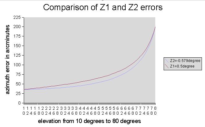
Measure Z1 and Z2 after the altitude offset and
previously mentioned errors have been taken care of. Use a new set of three
stars at about the same azimuth with differing altitudes from close to the
zenith to the horizon - just the opposite of the best way to go about measuring
Z3. Always avoid the equatorial and altazimuth poles for star alignments. These
numbers will not change from night to night and can be measured once and stored
in the configuration file. Changing the collimation, or moving the mirrors, or
doing anything to change the horizontal angle between the optical and
mechanical axis will necessitate re-measuring Z1 and consequently Z2. The Z3 -
Z1-Z2 cycle can be repeated based upon another round of two and three star
initializations.
While it may appear troubling that Z1 Z2 cannot be
more assuredly and accurately determined, because the values are so easy to
substitute for each other, the predictive ability is best served by using Z1 Z2
values that do result in the lowest rms pointing error.
The Z1Z1Z3 errors, the
ALTAZEC errors, the ALTALTEC errors, and the PMC errors all rely on the
analysis file. To view the analysis file, use the menu option graph
analysis. If the analysis file looks OK, you can then proceed to correct
for the next error in turn. The errors must be corrected for in order, though
you may skip any of the error corrections.
To interactively change Z1,
Z2, and Z3 while viewing the results, save a dozen analysis points, then go into
the init - graph Z1Z2Z3 menu option.
Five graphs are displayed:
1. a graph of altitude and
azimuth errors plotted on a 30 degree grid pattern of altitude and azimuth,
where green is altitude and blue is azimuth errors; an error bar up or to the
right indicates that the scope aimed too high in value, azimuth is plotted left
to right from 0 to 360 respectively, and altitude is plotted from top to
bottom, +180 to -180 respectively (areas above +90 and below -90 are for German
equatorial mounts after they have been flipped across the meridian);
2. just
to the right, a vertical graph of altitude vs. altitude errors, where the
altitude errors are plotted based on the telescope's altitude;
3. to
the far right, a vertical graph of azimuth vs. altitude errors, where the
azimuth errors are plotted based on the telescope's altitude;
4. below
the main grid, a horizontal graph of altitude vs. azimuth errors, where the
altitude errors are plotted based on the telescope's azimuth;
5. at
the very bottom, a horizontal graph of azimuth vs. azimuth errors, where the
azimuth errors are plotted based on the telescope's azimuth;
Here's a plot of Tom Krajci's
16 inch - RMS error is about 3 arcminutes:
Looking at the far right
graph, Z1 and Z2 can be analyzed. A tilt in this graph indicates that the Z1,
mount axis misalignment, might be changed.
Users report that once Z3,
Z1, and Z2 are nailed, Goto accuracy across the sky is significantly improved,
placing objects in the center of the field at high powers.
After Z1, Z2, and Z3 are set,
the ALTAZEC and ATLALTEC and PMC correction curves can be added. These
must be either ignored or added in the following order:
Z1Z2Z3 correction
ALTAZEC correction
ALTALTEC correction
AZAZEC correction
PMC correction
General Pointing Model
Corrections, called PMC, can now be analysized and adopted. Generate a
new analysis file by going to the menu option init / purge analysis, then
making analysis points in a grid back and forth and up and down the sky, with
points about 30 degrees apart. Go to the menu option init / graph
PMC. Here you will see the errors displayed. If the errors look
common sense, then you may generate the PMC by using the menu option init /
AnalysisToPMC.
Grand Tour
By putting the hand paddle in
grand tour mode, and loading a data file, the scope can be commanded to move
from object to object in the data file, by merely flicking the hand paddle mode
switch to the left. This is useful for planned evening observations, and
sequences of fields of objects such as galaxy clusters. By flipping the hand
paddle mode switch to the right, the scope will return to the previous object.
To create data files for
grand touring, you can manually edit your own files, naming them with the *.dat
extension. Follow the coordinate layout that you find in bstars.dat and
messier.dat.
You can record positions that
you visit during an observation run by using the handpad mode 'record equat'.
Record a position by flipping the mode switch on the handpad.
You can also record positions
if you use certain planetarium programs. Project Pluto's Guide's positions are
automatically recorded when running Guide from inside scope.exe. Other
programs' output can be run through data converter programs like
ngcscope.
Data files
A number of data files are
available, many of them contributed by amateurs who have built the system.
They include:
BSTARS (24 brightest stars)
MESSIER (messier catalog)
NGC0, NGC1, NGC2, NGC3, NGC4,
NGC5, NGC6, NGC7 (ngc catalog)
IC (ic
catalog)
5MAGSTAR (all stars 5 magnitude
and brighter)
18TO2LOW, 0TO8HIG, 12TO18LOW,
0TO7LOW, 7TO12LOW, 9TO23HIG
A_H_BSC, I_Z_BSC (bright star
catalog)
00000XL and 00000L (first
file is all stars 6.5 mag and brighter north of -40 dec, the second file
consists of stars only with Bayer (Greek) or Flamsteed (Arabic numeral)
designations)
HICKSON (hickson galaxies)
PLANETS (run planets.exe to
get current planet positions)
ARP (arp
peculiar galaxies)
PN19TO23, PN00TO11, PN012TO1,
PN17, PN18 (planetary nebulae catalog)
PALGC (palomar globular
clusters)
constellation files designed by constellation abbreviation
mutiple star files designed by 'MS....dat'
many more files can be found in the file repository of the
scope-drive@yahoogroups.com group
Scrolling
Scroll files are used to move
through a series of scrolling, or 'fly-over' motions, and, are used to automate
initializations, analyses, and other actions.
A scrolling flyover motion is
a smooth microstepping action. By flipping the mode switch to the left and back
to center, the scope will scroll to the next position in the *.scr file, over
the number of seconds shown in the *.scr record. If the switch stays in the
left position, the scope will automatically move from position to position.
This is best used for scans of extended objects or fields such as the Cygnus
Loop, and the Andromeda Galaxy.
Scope.exe can start with a
scroll file. Use the syntax: scope.exe -x <scrollfilename>,
ie, scope.exe -x nan.scr
In addition to the handpaddle
mode switch, hotkeys can also be used:
'H' to bring up hand paddle
modes
'm'
to switch to scroll tour
'S' to load a scroll file
'B' to begin a scroll file
'L' to continue onto the next
scroll action (simulates the leftkey of the handpaddle)
'<' to simulate the
leftkey of the handpaddle
'>' to simulate the
rightkey of the handpadle
As of the
In the scroll file, any line
starting with a semi-colon ';' is ignored.
Here are the available
commands:
- absolute move to altazimuth coordinates: written
as abs_altaz,
- offset move to altazimuth coordinates: written as
off_altaz,
- absolute move to equatorial coordinates: written
as a,
- offset move in equatorial coordinates: written as
o,
- drift values in altazimuth coordinates; written as
drift_altaz,
- drift values in equatorial coordinates; written
as drift_equat,
- initialize position 1: written as 1,
- initialize position 2: written as 2,
- initialize position 3: written as 3,
- initialize position 1 using input equatorial
fields: written as 1i,
- initialize position 2 using input equatorial
fields: written as 2i,
- initialize position 3 using input equatorial
fields: written as 3i,
- slew to a data file's closest object to current
equatorial position: written as f1,
- slew to a data file's closest object to current
equatorial position that is not the same as the current equatorial
position: written as f2,
- slew to a data file's closest object to current
equatorial position that has not been visited in the current session:
written as f3,
- turn tracking on: written as trackon,
- turn tracking off: written as trackoff,
- turn off pause and sound notification when moving
to new scroll entry in auto scroll: written as auto_scroll_alert_off,
- save a position for analysis: written as analyze,
- calculate and remove altitude offset: written as
alt_offset,
- turn on auto scrolling: written as auto_scroll,
- turn off auto scrolling: written as
auto_scroll_off,
- move motors to zero out PEC indeces, written as
move_zero_pec,
- saves current equatorial coordinates, written as
save1;
- retrieves the saved equatorial coordinates,
written as restore1;
- adjust the microstepping speed, written as
msarcsecsec,
- set the handpad mode, written as handpad_mode,
- move in halfsteps: written as hs,
- new equatorial coordinates, written as new_equat,
- new altazimuth coordinates, written as new_altaz,
- prompts for input equatorial coordinates: written
as set_equat,
- prompts for input altazimuth coordinates: written
as set_altaz,
- resets to input equatorial coordinates: written
as reset_equat,
- resets to input altazimuth coordinates: written
as reset_altaz,
- resets to home coordinates: written as
reset_home,
- prompts for an object in the specified data file:
written as data_file,
- prompts for an object in the specified data file
and moves to it: written as move_file,
- displays a prompt on the screen: written as
prompt
Here are the commands'
syntax:
Here's the format for a move to absolute altazimuth
coordinates:
abs_altaz
<AltitudeInDecimalDegrees>
<AzimuthInDecimalDegrees> <TimeForMove> <comment>
ie,
abs_altaz 45 100 0
<comment>
This will move the scope to
altitude of 45 degrees, azimuth of 100 degrees. Since the time is zero
seconds, halfstep slewing will be used. If the time to move allows for
microstepping movement, then the scope will smoothly microstep over the
allotted time to arrive at the appointed position.
For both absolute and offset
altazimuth moves, a value of 9999 means to leave that motor untouched, ie
off_altaz 1 9999 10
<comment>
will move the scope up in altitude 1 degree over 10
seconds, leaving the azimuth motor as is
Here's the format for a move to offset altazimuth
coordinates:
off_altaz
<OffsetAltitudeInDecimalDegrees>
<OffsetAzimuthInDecimalDegrees> <TimeForMove>
<comment>
ie,
off_altaz 1 1 10 <comment>
This will smoothly move the
scope up in altitude 1 degree, over in azimuth 1 degree, over a time of 10
seconds.
Here's the format to enter drift values for altazimuth
coordinates:
dirft_altaz
<DriftAltitudeInDecimalDegrees> <DriftAzimuthInDecimalDegrees>
<TimeForDriftInSeconds> <comment>
ie,
drift_altaz 1 0 60
<comment>
This will enter a drift in
altitude of 1 degree over a time of 1 minute (60 seconds).
Here's the format for a move to absolute equatorial
coordinates:
a <RaHr> <RaMin>
<RaSec> <DecDeg> <DecMin> <DecSec> <TimeForMove>
<comment>
ie,
a 23 0 0 15 10 0 10 <comment>
The A indicates absolute
positioning, here, the scope will scroll to 23:0:0, +15:0:0 over 10 seconds. If
the telescope cannot microstep to the position over time given, it will immediately halfstep slew to the absolute position.
Here's the format for a move to offset equatorial
coordinates:
o <RaHr> <RaMin>
<RaSec> <DecDeg> <DecMin> <DecSec> <TimeForMove>
<comment>
ie,
o 0 0 0 0 10 0 5 <comment>
The 'o' means offset
coordinates, that is, the offset position will be added to the current scope
position to arrive at the new target position, here 0:0:0, +0:10:0, or 10
arcminutes in declination will be added to the current position, so that over 5
seconds, the scope will scroll northward 10 arcminutes.
Here's an example that slews
to a starting absolute position, then scrolls up and down in declination over
various times, ending with a slew to the start of the smooth scroll motions:
a 23 0 0 15 10 0 10 AbsMove10sec
o 0 0 0 0 10 0 5 OffMove10'Dec5sec
o 0 0 0 0 10 0 8 OffMove 10'Dec8sec
o 0 0 0 0 -10 0 7 OffMove-10'Dec7sec
o 0 0 0 0 -10 0 0 OffMove-10'DecSlew
Here's the format enter drift in equatorial
coordinates:
drift_equat <RaHr>
<RaMin> <RaSec> <DecDeg> <DecMin> <DecSec>
<TimeForDriftInSeconds> <comment>
ie,
drift_equat 0 0 0 1 0 0 3600
<comment>
This will enter declination
drift of one degree over an hour (3600 seconds).
Here's the format for initializations:
<init
#> <RaHr> <RaMin> <RaSec> <DecDeg> <DecMin>
<DecSec> <TimeForMove> <comment>
ie,
1 10 8 22 11 58 0 0
<comment>
The '1' means init #1 using
current altazimuth coordinates and sidereal time to equatorial coordinates
10:8:22 11:58:0, the 0 seconds time being ignored.
ie,
2 10 8 22 11 58 0 0 <comment>
Here '2' means init #2, with
the same format as the above init #1 example
or to initialize #1 or #2 or
#3 using whatever coordinates at that moment are in the input equatorial
fields,
1i
<comment>
2i
<comment>
3i
<comment>
after a long slew, some
mechanical systems show slippage such that the object may or may not be
centered; here's an example of how to center a messier object by first moving
to the object's vicinity, then moving to the closest bright star, then after
you center the star and init on it, you move back to the messier object
f1 messier.dat
f1 bstars.dat
2i
f1 messier.dat
Here's the format to remove altitude offset:
alt_offset
<comment>
Here's an example of a scroll
file to automate the initialization process, where the scope is positioned on
Regulus before the scroll file is started, then the observer inits #1 on
Regulus, waits a minute, then inits #2, turns on tracking, then slews to the
neighborhood of Spica, and after centering Spica, inits #2 on Spica, finally
ending with calculating and setting the altitude offset to zero:
1 10 8 22 11 58 0 0
init1Regulus
2 10 8 22 11 58 0 0
init2Regulus
trackon turningtrackingon
a 13 25 12 -11 9 43 0 absSpica
2 13 25 12 -11 9 43 0
init2Spica
alt_offset removingaltoffset
Here's the format for retrieving objects from data
files:
<object
retrieval from data file option> <file name>
notice that a comment is not allowed after the file name,
ie,
f1 messier.dat
f2 messier.dat
f3 messier.dat
Here f1 retrieves then slews
to the closest object to the current equatorial position from the messier.dat
file, f2 retrieves and slews to the closest object as long as it does not match
the inputted equatorial fields, and f3 means to retrieve and slew the closest
object that is not in the input.dat file, a history of all inputted equatorial
values during the session.
Here's an example that
immediately slews (since the time is 0 seconds) to 18:0:0 -24:0:0 then slews to
the closest object in messier.dat, then slews to the closest object that is not
currently inputted, then slews to the closest object that does not appear in
the input.dat file:
a 18 0 0 -24 0 0 0 <comment>
f1 messier.dat
f2 messier.dat
f3 messier.dat
Here's the formats for turning
on and off tracking:
trackon <comment>
trackoff <comment>
Here's the formats for turning off the pause and beep
when moving to a new scroll entry while auto scrolling:
auto_scroll_alert_off
<comment>
Here's the format for analysis:
analyze <comment>
Here's an example that builds
an analysis file, by offsetting 1 hr in Right Ascension, then finding the
closest star in bstars.dat, then analyzing; running this pattern a total of 3
times:
o 1 0 0 0 0 0 0 <comment>
f1 bstars.dat
analyze
o 1 0 0 0 0 0 0 <comment>
f1 bstars.dat
analyze
o 1 0 0 0 0 0 0 <comment>
f1 bstars.dat
analyze
Here's the format to turn on auto scrolling:
auto_scroll
<comment>
Here's the format to turn off auto scrolling:
auto_scrol_offl
<comment>
Here's the format to move the motors so that the PEC
indeces are zeroed out:
move_zero_pec
Here's the format to save the current equatorial
coordinates:
save1
Here's the format to retrieve the saved current
equatorial coordinates:
restore1
Here's the format to adjust the microstepping speed:
msarcsecsec <speed> <comment>
ie,
msarcsecsec 100 <note>
Here's the format to set the handpad mode:
handpad_mode
<mode number> <comment>
ie,
handpad_mode
5 <note>
Here's the format for a halfstep slew:
hs <#of altitude
halfsteps> <# of azimuth halfsteps>
<comment>
Here's the format to set to new equatorial
coordinates:
new_equat
<RaHr> <RaMin> <RaSec> <DecDeg> <DecMin>
<DecSec> <comment>
Here's the format to set to new altazimuth
coordinates:
new_altaz
<NewAltitudeInDecimalDegrees> <NewAzimuthInDecimalDegrees>
<comment>
Here's the format to input equatorial coordinates:
set_equat
<comment>
Here's the format to input altazimuth coordinates:
set_altaz
<comment>
Here's the format to reset to input equatorial
coordinates:
reset_equat
<comment>
Here's the format to reset to input altazimuth
coordinates:
reset_altaz
<comment>
Here's the format to reset to home coordinates:
reset_home
<comment>
Here's the format to select an object from a specified
data file:
data_file
<file_name>
Here's the format to select an object from a specified
data file and move to it:
move_file
<file_name>
Here's the format to display a prompt on the screen:
prompt <prompt_string_to_display>
Here's an example to build a ALTAZEC file (altitude vs azimuth, or rocker base
levelness error correction file). Start by aiming the scope at an
elevation of about 45 degrees, then do the first scroll action which will move
the scope to a 5th magnitude star, then precisely center the star using high
powered crosshairs, and do the next scroll action to analyze the
pointing. Next, move the scope to the east about 5 degrees and repeat the
scroll actions. Repeat this pattern of move, grab nearest 5th magnitude
star, center it, and analyze it, as many times as desired:
f1 5magstar.dat
analyze
hs 0 6000 <comment>
f1 5magstar.dat
analyze
hs 0 6000 <comment>
f1 5magstar.dat
analyze
hs 0 6000 <comment>
f1 5magstar.dat
analyze
hs 0 6000 <comment>
f1 5magstar.dat
analyze
hs 0 6000 <comment>
f1 5magstar.dat
analyze
Here are some scroll file
examples to help with portable scopes, by Tom Krajci:
I had a blast over the
weekend observing in the
Woe to us portable telescope
users! It's next to impossible to reassemble the scope (especially
plywood/truss tube scopes!) the same way every time you take it to an observing
site. Mel's software gives us great capabilities to correct for mount/pointing
errors, but how should we use the software to quickly and correctly analyze the
mount pointing errors?
Here's what I have come up
with:
1. Set up the mount the same
way, as closely as possible (for example - same leg of the ground board
pointing due south, bubble level the base with reasonable care.)
2. Do a two star alignment
the same way, every time...taking advantage of your mount's 'sweet spot.' (From
previous testing of your scope, and comparing observing
site lat/long to the 'derived' lat/long from 2 star init's...you should have
found certain altitude/azimuth combinations for two star alignments that give
you good results. For example, I like to use this scroll file for alignment:
trackon
abs_altaz 30 200 0
f1 00000000.dat
1i
abs_altaz 30 320 0
f1 00000000.dat
2i
altoffset
trackoff
When it works right I get
repeatable 'derived' latitude that is within 0.01deg of the site's actual
latitude.
3. Do a quick pointing
analysis of stars at 180 az, at varying altitudes.
Here's a scroll file I use:
trackon
abs_altaz 25 180 0
f1 00000000.dat
analyze
abs_altaz 40 180 0
f1 00000000.dat
analyze
abs_altaz 55 180 0
f1 00000000.dat
analyze
abs_altaz 70 180 0
f1 00000000.dat
analyze
trackoff
Examine your pointing errors
graphically...you will probably find that you need to tweak the value of Z2 to
minimize the changing azimuth error that crops up at various elevations. Last
night, during a calm spell, I got 0.5 arcmin RMS pointing error for my four
star pointing analysis once Z2 was nailed to the nearest 0.01 degree. I find
that Z2 varies a little bit every time I put the scope together...so this 'four
star Z2 analysis' is needed to tune the pointing correction model. I also find
this is a good way to quickly check to see if your step size in altitude is
correct or not...if correct you'll get small/consistent/equal altitude errors
at different altitudes...if step size is wrong, there will be a trend obvious
in the graph...as you move higher the scope consistently points too high (or
too low)..and the the higher the altitude the larger
the error.
Hope this helps,Tom Krajci
Setting
Backlash Values by Jerry Pinter
Be sure to accurately (within
an arcminute or less) determine the exact amount of backlash for each axis. Use
a laser pointer attached to the scope, projecting a dot of light onto a wall.
Start with both backlash settings (in scope.cfg) equal to 0. Using the handpad,
move at slow speed for awhile in one direction, enough to takeup any backlash,
stop, then read the altaz coordinates from the screen. Then reverse the motor
direction on the handpad and stop immediately when the scope starts moving.
Read the new altaz coordinate to determine the amount of backlash (in degrees).
Repeat this several times and use the average value for each axis. Convert this
to arcminutes and enter into scope.cfg. If one does not have a laser pointer,
one can focus a cross-hair eyepiece on a stationary object on the horizon
(house, tree, etc) to determine when the scope starts to move. The encoders
could also be used if their precision is high enough. After entering the
correct backlash parameters into scope.cfg, repeat the backlash test using the
laser or encoders.
The scope should now "take up the slack"
when direction is reversed during goto and tracking. For example, watch the current coordinates
altazimuth display, along with the motor's display. You will see backlash either at zero or at
maximum. Turn on tracking, and after a
few moments to ensure that backlash is taken up, use the handpad to reverse
direction. You will see the backlash in
the motor display taken up in the opposite direction. When the button is released, you will see the
backlash reverse takeup in the motor display, and observe that the current
altazimuth coordinate for that motor remains unchanged during backlash
takeup. This is the key to backlash
compensation: even though the motors are spinning fast to take up the backlash,
the scope is not moving with respect to the sky and thus the altaz coordinates
do not change in value. Without backlash compensation, prior to every change of
direction, the motors will spin and Scope II will think the scope is moving
(and thus change the coordinates on the screen). However the scope with respect to the sky is
not moving yet. This creates errors in pointing accuracy. Backlash can cause
serious slewing, finding and tracking errors, especially if the backlash is a
significant portion of the field of view.
For example, my (Jerry Pinter's) Cookbook CCD f.o.v.
is about 15 arcminutes on my scope, and my backlash is about 7 arcminutes. Thus
if I think I have an object nearly centered, without backlash compensation it
may actually be 7 arcminutes off-center (depending on which way the motors last
spun) which could be off the edge of the chip! Another problem is when doing
initializations or "resetting" off a nearby bright star, if backlash
is not compensated, then the scope may be pointing in error by the amount of
backlash. Also, when tracking an object for CCD imaging, if the backlash is not
compensated, then the object will drift across the image before the backlash is
taken up. With backlash properly compensated for (as described above),
everything is taken care of automatically. Scope II knows exactly where the
scope is pointing during initialization, resets, and slews. When the scope
slews to an object, the object will land on the CCD chip, and tracking will
start immediately after the motors take out the slop, leaving the object in the
same place within the field of view. It's important to have the scope balanced
(alt axis) since any imbalance will tend to make the backlash appear only in
one direction, which will screw up the backlash compensation.
The computer controlled
telescope can accept autoguider input via two methods:
1. LX200 protocol: scope.exe knows about the guiding commands available in the LX200
communications protocol. Simply hook up the serial port from the guiding
computer via a null modem cable to the serial port being used as the LX200
communications port on the computer running scope.exe. Martin Niemi's
superb quickcam autoguider will do this very inexpensively - see
http://www.ameritech.net/users/mniemi000/auto.html
2. Relay box: The autoguider needs to supply a relay for each direction,
or, a +5 VDC TTL signal for each direction, or, a serial connection sending
LX200 protocol commands.
If using a relay box, wire
the interface circuit such that when a relay closes, a
+5VDC TTL signal is supplied as follows:
If using a control signal,
tie the control signals so that the control signal going to logical high raises
the input voltage to a +5VDC level as follows:
(this
scheme mirrors the four direction buttons on the hand paddle)
up
or north: to pin 13 of the parallel port, down or south: to pin 12 of the
parallel port, left or counterclockwise: to pin 10 of the parallel port, right
or clockwise: to pins 13 and 12 of the parallel port.
See following webpage for how
Lenord Stage hooked up his SBIG SVD autoguider to the hand paddle:
http://www.dreamwater.com/biz/svdgoto/handpad.htm
Here is how Juan Herrero
hooked up his SBIG ST4 autoguider to the hand paddle:
Purchase a 2 female to 1 male
phone wire adapter. Plug the male side to the control board..
Plug the hand paddle to one of the females. The other female will be for the
ST-4. Purchase a phone wire with a male plug at one end to plug into the 2 to 1
adapter at the control board. At the other end
of the wire. Install the correct computer plug to connect to the ST-4. You need
to install 2 small signal diodes in two of the wires. Install the 2 diodes
inside the computer plug.
The wire assignment is as
follows:
ST-4 action HAND
PADDLE PARALLEL PORT ST-4 pins
-----------------------------------------------------------------
+5v
white
n/a ----------------------- 11, 5,
14, 8
-Az
yellow
10 ----------------------- 10
+Az
green
12 ---------|<|----------- 4 *
+Az
black
13 ---------|<|----------- 4 *
-Alt
green
12 ----------------------- 7
+Alt
black
13 ----------------------- 13
* -----|<|----- This
symbol represents a diode and they are a must for thing to work.
Both the hand paddle and the
ST-4 can be operated at the same time although conflicting simultaneous signals
can be sent to the PC in this fashion, resulting in unpredictable actions.
To operate:
- Put the telescope control program hand paddle
mode into one of the guide modes. Set the speed of the guiding
corrections by adjusting the microstepping guide speed.
- Orient the autoguider by rotating it so that the
autoguider's up and down correspond to the telescope's autoguider.
- Calibrate the autoguider.
- Initiate guide corrections by the telescope
control program by momentarily flipping the hand paddle mode switch to the
left and then center the switch.
- Start the autoguider.
All guide functionality
continues to exist with the autoguider on. For instance, in guide+stay
mode, flipping the hand paddle mode switch momentarily to the right will
calculate drift, and null the telescope's drift. Immediately re-initiate
telescope control program guiding by momentarily flipping the hand paddle mode
switch to the left and then center the switch. In guide+record mode, a
record is kept of the autoguider's corrections.
The hand paddle can continue
to be used. Pressing a direction button will add its guiding correction
to the autoguider.
Guide arrangements include:
Ø
piggyback guide
scope
Ø
off-axis guider
Ø
intercept guider
Ø
built-in guider
chip ala ST7, ST8
Interfacing
with other programs
To use Guide, a planetarium program by Project Pluto
(Bill Gray):
1. Simply select 'guide.bat'
option from scope.exe's menu. Make sure that the 'wguide.exe' program is in
c:\guide.
Guide will show you where the
scope is pointing, and upon exiting Guide, Guide's last coordinates will be
displayed in the Input equatorial fields. Select move to input, or reset to
input.
2. To run concurrently with
Guide6.exe, the Win95 version of Guide, configure Guide6 by going to Settings,
then Scope Control. Select an unused comm port, and pick 'altaz'. You
will see a new drop down menu option appear, "Scope Pad".
Select it. Be careful not to move the mouse as the cursor's position is
used to send coordinates. To send coordinates from guide6.exe to
scope.exe, select 'slew scope' on the scope pad menu. To receive
coordinates into Guide6.exe from scope.exe, select 'slew guide'. To send
coordinates from scope.exe to guide6.exe, use the hotkey '8', to receive
coordinates into scope.exe from guide6.exe, use the hotkey '7'.
Communicating With Other Programs
There are several methods to
communicate with other astronomical software such as planetarium and control
programs.
- via explicitedly calling the DOS version of
Guide
- via the serial/modem port using lx200 protocol
commands
- via agreed upon slew files
- via the IACA
Calling the DOS version of Guide via the menu option
'guide.bat' or the hotkey '`' (left apostrophe), does the following:
- rewrites the startup.mar file that Guide uses to
set its startup position
- exits to DOS and calls guide.bat, which launches
Guide
- upon Guide's exit, Scope.exe reads startup.mar
to ascertain the last coordinates that Guide used
- these coordinates are placed in the input
equatorial fields
Using the serial port to read and write lx200 protocol
commands:
This is available if the
lx200 serial port is set to 1 or 2 in the config.dat file.
Realtime display of lx200
commands processed and the character buffer is available if the menu option
display LX200 is turned on.
Use a serial full null modem
cable adapter to connect between the two serial ports.
Set the ports to 9600 baud, 8
databits, 1 stop bit, no parity.
It may be possible to use the
modem. See http://www.ghg.net/cshaw/modem.htm for
details.
Scope.exe can also communicate via two agreed upon
files, using menu selections read
slew and write slew or hotkeys '7' and '8'.
These files are located
typically in the controlling planetarium program subdirectory, pointed to by
the config.dat's InterfacePath variable, ie, c:\guide\
The file that is used to read
in coordinates from the controlling planetarium program is called slew.dat and
has two lines with the following format:
R
<Ra degrees>
D
<Dec degrees>
The file that is used to
write coordinates to the controlling planetarium program is called slew_out.dat
and has one line with the following format:
R
<Ra degrees> <Dec degrees>
Any controlling program can
thus add a little software to communicate with Scope.exe in this manner.
Finally, the IACA can be used under DOS multitasking
programs such as Windows 3.x:
The Intra-Application
Communication Area is a 16 byte area starting at 0040:00F0 that DOS sets aside to
allow programs to communicate with each other; this area is used to exchange
coordinates between the scope control program and graphically oriented CD-ROM
planetarium programs such as Guide; the planetarium program's coordinates serve
as input to the scope,
the scope program tells the
planetarium program where the scope is pointing; coordinates are assumed to be
precessed to the current date; each program, at startup, sets all coordinates
initially to zero: this way, when non-zero coordinates are found, it can be
assumed that the other program put them there; ie,
long iaca_ra = *(long far*) (0x4f0);
long iaca_dec = *(long far*) (0x4f4);
long scope_ra = *(long far*) (0x4f8);
long scope_dec = *(long far*) (0x4fc);
double scope_ra_in_decimal_hours = (double) scope_ra /
1.e+7;
double scope_dec_in_decimal_degrees = (double) scope_dec /
1.e+7;
PCB Testing
Prior to Motor + Computer Hookup
PCB voltage
diagnostic as reference to ground
running software with LED tester, parallel port test:
parallel port output pins to 7408 AND gates:
logical high - 4.98 volts, logical low - 0.15
7408 AND gates to opto-isos:
logical high - 4.60 volts, logical low - 0.47
opto-isos to TIP120:
logical high - 5.07 volts, logical low - 0.21
TIPs:
emitter logical high
- 0 volts, logical low - 0
collector logical high - 0.56 volts, logical low - VCC, eg,
12.3
base logical
high - 1.25 volts, logical low - 0.08
With the same concerns about
my laptop's parallel port, here's how I tested my
board. Starting with the driver board powered on and disconnected from the
laptop, motors and handpad connected:
#1 Using volt meter, Black
wire of multi-meter to Ground probe parallel pins with red wire looking for
voltages higher than 5v, there should be none.
#2 Using a milli-amp meter,
ground -> 100ohm resistor -> Black wire of meter, probe parallel pins
with red wire recording milli-amp reading for each pin
A) Pins 1 -9 should show very little to
no current (Depending on invert option) * See Note 1
B) Pin 10 should show 50 milliamps only
when Hand pad Left, Upper left, or Upper Right option button pressed * See note
2
D) Pin 11 should show 50 milliamps only
when Slew Speed switch on
E) Pin 12 should show 50 milliamps only
when Hand pad Down, Right, Or Upper Right option button pressed *see note 2
F) Pin 13 should show 50 milliamps only
when Hand pad Right, UP, or Upper Left option button
pressed *see note 2
G) Pins 14 -17 should show very little
to no current (Depending on Options)
H) Pins 18 - 25 should show no current
#3 using a milli-amp meter,
+5vdc -> 100ohm resistor -> Red Wire of meter, probe parallel pins with
black wire recording milli-amp reading for each pin
A) pins 1-9
should show very little to no current (Depending on Invert option)
B) Pin 10 should show 15.6 milliamps
with no hand pad buttons pressed * see note 3
C) Pin 11 should show 15.6 milliamps
slew speed switch off
D) Pin 12 should show 15.6 milliamps
with no Hand pad buttons pressed * see note 3
E) Pin 13 should show 15.6 milliamps
with no Hand Pad buttons pressed * see note 3
F) Pins 14 -17 should show very little
to no current (Depending on Options)
G) Pins 18 - 25 should show 50
milliamps of current
* Note 1
While probing pins 2 - 9 in either step #2
or #3 depending on invert option, Also check to see if
you stepper motors are turning on. In my
case I could here the stepper motor 'Twitch" and it became very difficult to
turn the shaft of the stepper motor.
* Note 2
With the diodes in series and button
pressed, you may only see 44 milliamps of current (If I recall correctly)
* Note 3
Again, with diodes in series and Key
pressed, you may see 6 milliamps of current.
No key press should still be 15.6 milli-amps
Contributed by James Lerch,
http://Lerch.yi.org/atm (James’ Telescope Construction Webpage)
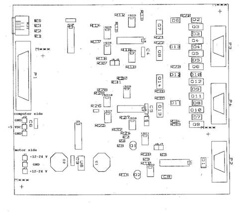
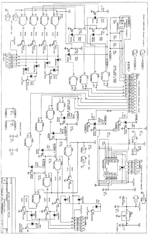
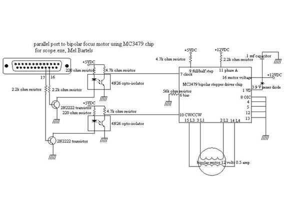
config.dat settings:
set InvertOutput to 0 in config.dat.
Original designed called for
7404 inverters to drive the transistors, hence InvertOutput 1 in the original
config.dat (parallel port output goes high, hex inverters go low, and drive
transistors turn off, hence the need to invert the output).
In the original design, if
opto-isolators were used, then InvertOutput 0 (parallel port output goes high,
hex inverters go low, opto-isolators turn on pulling output low, hex inverters
go high, and drive transistors turn on, hence no need to invert output).
This pcb design uses 7408 and
gates (parallel port output goes high, 7408 and gates go high, opto-isolators
turn off allowing output to return to high, 7408 and gates go high, and drive
transistors turn on, hence no need to invert the output).
heatsinks:
no heatsinks are required on
the power transistors as the software ensures that only the needed current is
sent to the motors, for instance, 1 amp motors typically draw 0.1 amps while
tracking and slewing; a heatsink on the 7805 voltage regulator might be
required if you jumper it so as to power the computer side of the board and
then use the board in poor ventilation or warm temperature (current draw with
motors off at 12 VDC is 0.22 amps), or with higher drive voltages up to 24 VDC;
*** note by Pat Sweeney: I
found that if the motors draw less than 1 amp each the transistors do not
get hot while slewing or tracking. Currents of 4 or 5 amps while ramping up or
down also are OK. If currents of around 2 amps per motor are
expected. insure cooling via a small fan
blowing on the TIP120s If currents much above 2 amps are
expected I would suggest heat sinks But they must be electrically isolated. the collectors are tied to the tab on the TIP120s ***
motor sizes and current limit:
Use unipolar steppers in the
range of 6 to 12 volts with amperage of 0.5 to 1 amps and winding or coil
resistances of very roughly 5 ohms. Smaller and lighter motors will work
also, even for rather large scopes. You can find these in old floppy
drives, for instance. If the motor winding or coil resistance is 1 ohm or
less, then the output power transistors will likely burn out in seconds.
If you need to use more powerful motors of 1 to 3 volts with amperage up to 4
amps, then add either series power resistors, or better yet, install the
current limiting add-on circuit designed by Jean-Charles Vachon.
power/ground connections:
the 6 holes for power and ground go as follows (board
face up with the 6 holes to the lower left):
1. gnd
2. +5 vdc 3. gnd 4. +12
vdc 5. gnd 6. +12 vdc
for complete isolation, use
separate computer and motor grounds, and supply an external +5.0 VDC source for
the computer side or use the +5VDC output from pin 1 of the joystick port DB15;
the vast majority of us will not require this total isolation, instead, tie
computer and motor grounds together, and supply the computer +5 VDC from the
7805 power regulator (U6 - it will get hot supplying both sides of the board so
consider a heat sink if not well ventilated or used in hot clime): do this best
by jumping 1. gnd and 5. gnd
together, then jump the bottom lead of the 7805 to 2. +5 vdc, and finally bring
out two wires from 5. gnd and 6. +12-24 vdc for the
ground and positive power connection respectively;
Be very careful when testing
so as to not risk your computer's parallel port. Use a 6 volt drycell
battery for motor voltage during initial testing.
*** note by Pat Sweeney: I left the computer 5volt supply separate from the 12
volt supply to isolate the parallel port from the drive circuit. If a
catastrophic failure on the drive circuitry occurs there is the possibility of
wrecking the parallel port on the computer. If + 5 volts is not available from
the computer for this then I suggest using a small isolated DC to DC converter
off the 12 volt side. I found that a 12 to 9 volt 250
mA DC to DC converter from JAMECO Part # 153736 for $1.95, and, a 5 volt
regulator will provide the isolation for my laptop. ***
9/25 pin connectors:
circuit board 9 pin and 25
pin connectors are straight (not angled) connectors; use thin flat cable to
connect these to a set of connectors that you have mounted in the electronics
box's face plate;
*** note
by Pat Sweeney: you can mount all but the 25 pin parallel port connector from
underneath on the solder side ***
Hooking up
the stepper windings, by Chuck Shaw
Any stepper motor with 5 or
more leads will do. The stepper will have 4 windings and from 1 to 4
power leads. If a single power lead, then the inputs to all 4 windings
are tied together inside the motor. If 8 total wires, then each winding
has its own power lead.
You can puzzle out the leads
if you use an ohmmeter. For instance, in a 5 lead stepper, the resistance
of a winding to a winding lead will be double that of the power lead to any of
the winding leads. If a 6 lead stepper, 2 windings are tied to a common
power lead. Here, an ohmmeter will indicate which of the 3 leads belong
together. Then for each of the grouping of 3 leads, you can use the rule
of winding lead to winding lead giving twice the resistance of a power lead to
winding lead.
The 6 wires are connected
like so:
1
2 3
|
| |
+----mmmmm----+----mmmmm----+
+----mmmmm----+----mmmmm----+
|
| |
4
5 6
where the "m"s are the windings of the
motor. If you have a volt/ohmmeter,
measure the resistance between each pair of wires:
pair
approximate resistance (ohms)
1-2, 2-3, 4-5, 5-6 40
1,2,3-4,5,6
infinite
1-3,4-6
80
Alternately, you can use a
1.5v battery and a red LED. It will glow dimmer across the 80 ohms than
the 40 ohms. Chances are with your motor one set of 3 is
Now, you have only to figure
out the proper sequence. Here are some additional notes by Chuck Shaw on
this subject:
If a 6 lead motor with red/blue
powered by a white lead, and green/black powered by a yellow lead:
Tie White and Yellow
together, and apply them to +12v
The signals from pins 6,7,8,9
go thru the circuitry to the bases of the transistors to turn them on/off
The 12v goes in via White/Yellow,
and the circuit is completed to ground for a specific coil by setting the base
for that coil’s transistor high.
You can confirm the order
that the pins are pulsed by using the Track test in config.dat (open
config.dat, change the last line in the file to read "Track" rather
than "NoTest" then resave config.dat. Run scope.exe and select a VERY
slow rate). Rig a simple test set up to see which wire is "hot" by
sending the power that would normally go thru the motor windings and send it
thru a resistor and an LED and then to ground. Build 4 of these, one for each
pin output. Pay attention to the LED’s polarity... The longer lead is usually
"+" and the shorter one is the one that attaches to ground. The
resistor should be sized to drop the 12v to 2 v (a 10v drop), assuming a 0.02
amp current thru the LED (V=IR, 10=(.02)(R), R=~500
ohms). Now use TestString = Track and watch the light show!!!! If you want to
watch the output of the parallel port pins directly, the voltage will not be
12v dropped to 2, it will ~5v dropped to 2, so the resistor would be about 150
ohms. Note: you can keep this little test setup hooked up in parallel with the
TIP120 outputs while the motor is running and hooked up too to verify which
windings are being pulsed, and it makes a cool light show when the motors are
driving the telescope too!!!!
(following
diagram by Wayne Topa:)
These pins go to Ground to
'Light' each LED.
9
8 7 6
|
| | |
|
| | |
- |
-| -| -|
-
- - -
L
L L L
<-- (LED's)
+ |
+| +| +|
|
| | |
|
| | |
\
\ / /
\__\_/____/
|
/
\ 1000 Ohm Or 4 each 470 ohm. One on each LED
/ line to
+12V
|
Pins 1-2-3-4-5 to +12V
This matrix assumes the pins
are pulsed in the 6,7,8,9 order:
|
Test
# / Results (Buzz, turn direction, etc) |
6 |
8 |
7 |
9 |
|
1 |
blue |
red |
black |
green |
|
2 |
red |
blue |
black |
green |
|
3 |
blue |
red |
green |
black |
|
4 |
red |
blue |
green |
black |
The idea is to test and
capture the results of the different combinations of pulsing windings.....
The software will pulse one
coil from the Red/Blue pair, then pulse one from the
Black/Green pair, then will pulse the other one from the red/blue pair, and
finally will pulse the other one from the black green pair. Your challenge is
to figure out what the order is within each pair......
For 5 or 6 wire motors you
are done!!! For 8 wire motors the test matrix gets bigger since you also need
to identify the polarity of each winding in addition to its order!!!!!
Here's the color winding
order for Oriental Vexta motors.
1.
red green
blue black
2.
green red
blue black
3.
green red
black blue
4.
red green
black blue
In the end, you will not hurt
anything by hooking up the stepper incorrectly. The motor will buzz or
jump erratically. When you have the leads hooked up correctly, the motors
will move smoothly during microstepping and halfstepping.
A little checkout procedure for you to try:
- Disconnect everything from the parallel port, open config.dat with notepad and change the last
line to read "TestParallelPort" to be able to run the
parallel port test and save config.dat. Then start scope.exe and set
the logical outputs to "high"
- Measure the voltage from the "high"
pins to ground. The high pins are 2,3,4,5,6,7,8,9 and should each
all be about +5v with respect to the ground pins
(18,19,20,21,22,23,24,25). Then set the logical outputs to "low"
in scope.exe and verify the voltages all drop to zero on the previous +5v
pins......
- If all of that was fine, hook up the PCB via the
parallel port cable and turn on the power to the PCB. Do not have
the LEDs or the motors attached to the output DB9 connectors.
- Now, the idea is to set the logical outputs high
as before, and trace the voltages along the PCB to the inputs to the first
chip on the PCB.
Mel's circuit, when the Opto
isolators are added, has the parallel port inputs initially going to a hex
inverter, then to an optical isolator, then to a 2nd hex inverter, then to the
base of the TIP120 transistors, then to the motor. Pat's circuit seems
different. To start with, Pat only uses one Hex inverter and one opto
isolator for each motor instead of two hex inverters and one opto isolator for
each motor in Mel's version. Either system works, just be aware of the
difference... On Pat's sheets 3of7 and 5of7, the parallel port goes to
the Hex inverter first, then the opto isolator. However, on sheets 2of7
and 4of7, the circuit shows the parallel port goes to the opto isolator first,
then the hexinverter...... Either order will work.
The thing to trace out, as
the signal goes into the chip is which pin is connected to that output. If it
was a +5v input, then the output should be 0 v. If the input is +5 and
the putput is 0v, then toggle the parallel port to the other state and the
input should go to zero and the putput should be +5.... Then follow that
output from the first chip to the 2nd chip and do the same thing....
Repeat this for all 8 pins
controlling the motors......
If you trace the signals
across the PCB from the parallel port and all is well, then look to the
transistors. The circuit has +12v going to the motor, then through the winding,
and then coming out and coming back to the transistor, where the transistor
then closes and lets the circuit be completed to ground. You
can test the transistors with your meter set to ohms. The transistor will
be shorted (i.e. no resistance from pins 6,7,8,9 to ground, same config on both
db9 connectors) NOTE, do NOT measure between any
of the "HOT" pins on the DB9 (pins 1,2,3,4,5) to the ground pins
while your meter is set to ohms... or "poof"... :-(
To hook up the LED's, attach one led/470ohm resistor between pin 1 and 6, with
the short lead on the LED attached to pin 6 (which goes to ground). Do
the same for the other LED's (pin2 is +, pin 7 is neg), (pin 3 is +, pin 8 is
neg), (pin 4 is +, pin 9 is neg).
With power ON to the PCB Box,
toggle the parallel port outputs from low to high to low to high and the LED's
should come on and off, etc. With the outputs set high, the
LED's should be on, when they are set to low, the
LED's should be off. If this is backwards, check the config.dat file for
the optical isolator term....
If things still do not work
right on the PCB, using the parallel port test, its a
problem on the PCB. Check to see the orientation of the chips in sockets,
etc... Also follow the +5 voltages from the regulators to see if that
voltage gets to the chips OK. Double check the orientation of the TIP120
transistors to make sure the leads are oriented correctly......
If the parallel port does not
act correctly we need to review the config.dat file settings........
Chris Rowland contributes the following:
I have recently wired up an 8
wire motor made by Superior Electric, it is possible to work out the
connections, even without a meter. The 8 wires are connected to 4 coils and you
need to sort out not just which wires go to each coil but also which coils are
in the same phase and which way round they need to be connected.
(1) Find the pairs of wires
for each coil. There are two ways, one is to connect the wires to an ammeter
and turn the motor. When you have the two ends of a coil you will see the meter
needle move as the rotor moves. The other way is to short two
wires and try to turn the rotor. When you have a coil the motor will be
much more difficult to move and will also feel "notchy". The
difference is obvious.
(2) Sort the pairs into two
sets for the two phases. Connect two windings together in series and measure
the current when you rotate the rotor as you did to find the windings. Try this
for all the other windings, connected both ways round. When you have the two windings
for the same phase, connected in the opposite direction, the current produced
will be zero. It is easy to see this. If you don't have a meter then you can
also use the same trick as above, when the two windings of the same phase are
connected together there will be no additional resistance to movement. You now
have the two windings for one phase but they are connected the wrong way round,
reverse one of the windings. This will give you the common power connection and
the two connections for one phase. (Phase A) Do the same for the other phase.
(Phase B) Connect the common for the two phases to the power and the two phases
to the drivers in the order ABAB. This should work, if you change the order of
the Phase A or Phase B connections then the direction will change, if you are
not in the ABAB (or BABA) order then the motor will not rotate correctly.
I hope this helps.Chris
Rowland
Remember that the software
expects the winding sequence to be A B A- B-, not the A A- B B- that some other
controllers ask for. Here's a diagram contributed by Bob Rubendunst with
the 9 pin connector pin numbers
by Jean-Charles Vachon vachonjc@intlaurentides.qc.ca
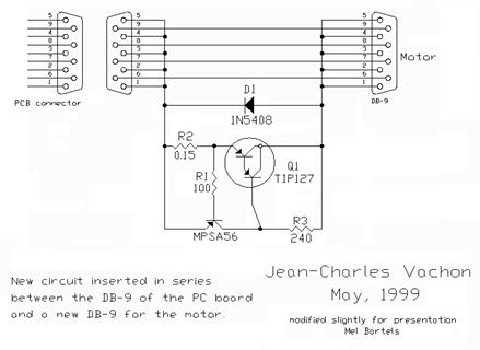
(the
following is Jean-Charles' explanatory text, slightly edited)
In the depicted version, the
240 ohms resistor (R3) is connected to a common point with the TIP127 and diode
1N5408. Since there was no ground connection available, the motor itself was
used as a return to ground. This is not as good as directly returning to
ground, but there was no choice. On a new board this circuit, or a
similar one, can be incorporated on the main PC board, or a ground connection
can be added on the DB-9 connector.
The other version, not depicted,
this resistor (R3) is 1000 ohms and connected directly to ground. This
version is more effective.
Now, the current limit value
is determined by R2, in my case 0.15 ohms for 4 amperes. This resistor
should be a 5 watter. Any current can be chosen and it is calculated the
following way: R2 = 0.6/ desired current. For example in my
case I wanted 4 amperes maximum, so R2 = 0.6/ 4 = 0.15 ohms. In a similar
way, if you desire 3 ampere limitation the calculations are: 0.6 / 3 = 0.2
ohms, and so on.
If you use 24 volts I would
raise R3 to 470 ohms in the first circuit and to 2200 ohms in circuit 2.
Transistor TIP127 does not
heat, but in pure precaution I attached on the alluminium box, I used a medium
size heatsink. I think it is better if used at 24 volts. This depends on
the motors of course.
What the circuit does, is to
limit the maximum current to the value presetted no mater what is the load, so
as I discussed earlier, you will not end with astronomic currents near the 20
ampere mark.
Also see a stepper constant
high current source circuit diagram and article at http://www.siliconchip.com.au/cms/A_30554/article.html
The optional field derotator/focuser
chip can be added later. The circuit board was designed with the SAA1042
in mind. However, the now discontinued SAA1042 has been replaced by the
MC3479 (or ECG1859). Here's a graphic of the MC3479 installed with the
modifications on the pcb:
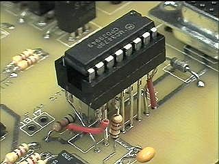
*** following note on how to
hook up the MC3479 and ECG1859 by Bob Norgard ***
Three pairs of wires need to
be reversed to make it function properly with the circuit board, plus a
resistor needs to be added. Get a little daughter board designed to
handle a single IC chip of 16 pins to float above the field derotator
socket. Pins 1 & 2, 15 & 16, 8 & 9 need to
be reversed. Cut 15 pieces of insulated 22 ga solid hookup wire
3/4 inch long. Take a 2k ohm 1/4w resistor and trim its leads to the same
overall length. Solder one end of the resistor to pin #11 of the 16 pin
socket. Additionally, the existing 56k bias resistor may not be optimum
for different motors. Increase the resistance to lower current draw. The MC3479 handles up to 350 ma motors while
the ECG1859 handles up to 500 ma motors. The stepper can handle larger
amperage motors with Chuck Shaw's modifications mentioned below (be sure to
still swap the 3 pairs of leads for the new chips).
Main_Board
ECG-1857 Board
SAA1042 site
|
1*
2*
2*
1*
3
3
4
4
5
5
6
6
7
7
8*
9* |
9*
8*
10
10
11 2K* 11
12
12
13
13
14
14
15* 16*
16* 15* |
* Note lead reversals and
added 2K resistor!!!
I mounted the little board
using 4 stand-offs inside the aluminum box that houses the rest of the drive
circuitry. For testing purposes, I used a Mitsumi Electric M68SP-4 12V/33ohm
stepper salvaged from an old floppy drive. It has 1.8 degree steps.
The chip ran barely warm to the touch.
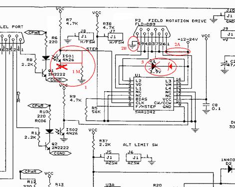
*** note
by Pat Sweeney on the field derotator/focuser portion of the pcb ***
The
schematic and silk screen does show the 3.9 volt zener in backwards. (sorry ) The rest of the circuit is OK. The chip is
configured to drive a 2 phase bipolar stepper motor. (4 wire motor) I tested
the circuit on a stepper that draws 200MA per winding and it seems to work
properly. Only the pins 6,7,8,and 9 are used. Pins
1,2,3,4, and 5 can supply + 12 volts for external transistors to power a stepper
that will draw more than 500MA. Ground for external transistors will have to be
supplied from another location on the board.
- orient the board so that the parallel port 25 pin
connector is to the left
- the tip 120 transistors will face to the bottom,
and the mje 3055 and 7805 voltage regulator will face to the left
- the diodes must be soldered so that their banded
marking matches the diode marking on the pcb
- some capacitors have a long leg - these solder
into the '+' marking
- all the opto-isolators solder in with the
alignment marker to the top of the pcb, (alignment marker is to the upper
left of the indented side)
- make sure you mount the 7408 AND gates so that
the alignment marker is either to the top or to the right
- do not overheat components while soldering:
solder one lead, then move onto the next part, returning later to solder
the next lead
- double check all solder joints before applying
power
- before mounting the 7408 AND gates, apply power
and verify the ground and +5 VDC lines through the pcb, and particularly
at each 7408 AND gate
- use a straight through 25 pin to 25 pin connector
with male ends on each side to connect the parallel port to the pcb
- be careful to not cause a short if using metal
screws to attach the DB9 connectors to the circuit board
- after mounting the 7408 chips and before
attaching the stepper motors, use the parallel port test option of
scope.exe to exercise the output lines and verify with a voltmeter that
the 8 output lines to the 2 steppers are functioning properly
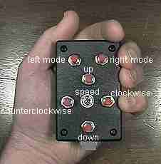
1 handpaddle plastic box
Jameco 18921 (3.1"x2"x.9"ABS) $2.25 or Mouser 546-1591BS-BK
(4.4"x2.4"x1.2"ABS) $3.34
6 push button momentary on
switches Jameco 26622 $.49
1 2-way switch Jameco toggle
21936 $1.09
6 small diodes Jameco 35991
$.40/10
1 RJ11 connector Jameco
124038 $.95
Here's how Ned Smith built
his handpad:
I used the following from
TechAmerica (RadioShack): 910-1075 $15.48 It is a 1 x
2.4 x 3.8 inch enclosure with a membrane
switch pad. It has a 3 x 4 switch array. I cut off one
row to make a 3 x 3. This gives me Up, Down,
Right, and Left. I used the upper R and L corners for the for
the self-centering toggle switch. I only had to add SPDT to handle the two
stepping rates. The membrane switches add about 50 ohms to the circuit which
reduced the voltage at the connector. I used RJ12 connectors for the hand
paddle to PCB enclosure and stepper motor to enclosure.
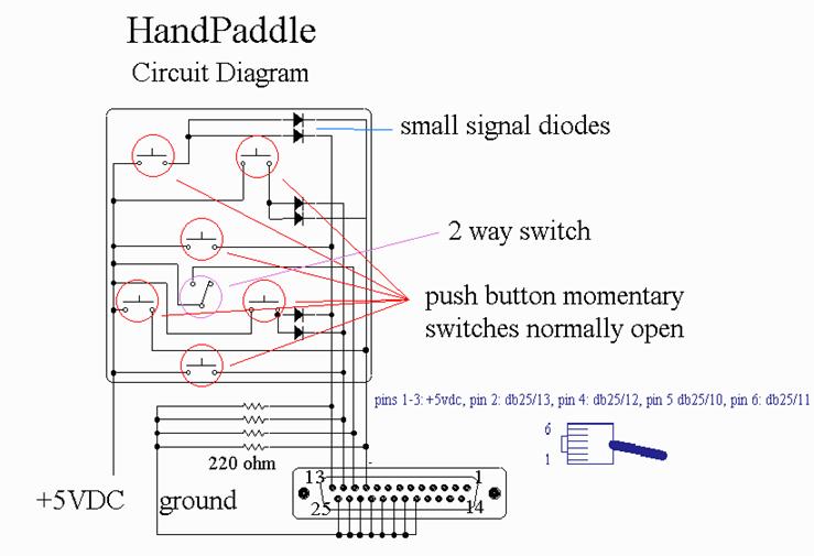
cable: 10 foot length of flat 6 wire Jameco 103448 ($.07/foot)
connectors: (2) RJ11 6p Jameco 79273 $.15
Using RJ11 connector Jameco
124038 with straight through cable (comparing cable ends side by side with
clips up, wiring is the same color sequence from left to right), hookup is:
pin number looking face-on to connector with clip on top:
******
*******************
* rd
wh ye *
* bk gr bl *
*******************
parallel port pin 13 is the yellow wire
parallel port pin 12 is the white wire
parallel port pin 11 is the red wire
parallel port pin 10 is the black wire
+5 VDC is the blue and green
wires
Using RJ11 connector Jameco
124038 with crossover cable, hookup is:
pin number looking face-on to connector with clip on top:
******
*******************
* rd
wh ye *
* bk gr bl *
*******************
parallel port pin 13 is the black wire
parallel port pin 12 is the green wire
parallel port pin 11 is the blue wire
parallel port pin 10 is the yellow wire
+5 VDC is the white and red
wires
Use the part numbers here and
on the printed circuit board - any part numbers on other circuit diagrams do
not necessarily correspond to the pcb.
All capacitors are in
microfarads and all resistors are 1/4 watt: there is a fair degree of latitude
in selecting parts.
Ø
1 C1 4.7/35V
tantalum cap Jameco 33806 $.35
Ø
1 C2 47/35V
electrolytic cap Jameco 31114 $.15
Ø
6 C3-C8 0.1
monolithic cap Jameco 25523 $.15
Ø
1 D1 3.9V/1W
zener Jameco 178765 $.12, Allied 568-0135 $.08
Ø
8 D2-5, D7-10
1N4004 diode Jameco 35991 $.40/10
Ø
4 D6, D11-13
30V/1W zener Jameco 178925 $.08, Allied 568-0045 $.06
Ø
10 ISO1-10 4N35
optoisolator Jameco 41056 $.35 (optional socket Jameco 112192 $.08)
Ø
1 P1 DB25F
connector Jameco 15165 $.65
Ø
3 P2-4 DB9F
connector Jameco 15780 $.49
Ø
2 Q1-2 2N2222
transistor Jameco 28628 $1.10/10
Ø
8 Q3-6, Q9-12
TIP120 transistor Jameco 32993 $.65
Ø
4 Q7-8, Q13-14
MJE3055 transistor Jameco 25857 $.65
Ø
14 R1-4, R6, R10,
R12, R14, R17-18, R26-27, R29, R31 220 ohm resistor Jameco 30470 $.89/100
Ø
1 R5 56k resistor
Allied 526-1666 $2.94/200
Ø
11 R7, R9, R13,
R15-16, R19, R24-25, R28, R30, R38 4.7k resistor Jameco 31026 $.89/100
Ø
4 R8, R11, R32,
R372.2k resistor Jameco 30314 $.89/100
Ø
8 R20-23, R33-36
470 ohm resistor Jameco 31165 $.89/100
Ø
1 RJ11 RJ11
connector Jameco 115836 $.65
Ø
1 U1 MC3479 IC
(replaces SAA1042) Jameco 25216 $5 (needed only if you will be doing field
derotation or motorized focus control)
Ø
1 socket 16 pin
Jameco 37372 $.07 (needed only if you will be doing field derotation and using
the SAA1042 chip; for the MC3479 chip use wire wrap socket Jameco 37410 $1.09
with 2.2k resistor Jameco 30314 $.89/100 as 3 pairs of wires need to be
reversed and one lead replaced with the resistor)
Ø
4 U2-5 74LS08 IC
Jameco 46375 $.25
Ø
4 14 socket pin
Jameco 37161 $.06
Ø
1 U6 7805
regulator Jameco 51262 $.29
Ø
optional TO-220
heatsink for the 7805 Jameco 107297 $.39 (heatsink compound Jameco 167249
$7.95)
Ø
(solder Jameco
141778 $13.95)
The servo system utilizes
encoders to report the servo motor position. External encoders that are placed
on the telescope's two main axes can be added with a slave card. This gives the
ability to detect drive slippage, observers pushing the scope out of position,
and so forth.
For the stepper system,
Bob Segrest has designed a
very small PCB, you can contact him at
bobslan@erols.com.
Patrick Dufour offers a very
compact commercial encoder interface box. See his WebPages at http://www.microtec.net/pdufour/index.htm,
or reach him at Ouranos, 189, rue Du Foin, Saint-Augustin de DesMaures (
Dave Ek's box is a small very
fast reading unit for nominal cost, details at
http://home.earthlink.net/~digicircles
Finally, you can use the encoders from a mouse. Make sure that acceleration and multiplication settings are turned off via the mouse driver. Use the timer method of halfstepping instead of the delay method that temporarily turns off interrupts.
If encoders are used, when
tracking is off, if you grab the scope and move it by hand, the changing
encoder values will update the current altitude and azimuth. When tracking is
on, if the encoders differ from current altitude and azimuth, the situation is
understood to be one of slippage of the drive shafts, or perhaps a wind gust
moving the scope off position. The scope will slew back to the proper position
and resume tracking. Do not intentionally move the scope by
hand when tracking is on if the encoders are on. To illustrate this, the
following is an incident that happened at a recent star party.
Greg Granville writes,
"The 12.5" scope is working very nicely with this setup. I recently
added encoders to the scope. At a star party a few weeks ago, a youngster was
up on a ladder a few steps looking at NGC 4565. When coming down the ladder, he
accidently pushed the scope and caused it to slip on azimuth. He seemed a bit
surprised when the scope responded by automatically moving back to the proper
position!"
The variables
EncoderErrorThresholdDeg and TrackEncoderErrorThresholdDeg control the
allowable difference between scope and encoder coordinates before a reset to
encoder coordinates occurs. There are two variables since a tighter
tolerance during slewing to a target position is often desired compared to the
tracking reset tolerance. Set these to a value that represents at least
one if not two or more encoder counts. At any time the scope can be reset
to encoder coordinates via the 'reset to encoder menu option'. When a
reset to encoder coordinates occur, if you wish encoder these threshold
violations to be recorded, set the config.dat variable MakeEncoderResetLogFile
to 1.
Tonight I installed and
tested flywheels on my stepper motors that drive my sixteen inch scope.
The flywheels make a significant improvement in max speed slewing without
stalling the motors. I can slew at 2.5 deg/second,
and might be able to slew faster, but I'm afraid to slew faster with such a
long tube! ;-)
Based on the reading I've
done in the last few days, I think almost all amateur scopes driven with Mel's
stepper system can benefit from addition of flywheels. Why? The
worm/coupling/whatever that's directly coupled to the stepper motors in amateur
drive systems has a very low rotational inertia...far lower than the inertia of
the stepper rotor itself...roughly the equivalent of the stepper running under
no load. According to the literature I've reviewed (links from Mel's
page) in some (many?) cases steppers don't perform well at the higher speeds
under no-load conditions...resonance freq's are up high, near the speeds you
want to slew at and the motor stalls.
Adding a flywheel (or adding
friction, or adding viscous damping) can lower the motor's resonant frequency,
and improve high speed performance.
My flywheels are very simple
- 1/4 inch plate steel, cut into 2.25 inch squares by hacksaw, with the center
hole drilled with a 1/4 inch drill. Balancing this thing? Put the
flywheel on the drill shank and tap the
shank...the flywheel will fall/settle with the heavy
portion lowest...grind some of that away and test balance again until the
flywheel won't settle into one position over any other. (Balance is not
all that critical here...your steppers won't spin faster than about 10 times
per second at max speed.)
The only
tradeoff? You may have to
ramp up/down the steppers a bit slower now, and perhaps start slewing at a
slower speed, and perhaps lock the rotors after a slew for another .1 second or
so.
There may be another flywheel
improvement in some cases: it might smooth out microstepping
motion. I say that because my motors are making less noise while
microstepping now that I've added the flywheels. That's not proof that
there's smoother motion, but perhaps an indication.
More good
news from experimenting tonight.
Now that I have a flywheel in place, I can use a smaller series resistor with
my steppers (6V driven at 24V). This allows a bit more current...allowing
even higher max slew speeds!
There seems to be a synergy
between: over voltage driving of steppers, flywheels to control resonance
(lower the fundamental frequency), and resistors to keep current within motor
ratings so that resonance is
controlled at lower speeds.
Before the flywheels I had to
use 30 ohms series resistance to keep the motors from vibrating so much (they
would stall at even the slowest speeds). With the flywheels I need only 10 ohms
series resistance. I haven't even had to slow the ramp up/down
speed...which means I can probably use an even heavier flywheel...which may
mean a further increase in slew speed. Yikes! I'm already up to about
2.75 - 3 deg/sec! For now I'm satisfied with slew performance.
Later I may experiment with heavier flywheels.
Stepper motors can run
very quietly. They need not make any more noise when attached to the
scope as when held in your hand. It's common
star party etiquette to run a quiet operation, and you will make a good
impression of your system.
The noise of the switching
stepper motor windings is greatly amplified when attached to metal and wood
mounts. The mount acts as a drum.
To run them quietly, isolate
the stepper from wood and other resonant materials by a thin piece of rubber or
styrofoam or something similar such as a mouse pad
(neoprene). Use nylon screws or nylon bolts to attach the stepper to its
mounting plate, further isolating the screws with rubber grommets. Use a
short piece of automobile vacuum hose to attach the stepper to the input drive
shaft of the gear reducer, leaving a gap of a millimeter between the shafts.
Another suggestion that
receives rave reviews is to mount the motor with rubber standoffs, such as
available from SmallParts.
Paul Shankland suggests using
a PC wrist support made of a long strip of gel material. He goes on to say,
"Cut away the hard rubber base revealing the material (color of vanilla
pudding) underneath, with the cloth left on top - it's a tacky but cohesive
firm gel, - looks like some syntheic blubber, and leaves a faint tacky resiude
- very resiliant, absorbent, but of a resilience that with clamps, would not
let the torque whip the steppers out of alignment. I think PERFECT for the job.
I left the scope drive in my stateroom on the ship, so I took it in to toy with
the damping qualities between bzillion meetings today and PRESTO- amazing
quieting! BEST I have EVER heard!! Or not heard. The motors, about 95%
haphazardly wrapped in the stuff, were sitting on a steel bench which amplifies
noise heinously - but when I powered up the microstepping AND slewing, I
thought the steppers were broken - I could not hear a thing!"
Here's a suggestion from
Jean-Charles Vachon:
"I use a motor with a
2.25 inch square flange and I built aroud it walls leaving about 3/8 to 1/2 of
an inch of space to put the wool.
"A
word about the wool. Ascoustic
wool and insulation wool are not the same.Insulation wool has poor
acoustic properties. Insulation wool is a low density
wool in contrast to acoustic wool which is a high density wool.
"I would have to look
for characteristics for acoustic wool. I do not remember by heart. It has been
a long time I did not work with that. 7 years of retirement start to show. What
I remember is that it is rated in pounds per square yard I believe. For
instance in acoustic treatment we normaly use 3, 3.5 and 4 pounds per square
yard. The heavyer the better is the product for acoustic treatment.If I am not
mistaking acoustic tiles are around 3 pounds per yard which makes them
excellent performer.
"A good way to see if
the wool is firm enough is that it must stand up alone. The ceiling tiles are
rigid enough for that. Now if you put this around the motor particularly
the square flange the motor does not move. I am just returning from the
basement to check that particular aspect, nothing moves.
"I also drive the motors
with a gizmo called Wellnut. This is a rubber thing with 10/32" threads at
one end and a rubber hole at the other. It has 3/4" in length.They are of
all sizes. The one I use can accept, in its hole, the 1/4" shaft from the
motor dirrectly.The rubber is not hard and it makes an excellent universal
joint that will accept and compensate for small misalingment between motor and
worm.
"This is found at your
hardware store and here cost 84 cents only. This is the best thing we found to
couple the motors to the worm, thanks to Allan who made the discovery. I
intend to use them as well for my optical encoders.
"With acoustic wool well
in place the motors should not move.
"To give you and idea of
the results I got here with that : the noise from
the fan of my computer is louder than the motor I have treated with the
wool.
A suggestion from Tom Krajci
on reducing stepper motor noise:
"I've applied poster
putty around my alt and az stepper motor bodies, and
found that it's cut the motor noise by more than half. Poster putty is an adhesive putty that is used to hang lightweight objects
on the wall without damaging wall paper, etc. It's sticky enough to stay in
place, but the best advantage is that it's moldable to just about any shape, so
I can get it into tight corners."
The parallel port is an ideal
interface for controlling telescopes, particularly with laptops in the field.
The parallel port uses 8 bits of output, typically at port address 0x378. On
the 25 pin connector, the 8 bits of output are on pins 2 through 9, from least
significant to the most significant bit. These 8 bits of output are perfect for
controlling the two stepper motors needed to drive a telescope in altazimuth
mode. The parallel port cannot provide or sink large currents directly, hence, 74LS04 hex inverters are used to interface
between the parallel port and the driver transistors.
The parallel port has 5 bits
of input at port address 0x379. These input bits are on pins 15, 13, 12, 10,
and 11 of the 25 pin connector, with pins 11 and 15 being inverted. Pin 15
activates bit 8, pin 13 activates bit 16, pin 12 activates bit 32, pin 10
activates bit 64 and pin 11 activates bit 128. Depending on which lines are
raised high, the values can range from 8 through 248. In addition, the parallel
port has 4 bits that can be either in or out at port address 0x37A. These 4
bits show up on pins 1, 14, 16 and 17 of the 25 pin connector. Bits 1,14 and 17 are inverted. These values when read range from 0
to 15.
For more on the parallel
port:
http://baza.doc.ic.ac.uk/~ih/doc/par/
http://home.rmi.net/~hisys/parport.html
http://www.boondog.com/
http://www.lvr.com/files/ibmlpt.txt
Two methods of motorizing
telescopes are open loop stepper motors and closed loop servo motors with
tachometer or encoder feedback. With an open loop stepper motor system, the
motors are commanded to move: there is no feedback that the movement took
place. Stepper motors move in precise increments of (usually) 200 full steps
per revolution. By conservatively rating the steppers, we can insure that the
motors will never stall. The common dot-matrix printer positions the print head
and paper in this manner. With servo motors we need some sort of feedback to
tell us how the motor shaft is rotating. A tachometer or encoder will give us
this information but at a price of more complex hardware and software. In
practice, both methods work well. For our purposes open loop steppers will be
easier to control over the wide range of scope characteristics and speeds
needed by the altazimuth drive.
Perhaps the name 'stepper' is
a misnomer; this type of motor was originally conceived to run on AC
synchronous power. Instead of using smoothly varying AC, if DC is applied first
to one winding, then to the next, the motor will move in step fashion, hence
the name. When the DC is made to vary synchronously, in our case by a digital
method called Pulse Width Modulation, the motor returns to its original smooth
running state.
A typical stepper motor
consists of a permanently magnetized rotor shaft shaped with radial teeth that
rotate inside a stator that also contains teeth. Depending on how the stator's
teeth are energized, the rotor will align itself in a particular orientation.
The stator has four windings that energize various teeth. To drive a stepper,
switch the current from one stator winding to the next.
A full step pattern, or
excitation mode, goes like this:
full step # winding...
1 2 3 4
1 ON OFF OFF OFF
2 OFF ON OFF OFF
3 OFF OFF ON OFF
4 OFF OFF OFF ON
At each full step, the rotor
aligns itself with the winding that is turned ON.
The halfstep pattern, or
excitation mode, goes like this:
halfstep # winding...
1 2 3 4
1 ON OFF OFF OFF
2 ON ON OFF OFF
3 OFF ON OFF OFF
4 OFF ON ON OFF
5 OFF OFF ON OFF
6 OFF OFF ON ON
7 OFF OFF OFF ON
8 ON OFF OFF ON
When adjacent windings are
ON, the rotor positions itself between the two windings. Steppers move smoothly
and are more resistant to resonance effects when halfstepping. Shaft
oscillation occurs when the rotor snaps to the next winding during full
stepping. The shaft will first overshoot, then undershoot, continuing a
decaying oscillation. If the load on the shaft happens to have a harmonic
period that matches the rotor's oscillation, a resonance develops between the
motor and the load. This can destroy the stepper's ability to rotate at certain
rates.
A much bigger improvement in
rotor smoothness occurs when microstepping. In the past, amateur altazimuth
stepper motor drive designs have sometimes failed because of induced vibration
caused by coarse step resolution. With a PC directly controlling the voltage waveform
of all four stepper motor windings, we can easily divide each full step into
many microsteps.
Microstepping gives us five
principal advantages:
running at resonance frequencies (allows low speed operation)
that would otherwise jitter the stepper motor
extending dynamic range towards lower frequences (avoids
ringing, noise, and vibration)
replace gearbox by extending the number of steps per motor
shaft revolution
improved step accuracy
and lessened system complexity (much less complexity when
microstepping as compared to a mechanical fix)
To microstep: winding A
slowing ramps down in current following a cosine curve, while winding B slowly
ramps up following a sine curve. Applying full current to winding A positions
the rotor directly over winding A. Applying equal current to both windings A
and B positions the rotor directly between winding A and B. Applying current to
winding B that is 60% of winding A's current will position the rotor exactly
1/4 of the way between windings A and B. Because of the
inverse square nature of the electromagnetic force, moving smoothly between
windings A and B calls for a cosine/sine current pattern to be applied to the
two windings.
Limitations on microstepping
include absolute tooth error, typically 1/25 of a full step, and a deflection
error caused by torque loading. The deflection error is at a minimum when the
rotor is positioned on a winding and at a maximum when positioned between
windings. If the torque loading is 10%, then the shaft's error when between windings
will be 10% of a full step. Microstepping at 10 microsteps per full step is a
reasonable compromise between smoothness and rotor position accuracy. More
microsteps can translate into a smoother motion, but will not result in
increased rotor position accuracy.
The PC uses the parallel
port's eight output bits to simultaneously control the current waveform of the
eight windings belonging to the two stepper motors. The current waveforms are
generated using a technique called Pulse Width Modulation. Full current is
turned ON for a certain time then turned OFF. The cumulative effect of rapidly
repeating ONs and OFFs to the motor is the same as if smooth average current
was used. By adjusting the percentage of ON vs. OFF the resulting current can
be controlled precisely. Torque remains high whatever the motor's speed since
full current is applied during the ON time.
For adequate current
resolution, the sequence of ONs and OFFs will add to 100 or more. For
illustration purposes, let's say that the total sequence per phase is 10. If
winding A is controlled by bit #0 (control word output = 1), and winding B
controlled by bit #1 (control word output = 2) of the control word, then the
sequence of control words for a single full step with maximum average current (ignoring
the other windings on bits #2 through #7) is:
sequence of control words output (10 pulses per phase):
---------------------------------------------------------
phase #1: 1 1 1 1 1 1 1 1 1 1
phase #2: 2 2 2 2 2 2 2 2 2 2
For full stepping at half
current:
sequence of control words output (10 pulses per phase):
---------------------------------------------------------
phase #1: 1 1 1 1 1 0 0 0 0 0
phase #2: 2 2 2 2 2 0 0 0 0 0
For halfstepping at half
current where the intermediate halfstep consists of both winding A and winding
B on:
sequence of control words output (10 pulses per phase):
---------------------------------------------------------
phase #1: 1 1 1 1 1 0 0 0 0 0
phase #2: 3 3 3 3 3 0 0 0 0 0
phase #3: 2 2 2 2 2 0 0 0 0 0
To microstep, we want to
place the rotor at intermediate positions between windings A and B. To set the
rotor 25% of the way towards winding B, the rotor must 'feel' winding B 1/3 as
much, positioning itself 3 times closer to winding A
than winding B. Since electro-magnetic fields propogate as the inverse square,
the current supplied to winding B must be sqr(1/3) or about 60% of current to
winding A:
sequence of control words output (10 pulses per phase):
---------------------------------------------------------
winding A at 100% current: 1 1 1 1 1 1 1 1 1 1
+ winding B at 60% current: 2
2 2 2 2 2 0 0 0 0
= winding A + winding B: 3 3
3 3 3 3 1 1 1 1
Therefore, to microstep with
four microsteps per full step with maximum current:
sequence of control words output (10 pulses per phase):
---------------------------------------------------------
phase #1: 1 1 1 1 1 1 1 1 1 1 (A current = 100%, B current
= 0%)
phase #2: 3 3 3 3 3 3 1 1 1 1 (A current = 100%, B current
= 60%)
phase #3: 3 3 3 3 3 3 3 3 3 3 (A current = 100%, B current
= 100%)
phase #4: 3 3 3 3 3 3 2 2 2 2 (A current = 60%, B current =
100%)
phase #5: 2 2 2 2 2 2 2 2 2 2 (A current = 0%, B current =
100%)
For 10 microsteps:
---------------------------------------------------------
phase #1: 1 1 1 1 1 1 1 1 1 1 (rotor positioned on winding
A, A current = 100%, B current = 0%)
phase #2: 3 3 3 1 1 1 1 1 1 1 (rotor positioned 9:1 times
closer to A, A current = 100%, B current = sqr(1/9) = 33%)
phase #3: 3 3 3 3 3 1 1 1 1 1 (rotor positioned 8:2 or 4
times closer to A, B current = sqr(1/4) = 50%)
phase #4: 3 3 3 3 3 3 3 1 1 1 (rotor positioned 7:3 or 2.3
times closer to A, A current = 100%, B current = sqr(3/7) = 65%)
phase #5: 3 3 3 3 3 3 3 3 1 1 (rotor positioned 6:4 or 1.5
times closer to A, A current = 100%, B current = sqr(2/3) = 82%)
phase #6: 3 3 3 3 3 3 3 3 3 3 (rotor positioned 5:5 or
equal distance from A and from B, A current = 100%, B current = 100%)
phase #7: 3 3 3 3 3 3 3 3 2 2 (opposite of phase #5)
phase #8: 3 3 3 3 3 3 3 2 2 2 (opposite of phase #4)
phase #9: 3 3 3 3 3 2 2 2 2 2 (opposite of phase #3)
phase #10: 3 3 3 2 2 2 2 2 2 2 (opposite of phase #2)
These ten values are defined
in the software, written in C, as an array: PWM[0]
through PWM[9]. In C, the first element of the array has an index or offset of
0.
Slight tweaking of the PWM
values are necessary to reflect the finite on/off times of the power
transistors, hex inverters, any opto-isolators used, the parallel port,
differences in speed between PCs, and differences between motors and the torque
loading.
Besides excessive vibration
when full stepping, stepper motors have another limitation to overcome: they
don't like to spin very fast. As the computer switches current to the windings
ON and OFF, counter electromotive force (e.m.f.) is generated. When the source
of the current is switched OFF, the collapsing magnetic field quickly moving
through the winding generates a voltage spike that can destroy the power
transistors.
A flyback diode prevents the
voltage spikes by giving a path for the dying current to circulate back into
the winding. However, this greatly slows the time for the current to collapse.
The result is ever lowering torque as the motor tries to spin faster. A zener
diode used with the flyback diodes allows just the voltage above the zener
diode's rating to be returned to the power source. This prevents the extreme
voltage spiking while avoiding the full braking action of the flyback diodes.
In combination with using
higher voltage than the motor's continuous voltage rating, and smoothly ramping
up the motor's spin, we can achieve speeds many times faster than otherwise.
Rates up to 5,000 halfsteps per second can be achieved with modest torque. I
use two 12 volt batteries in series to generate a total of 24 volts to operate
6 volt steppers. This gives enough voltage to run the steppers at a high speed.
A single 12 volt battery also operates the steppers adequately. Current
consumption for both motors combined is 0.1 amps while microstepping and 0.3
amps while slewing.
We want to set the stepper
motor step size as a compromise between microstepping tracking resolution and a
fast slew rate. Most stepper motors have 200 fullsteps per revolution. The
reduction needed between motor and telescope is 360 degrees divided by the
distance one stepper revolution covers. If 1/4 to 1/2 arc second per microstep,
and 10 microsteps per fullstep, and 200 fullsteps per revolution, then one
stepper revolution covers 500 to 1000 arc seconds. Dividing this into 360 degrees
or 1,296,000 arc seconds calls for a reduction of 1300:1 to 2600:1 between
motor and telescope. Our altitude bearing diameter divided by the drive shaft
diameter gives a reduction of 5:1 to 100:1 for common sizes. This means that a
gear reducer of 13:1 to 500:1 is needed between the stepper motor and the drive
shaft.
If we adopt a microstep size
of 1/4 arc second to 1/2 arc second where a fullstep is divided into 10
microsteps then the top slew speed is from 1 3/4 to 3 1/2 degrees per second.
This is plenty fast to move such a large scope and give time to duck!
Vibration is a particular concern to telescope
users. Not only are telescopes prone to
vibration thanks to heavy weights at one or both ends, but whatever vibrations
are present are highly magnified when looking through the eyepiece. That's why telescopes have massive mountings
- to combat vibration. In the old days
(1960's), the most popular type of amateur telescope was a 6 inch newtonian on a pipe mount.
The rule of thumb was to focus, then stand back and count to twelve to
let the vibrations quiet down. Nowadays
amateur telescopes are typically mounted on a Dobsonian mount - a form of an
altazimuth mount much like a battleship's guns.
An excellently designed and built Dobsonian telescope will quiet down in
one second or less.
There are three sources of vibration: wind, hand
touching, and motor drives. As the wind
buffets a telescope, the scope's cross section, substantial thanks to its
length, absorbs a surprising amount of energy, moving the telescope tube about
its center of gravity imperceptibly.
When the wind calms or momentarily swirls, the tube will spring back,
setting up a vibration. Similarly when hand touching a telescope to focus an eyepiece or to
make a positional adjustment, the telescope will spring back when the hand is
let go.
Telescope users care about three principal
characteristics of telescope vibration: the amplitude, the frequency, and the
dampening time. The amplitude is the
amount of back and forth movement. This
can be measured at the eyepiece in arcminutes or arcseconds where the planet
Jupiter is on average 45 arcseconds of size.
The frequency is the number of vibrations per second. Most telescopes vibrate at a low enough rate to be estimated by counting the shakes over a second or
two. The dampening time is the amount of
time in seconds that it takes for the vibration to come to a halt. An ideal telescope will have small amplitude
and short dampening time. For instance,
a Dobsonian telescope might have an amplitude of 1
arcminute, a frequency of 5 Hertz, and a dampening time of 1 second.
Wooden and aluminum truss Dobsonian telescopes
typically have a frequency of several Hertz, that is, they vibrate back and
forth several times a second. The
relatively slow speed is due to large masses at some distance from the center
of gravity. The frequency can be
increased by making the upper end lighter, by making the mirror box lighter,
and by shorting the tube. Increasing
the frequency is desirable as the overall dampening time will often shorten.
Vibration is absorbed by the ground and by the mount
itself. A slightly soft surface such as
grass or dirt will absorb vibration much better than concrete. But if the ground is too soft then it may act
to amplify slow telescope vibrations. To
promote absorption, sorbathane pads should be placed between the mount's feet
and the ground. These pads absorb vibrations, prevent vibrations from traveling back into the
telescope, and give the mount a slower characteristic resonant frequency. Wooden and aluminum mounts are somewhat
flexible and therefore have more vibration absorbing ability. The frequency is lower with these
mounts. In addition, these mounts
suppress harmonics. The sorbathane pads
respond slowly to vibration and therefore lower the natural frequency of the
mount. Dangling chains from the upper
end of the tube absorb vibration as they clang together. Another more common tactic is to place
vibration absorbing material such as sorbathane, rubber, and leather between
critical components of the mount.
While the hand can be a source of vibration moving and
focusing the telescope, the hand can also be used to absorb vibration by
touching the upper end while viewing.
Vibration caused by wind can be significantly reduced
by removing as much as possible of the telescope tube's cross section. Instead of the completely encircled upper
cage and shroud, amateur telescope makers have used single ring upper ends
drilled with holes without shrouds to good effect in windy conditions.
This will expose the diagonal to the wind, consequently an ordinary spider may no longer
suffice. In windy conditions, the heavy
diagonal causes the diagonal holder to very rapidly vibrate about the spider
center in a back and forth rotational arc.
Splitting the spider so that the four vanes come to two points forming
what looks like two 'V's that are not quite touching,
removes the ability of the diagonal to rotate about the diagonal's axis.
Finally, the motor tracking system can induce
vibration. Any change from a completely
smooth motor movement can induce vibration.
This can come from the motor, from the motor coupling, and from the
gearing. Very rarely if at all does the
gearing cause vibration. But if a
repeating or periodic error in the gearing is bumping or throwing the scope,
and if the frequency of this error coincides with the natural resonant
frequency of the mount, vibration not only would be induced but also amplified.
A coupler between the motor and the gearing is
designed ease misalignment of the shafts and possibly absorb motor
vibration. However even with a flexible
coupler, badly misaligned shafts can cause vibration as they spin. The coupler itself can induce vibration also. If it is flexible, it might tighten and relax
on its own accord, causing a sporadic jitter at the eyepiece. This can occur when the friction to rotate
the output shaft is significant compared to the force required to twist the
coupler. Here the coupler will tighten
until finally it can transmit enough torque, at which point the shaft will skip
ahead and the coupler will relax and shaft movement will cease until the
coupler is would up again. The coupler
can also indirectly cause vibration if the motor control feedback is on the
opposite end of the coupler from the motor.
The feedback algorithm will have a varying delay caused by the twist up
of the coupler introduced, causing it to feed large control signals to the
motor first one way, then the other way.
These control signals can cause the motor to transmit large oscillatory
movements through the coupler into the telescope mount.
Typically in servo motor systems, the overall gearing
reduction is less, putting a premium on the coupler. So couplers for servo systems should be
rigid, particularly if geared lightly and if the motor control feedback is on
the other side of the coupler. The
coupler can be somewhat flexible in highly geared servo systems and in stepper
motor systems. The coupler should be as
short as possible otherwise the windup effects mimic a long spring.
With modern servo systems, the control system can
induce very slight vibrations. The pulse
width modulation often used to control the motor velocity might be felt. The control system algorithm may have
periodicies and the feedback loop may induce vibration under certain load
conditions.
With stepper systems and their typically highly geared
drivetrain, a somewhat flexible coupler can help smooth out any jerkiness in
the stepper motor as it moves from step to step. Stepper motors snap from step to step when
operating in fullstep or halfstep mode.
This causes a jittery motion in the eyepiece that can be quite
objectionable. A good test for this is
to turn the drive off and on to see if there is any difference in the image
quality. Another way to test is to put
fingers lightly on the eyepiece. Jittery
and higher speed oscillations can often be felt, if not downright heard by the
ear.
Metal tubed telescopes such as refractors don't have
the natural frequency absorbing characteristics of wood and aluminum Dobsonian
mounts. Metal tubed telescopes also tend
to not only vibrate at the lower frequencies caused by the entire tube shaking,
but also tend to vibrate at higher frequencies and at harmonics of lower
frequencies. This is manifested in the
eyepiece as a very high speed wobble, perhaps only detectable by a frame to
frame analysis by a camcorder, by the drive off and on test, or possibly by the
finger test. Ideas to try to cure high
speed vibrations include placing a piece of dampening material between tube and
cradle, significantly beefing up the mount, and not allowing potential sources
of vibration to occur. These include
stomping around the scope, wind, pulling and shaking of cables, and nearby car
and rail traffic.
Joseph Ziglinski suggests EAR products at http://www.earsc.com for noise absorbent materials.
The goal is to match the individual motor encoder ticks
to an angular distance of 1/10 to ¼ arcsecond.
Considering that the controller's accuracy is typically at worse a tick
or two, this keeps the tracking deviation at an acceptable value. The total ticks per axis
revolution is then 5,184,000 to 12,960,000. If the motor's encoder outputs 2048
quadrature decoded ticks per motor shaft revolution, a further 2500 to 6300
reduction is required. For many
equatorially mounted drives with 359:1 single turn worm and gear sets, a
further 10 to 24 reduction is required.
For roller drive altazimuth mounts with a 50:1 final roller reduction, a
further 50 to 250 reduction is required.
For those with home made gearing of 1000, a further
Torque is the work required to move the gear's input
shaft. Gearing a motor down increases
its torque subject to some loss and limitations in the gearing itself. Inertia is the work required to accelerate
the moving mass, and can be handled by gearing down, where the inertia varies
as the inverse square of the gear ratio.
Mechanical Aspects of the Drive
Rigid dobsonian mounts offer large bearing surfaces to
attach drives. The scope can be driven using one of several different methods.
A direct-drive system is composed of a threaded rod pressed against the rim of
a large drive circle. Threads are impressed into the rim of the drive circle
either by JB-Weld, wood putty, or fiberglass. See an article of mine in Sky and
Telescope magazine, April, '79 for a description of this method. My article was
inspired by an earlier article in June '74 Sky and Telescope.
Many modern professional scopes use large circular
rollers driven by machined shafts. These avoid the errors inherent in worm and
gear drives. Worm and gear errors include periodic and erratic errors. Periodic
errors are caused by the elliptical shape of the gear and by mis-centering of
the worm on its shaft. Erratic errors are caused by tooth to tooth differences
and by backlash when the drive changes direction.
By using a gear reducer in the preliminary stage and a
roller drive for the final stage, the errors present in the gear reducer are
divided by the ratio of the final roller. For instance, if the gear reducer has
an error of one arc minute, and the final roller drive ratio is 30:1, then the
actual error present at the eyepiece will be two arc seconds.
The bearing surfaces should be converted to
ball-bearings riding underneath Formica in smaller scopes, and aluminum or
galvanized metal sheet in larger sizes.
Face the altitude bearing rims with thin strips of aluminum. Substitute
a drive shaft or drive hub for one of the four altitude bearing points. Attach
a gear reducer powered by a stepper motor to this drive shaft. The azimuth
drive is a drive shaft with a conical machined end that rides underneath the
rocker bottom, faced with a thin metal plate. The other two contact points are
ball bearings. Since the rollers are very large, the scope has a very high
inherent stiffness. One advantage of a dobsonian over an equatorial is that
gravity naturally tensions the rollers and drive shafts.
On the left is a metal drawer roller, and on the right
is a 3/4 inch caster ball bearing transfer unit - $2 and $5 respectively at the
local hardware store.
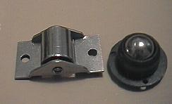
Here is a view of the altitude axis and a view of the
azimuth of a typical roller drive with small palm sized gear reducer in front
of the stepper motor. Notice how the
azimuth axis is slightly tipped and the end of the drive shaft is conical.
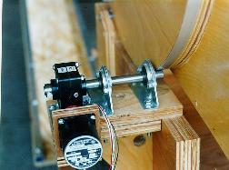
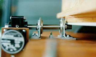
For more, see the following websites:
Make your own drive gear: http://easyweb.easynet.co.uk/~chrish/worms.htm
And Eric Greene's cast your own drive gear: http://ngc1514.com/Computer/azimuth.html
Tom Krajci's making your own drive gear: http://ngc1514.com/Computer/tom.html
Rex Kindall's gear made from side by side nylon
threaded rods http://www.geocities.com/kindellism/Nylon_Worm_Gears.html
Jan VanGestel’s threaded rod driven 20 inch http://home.wanadoo.nl/jhm.vangastel/Astronomy/50cmscope/computerized.htm
Gary Wolanski's homemade aluminum gears http://www3.telus.net/gwolanski/Gearcutter.html
Lew Cook's unusual declination drive http://www.geocities.com/lcoo/eng29.htm
Mark Rice's homemade threaded rod drive http://homepage.ntlworld.com/ecliptic/worm.htm
Moldable bearings: http://www.moglice.com/index.html
Don Clement's cable drive http://mysite.verizon.net/res0owmd/id4.html
Don Cement's flexible threaded rod drive: http://mysite.verizon.net/res0owmd/id5.html
Titolo Pagina toothed belt drive http://web.tiscali.it/robertopipitone/page18.html
Charlie Stark's friction drive system with manual push
option using a DobDriverII http://www.astrosurf.com/altaz/ddalter_e.htm
Vincent Steinmetz’s study of
belt drives http://xmcvs.free.fr/ep/index.htm
You can mold teeth into the rim of a circle or arc, then press a threaded rod against the teeth for a smooth
drive system. Because many teeth touch at any one time, errors in threads and
teeth are averaged out, and there is no backlash. In the late 1970's I used
such a drive on a 10 inch fork mounted reflector to take long exposure cold
camera images on film. See Sky and Telescope April 1979 for my article.
I used wood putty to form the threaded impression,
dunking the threaded rod in WD40 for a release agent. I worked the threaded rod
around the rim. In use, grease helped reduce the drive friction. This idea came
from Roger Tuthill and earlier amateurs who experimented with nylon and other
materials. In Roger's case, he created a long split nut that was clamped around
the threaded rod, linearly pulling a tape that was wrapped around a drum that
was attached to the shaft. Here’s the 10
inch in action:
.
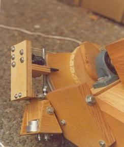
Making Your Own Drive Gears by Tom
Krajci
In the last couple weeks I've been having some success
with an inexpensive drive idea...for those that want motorized tracking, but
don't want to shell out the $$$ for a Byers gear set, and don't mind
tinkering/building.
- Make a sector of plywood or plastic (cut it with a
router or jigsaw)
- Wrap some nylon threaded rod around the sector (can
be pre-bent to the sector radius in boiling water)
- Apply JB weld in a fillet on both sides of the nylon
threaded rod, let dry
- Remove threaded rod (nylon won't stick to the JB
Weld very strongly, even without a release agent)
- Trim/clean up the rough edges
Presto...a large sector drive! How big?
Mine is about 11 inch radius. You
can make yours larger if you want. (This
may not work very well on smaller radii unless you use finer/thinner threaded
rod.) I used 5/16 -18 threaded rod. Use the same diameter/pitch threaded rod
(nylon, brass, steel?) for the worm.
Attach to a stepper or synchronous motor.
Wanna make a continuous worm? Do it in two steps. First mold a partial section on the
disk. Then, the second molding step is
the rest of the disk...with the ends of the threaded rod firmly meshed into the
ends of the first molded worm gear section.
Can this really work? It did for
me...on the first try...a seamless/continuous 21 inch diameter worm gear with
1187 teeth.
I've been able to find nylon threaded rod in six foot
lengths. That can make a pretty big
worm! ;-)
With a big enough worm you can use a "direct
drive" system....which means low/zero backlash,
and only one source of periodic error (one worm meshing with one worm gear, no
reduction gear train). One motor, one worm, one big worm gear. Choose whatever worm gear size and threaded
rod pitch will meet
your design needs.
If done carefully, this is easily good enough for wide
angle imaging. I have not tested it for
longer focal length photography possibilities, but periodic error in my first
version is smooth, not jerky. I bet an
autoguider could handle it better than many mass produced, inexpensive drive
units!
Currently I'm using these gears to drive my sixteen
inch, f/6 dobsonian. With surplus steppers rated at 6 volts, driven at 24
volts, using a small flywheel to smooth rotor resonance problems (lower
fundamental resonance freq of the rotor), and some series resistors for current
limiting at low step rates...I can halfstep slew this large telescope at 2.75-3
degrees per second. Duck!
PS. Is this an
original idea? Nope. See Sky & Tel ATM articles from 1974 and
Mel's article from April 1979. The
difference is that nylon threaded rod is now easily available.
ALT/AZ Conversion Lessons, by Chuck Shaw
The following paragraphs address the things I had to
consider and work out the details for in changing the drive system of my
14.5"f/5 Newtonian from a Dob on an Equatorial
Platform to a computer controlled Alt/Az/FR system. The intent of this article
is to add to the experience base on this type project for use by other ATM’ers.
All the basic design plans and software used were
based on the superb design and software by Mel Bartels
(http://zebu.uoregon.edu/~mbartels/altaz/altaz.html). A significant amount of
time was spent picking Mel’s brains, and also another "hero" of the
ATM world, Andy Saulietis, for his design thoughts, the use of his machine
shop, and the Field Rotator hardware design and fabrication support
(ISS@pvtnetworks.net). My deepest thanks to both these guys for the patience
and help and generous support provided!!!
In retrospect, the project was more involved than I
thought it would be when I started. Certainly not unacceptably more involved,
but its not just a long weekend’s worth of tinkering in the garage either. The
biggest thing that soaked up time was the machine shop work for the gear
mounting hubs and pressure-plates and the drive rollers and the field rotation
system. The modifications to the rocker box actually went quickly, but the
build up of the drive system components was done slowly since there was a lot
of "design thinking" along the way. The electrical subsystem was
quite straight-forward. I did not etch a circuit board (even though there are
links to the design on Mel’s Homepage) since I am comfortable with doing point
to point wiring. If several folks are building systems at the same time, using
etched boards would probably be a smart move if tasks are divided up.... The
"tuning" of the system was quite involved (as most hardware/software
integration activities turns out to be!). It was also one of the most
satisfying stages of the project. The first step was just to learn the ins and
outs of the software and the "theory" behind how Mel designed things.
This was also quite enjoyable for me to learn about (and undoubtedly a GREAT
relief to Mel when I finished so the flood of questions would slow down!!) I
think learning about new things is a key to satisfaction as an ATM’er.....
Certainly not REQUIRED, but I think it is a fun part of the overall experience.
This learning about things and the act of passing it on to others is really
what prompted me to write this info down.
Bottom line, the system is simply amazing! It was
CERTAINLY more than worth the effort to change the drive system to this
Alt/Az/FR configuration for the uses I want for it. However, as with most
things, it takes USING it to make using it second nature.
This was a question that my wife often wanted to ask
but was far too tactful to actually voice. My motivation for doing the
conversion was to minimize the polar alignment time required for imaging with
my ccd camera (since imaging with unguided tracking
requires much more precise tracking than visual observing). I used to spend an
hour or so tweaking the polar alignment of my equitorial platform to get
consistant 30 second unguided tracking imaging. Now, in less than 10 minutes I
have a system that provides consistant 1 minute unguided tracking and I have
gone as long as 4 minutes unguided!!! That allows me to set up and perform some
imaging on week nights and still get done in time to get to work the next
day!!!
Besides the more obvious enjoyment of simply playing
with astrophotography, the need to do imaging stems from the fact my sky at
home in suburban
Now, on to how all this came about:
There is a management approach that lays out all the
"stuff" that needs to be done for a project and then draws what is
referred to as the "critical path" through all the individual pieces.
(I suspect this approach was originally developed, after the fact, by the guy
that first built a "big" boat in his basement.......) However it
originated, it is an EXCELLENT thing to do! When I went through it, I found
that I needed to do the things that would change the balance and dimensions of
the OTA first, then let that define the size of the rockerbox, which then
defined the groundboard size and configuration. When I did this, I came up with
the following order of doing things:
UPDATE THE OTA (Optical Tube Assembly)
"SUB-SYSTEM":
1. Update Sec Cage
ü Upgrade Focuser to a Ball Bearing model to carry the
extra weight of slide/ccd camera
ü Build a Field Rotation System to rotate the
focuser/camera
2. Shorten Truss Tube assembly (to move the focus back
out by the amount the focuser was moved in the sec cage due to the Field
Rotation gear diameter needing more "clearance")
ü Shorten tubes and modify attach plates to shorten
overall length of upper truss assembly
ü Shorten Elastic straps on lower end of Light Sock (due
to shorter OTA)
3. Rebalance OTA for CCD Ops: (Slide/CCD Camera/wires/
filter wheel/finder/Telrad)
ü Radial (Y axis) Balance 1st
ü THEN Longitudinal (X axis) Balance
UPDATE THE ROCKER BOX "SUB-SYSTEM":
1. Build/Attach Altitude Bearing Trunions to OTA
ü Build Altitude Bearing Trunions and cover with metal
on circumference.
ü Attach Altitude Bearing Trunions to
2. Modify Rockerbox sides to accomodate larger
diameter Altitude Bearing Trunions
ü Measure required height of pivot point to clear the
Encoder and wires on the Az Bearing Stud. Add about an inch to be
conservative......
ü Scribe sides and cut circles for altitude bearings.
Put center of vertical optical axis directly above az
axis. (remember the clearance is less when the OTA is
non-vertical as the bottom edge swings by!!)
ü Mount 3 idler bearings to carry altitude trunions (4th
support point is the altitude drive roller)
ü Fabricate Ring Gear Hub/Clutch System for
worm&ring Byers Gear (Same for Az system)
ü Fabricate Worm Mount: (same for Az System)
ü Mount Motor/Worm Mounting Plate to Aluminum Angle
Bracket (same for Az system)
ü Fabricate and Mount "Tailstock" for Worm
Gear to stabilize worm (same for Az system)
ü Fabricate
ü Mount Alt Drive Roller Assembly to side of Rockerbox
4. Modify Rockerbox for Az
Drive Roller system:
Build new bottom to Rockerbox:
ü Two 24" dia 3/4" plywood disks glued
together.
ü 10ga galvanized steel sheet 24" dia circle
(Jigsaw metal blade, lots of cutting oil, and go slow)
5. Add mounting shelves to sit Laptop on (attach on
front of rockerbox and make wide enough to sit laptop on sideways) and for
eyepieces (attach on observer side of rockerbox)
BUILD A NEW GROUND BOARD "SUB-SYSTEM":
1. Fabricate
ü Drive hub, motor mounting, and gear mountings all the
same as for Alt Drive
ü Fabricate a Tapered Az Drive Roller
ü Graphically lay out angle required for taper on end of
Drive Roller
2. Fabricate Azimuth Axis "axle"
ü Use a 3/4" Pipe Floor Flange and 3/4" Pipe
Nipple and coupling and Tapered Roller Bearing (1" ID)
ü Length of pipe nipple: Height of Drive Roller Plus
thickness of Rocker box base Plus cap thickness
3. Fabricate Idler Bearings and Brackets:
ü Two Bearings, each 120 degrees apart from Az Drive
Roller
ü Fabricate "jacks" to elevate the rockerbox
up off of the idlers and Az drive roller when being
transported.
ü Properly locate, align, and mount the components on
the ground board.
BUILD THE DRIVE ELECTRONICS "SUB-SYSTEM":
1. Build up motor drive circuit section for Alt and Az Drive Motors
2. Build up motor drive circuit section for FR Motor
(SAA1042)
3. Build wiring harnesses for Az
and Alt Drive Motors for rockerbox.
4. Build wiring harness for OTA: (FR Motor, Dew
Heaters)
UPGRADE THE DRIVE ELECTRONICS:
(OK to delay this till system is up and running
without it)
1. Build MG III Circuit
2.
3. Build cables for serial port and two encoders.
Design Details and Fabrication Notes:
Once the overall "Plan" was
developed, the devil was in the details.....
1. OTA DESIGN AND FABRICATION:
Balance Weight Attach/Adjust System (X and Z axis, no
need for Y axis).
The coordinate system I refer to on the scope has the
"X" axis along the long axis of the OTA. The "Y" axis is
side to side through the altitude axis. the and
"Z" axis is vertical when the tube is lowered parallel to the ground.
Having the system on ball bearings means it MUST be
able to be balanced very accurately to avoid slippage on the drive rollers.
Since my scope is a truss tube design. I elected to have a #2.5 balance weight
on a clamp that I can slide along the tubes. With a lightweight eyepiece, the
weight must be all the way forward towards the secondary cage to balance in the
"X" axis. Heavier eyepieces require sliding the eyepiece back towards
the Primary. With my CCD camera and Eyepiece slide mounted, the weight gets
removed.
The scope also needs to be balanced in the
"Z" axis since as the elevation changes the moments on either side of
the altitude axis change. Again, the same weight clamp for the "X"
axis will work, just move it to a different tube to change its Z position.
Unlike for a German Equatorial Mount, there is no need
to balance the OTA (and rockerbox) in the "Y" axis to a high degree
of balance as long as the ground board is "reasonably" level.
Critical Path to find Balance Point:
The need to add a Field Rotation System for longer
image tracking times in any part of the sky added weight to the secondary cage.
Since I refuse to add "large" counterweights (been there, done that,
my back still hurts from lugging extra weights around!!) I needed to finish the
secondary cage first to be able to rebalance the OTA. The configuration change
of adding the FR system also required moving the focuser further away from the
Primary to allow room for the 8" diameter gear that the focuser mounts on
to be mounted in the secondary cage. To keep the focal plane from being pulled
into the focuser too much, that required shortening the truss tubes (which helped
correct the heavier secondary cage, but not enough by itself). Once the OTA
balance point was found (default state was a lightweight eyepiece and a
"small" counterweight all the way forward), then the rockerbox sides
could be marked and cut to match the altitude trunion circles and to allow for
clearance under the OTA as it swings up towards the zenith. The clearance needs
to accommodate the wires going to the AZ motor as well as the Az encoder. Keep this as small as practical, but I would
never end up with less than 1" of margin since it seems there is always
something else that ends up getting added to eat up that clearance... Also
remember that the clearance is the smallest as the edge of the scope swings
past the azimuth axle, not when the scope is vertical!
An important requirement to meet for the system to be
able to provide accurate tracking is to have the X, Y, and Z axes of the scope
all orthogonal, and their relationship well defined (and aligned) with respect
to the Altitude and Azimuth Axes of the rockerbox. With a truss tube system
small differences in Reassembly can make enough of a difference to change
collimation and small axis shifts with respect to each other. To compound this,
my scope is actually a DOUBLE truss configuration (a true serurrier truss) to
allow the balance point to be near the center along the X-axis but not require
a physically large mirror box (i.e. The altitude trunions are attached to a
"ring" that has truss tubes going aft to the mirror box, and also
forward to the secondary cage.
To make VERY sure that the system is able to be
reassembled to exactly the same configuration as far as spacing between
components, a number of brass screws were inserted in the mirror box, center
ring, and secondary cage and then their heads cut off, leaving small brass pins
in the wood. Their exact locations were defined with an aluminum template made
from a 1/2" wide, 1/16" thick aluminum bar long enough to reach
between the components (secondary cage, center altitude axis ring, and Primary
Mirror cell). Once the scope is assembled, the template allows small
adjustments in the truss tube attachment clamps to "tweak" the
configuration. The result is virtually no re-collimation is needed when the
scope is reassembled. And the mechanical alignment of the OTA, being very
repeatable, assures the Alt and Az axes relationship
for the rockerbox keep their relationship to the OTA axes. This use of a
template requires a very slight bit more "hassle" during assembly,
but in reality the extra activity to use it is in the noise, and the precision
it provides more than compensates. More "stock" truss tube dobs might
be able to get away without a template since precision cut tubes inserted into
precision located sockets (with bottoms) actually form their own templates.
The scope.exe software needs to be told when the scope
is either perpendicular or parallel to the azimuth axis as part of the
initialization process. I think the simplest way to do this is to have the
scope aimed vertically (parallel to the azimuth axis actually, since the
platform does not have to be level). To make sure this is so, I have an
adjustable hard stop to be able to rotate the scope up and against the stop.
The adjustable hard stop is mounted on the inside of the front panel of the
rockerbox. The spin align technique allows me to measure this position to a
very high (arc second) accuracy and once adjusted it is very repeatable.
Spin Alignment Technique…(Optical and
Mechanical Axis alignment)
As mentioned previously, the OTA and the Alt/Az axes
need to be aligned very carefully. There is actually a very simple and
straightforward technique for doing this alignment that Andy Saulietis showed
me. With the scope aimed vertically (not necessarily vertical as with using a
bubble level, but instead make it parallel to the Azimuth axis) with the OTA
against the hard stop and secured there with a bunjee cord, suspend a video
camera above the scope, looking down into the OTA. Position it just off set
from the secondary mirror to look past it down towards the Primary. Set the
focus at infinity (and turn off autofocus). Take the camera video feed and send
it to a monitor/TV convenient to the scope. At the eyepiece, you need to have a
pinhole light source and have it located at the focal plane. An easy way to do
this is to cut the end off of a plastic 35mm film can and punch a small hole
(less than 1/16" dia and as round as possible) in the lid. Re-install the
lid on the film can and tape it to a small flashlight (the lid towards the
flashlight). Then just insert the film can into the focuser and rack the
focuser in/out till the lid is at the focal plane. All of this will result in a
collimated light beam being shone at the camcorder. To initially get the system
looking at the light dot, use low power zoom. Once you have the light dot in
the FOV, use as much magnification as possible (I used a 200mm telephoto lens
afocally projected onto my camcorder objective lens with the camcorder set at a
zoom of 6x).
As the scope is rotated in Azimuth, the small dot of
light will describe a circle on the TV screen. Pick 4 "cardinal"
points with respect to the ground board. to use as
reference (i.e. call them N, S, E, and W, or 0, 90, 180,and 270). The idea is
that you will adjust one of the altitude sectors fore and aft along the
"X" axis of the OTA, then rotate the rockerbox to see if that made
the circle smaller. Ultimately it will collapse into a line from a circle when
the side to side tilt of the OTA’s "X" axis is finally made
orthogonal to the Altitude axis (and perpendicular to the Azimuth axis). The
next step is to adjust the altitude hard stop on the front of the rockerbox
that limits the OTA altitude to 90 degrees. Adjust it in the same manner as for
the altitude sector adjustment till the motion due to the tube not being
parallel to the azimuth axis in altitude collapses to nothing.
By going back and iterating the adjustments once or
twice, and by using as much magnification as possible, you will end up with the
dot probably describing a small figure 8. This is due to any small astigmatism
in the metal plate on the bottom of the rocker box that forms the bearing
surface and any "noise" in the bearings or bearing surface. The
actual angular errors can be measured quite accurately, especially if you use
high magnification. The size of the dot (actually the subtended angle) can be
calculated by measuring the actual size of the pinhole in the film can lid and
using the formula: (P/F)x(206.265)=D where P is the
dia of the pin hole, F=focal length of the Primary Mirror, D=arc sec that the
Dot image subtends. Then, the distance the dot wanders from the
"center" of the figure it describes can be measured in terms of dot
diameters on the TV screen, and then multiplied by the calculated angular size
of the dot.
Is FR needed or not? For visual use only, field
de-rotation is certainly not required. If you limit your photography to looking
east or west field rotation is very small and it is not required. Other areas
of the sky have varying degrees of field rotation and the sensitivity to it is
a function of the exposure lengths. An article in Sky and Telescope (Sept 1992,
page 312) shows you how to calculate how much field rotation you will
experience for different places in the sky. Another way to calculate it is the
following formula: FRR=WcosZcosL/cosA where FRR is the field rotation rate,
W=earth rate (15.041 deg/hr=72.9 urad/sec), Z=object
azimuth, L=observer latitude, and A=object altitude. CCD photography allows you
to track and stack images. As long as the individual images do not show
trailing due to FR, there are software packages such as "SuperFix"
and "Mira" that allow images to be derotated before being stacked.
Richard Berry has developed a very powerful derotation scheme that is quite
easy to use for Cookbook images (it is an updated version of his quite powerful
track and stack software MULTI245). So, FR can be done in software or in
hardware. If you do intend to do a lot of astrophotography or longer duration
film astrophotos, I recommend building in the system mechanically since the
software derotation cannot correct individual long exposure images that get
smeared by field rotation which is, of course, worse for long film shots than
for the generally shorter ccd exposures. If you cannot
decide if you need a mechanical FR system , remember
that adding a mechanical FR system later will add weight to the secondary cage.
You will need to either allow for shifting the altitude trunions forward to
re-balance the scope (i.e. you should make the clearance under the scope bigger
than what is needed initially to allow for this shift aft later) or commit to
adding counterweights to avoid moving the altitude sectors.
2. ROCKERBOX DESIGN CONSIDERATIONS:
Azimuth and Altitude Trunions and Bearings
Sizes:
The larger the diameter of the trunions, both Az and alt, the better the drive ratios available and, in my
opinion, the better the stability of the scope. I use 24" diameter
trunions on my 14.5"f/5 Newtonian for both Altitude and Azimuth bearings.
The Altitude trunions are 180 degree sectors (360 degree circles cut in two).
Andy Saulietis likes to have two alt drive rollers (one for each alt trunion).
To keep them running perfectly together, he connects them with a common drive
shaft. This works very well, but slightly complicates the disassembly of the
rocker box if that is desired. I have a requirement for my rockerbox to be able
to be disassembled into small components so I can fit everything into the back
of my standard size Plymouth Voyager without removing the rear seat, only
folding it down, so I opted not to use the dual drive rollers.
Rockerbox
Disassembly requirements (single or double drive roller consideration):
Andy advocates two drive rollers to avoid any
"torque" put into the OTA from only driving one roller under one
altitude trunion. He is convinced that the torque, while small, is still enough
to detract from unguided astrophotography. When Andy is convinced about something,
its usually the way it really is.... To drive one
roller under each altitude trunion and drive them perfectly together, you need
to connect the two rollers with a common drive shaft. This means the altitude
trunions have to be big enough to allow this drive roller connection linkage to
clear the OTA. This can result in pretty large trunions! I wanted my rockerbox
to be able to be disassembled to take up less room in the car when being
transported. To do this the mechanical system to mount the rollers has to
either be one piece to maintain structural alignment between the rollers, or be
a bit more complicated to be able to be disassembled with the rockerbox. I
elected to initially build my system with only one roller and I have to admit,
I have not seen any tracking errors that I would attribute to torque from only
driving one altitude trunion. Thats not to says its
not there, but I cannot see it, even in my CB245 ccd images with up to 4 minute
unguided tracking. So, my suggestion is to initially build with only one drive
roller under one trunion and see if that works for you. You can always build
larger trunions later and a second drive roller, but I am betting you will not
have a problem only using one. I did hedge my bets against slippage though. I
have a turnbuckle attached from an axle bolt that is along the altitude axis.
It extends down to the rockerbox. I tighten it a bit when there is a breeze
blowing or the OTA balance is not perfect in the altitude axis. Another
alternative in order to drive both sectors is to use two motors and drive
rollers, one for each trunion. The "base" of the transistors for the
corresponding (i.e. same) motor windings for each of the two motors should get
tied together so the same pulse from the computer to send current to one motor
goes to the other motor at the same time. I have used this for equatorial
platform drives that have two drive rollers and it works quite well. However,
till I see otherwise, driving a single drive roller under only one of the two
altitude trunions seems to work well.
Materials:
Wooden disks, carefully cut with a router, are plenty
accurate for the Altitude Trunions. Mine are two layers of 3/4" plywood
glued together. They need to be faced with metal to provide a more durable and
uniform surface for the drive roller and idlers bearings. Aluminum works fine,
but a much better alternative is 22 gage stainless steel.
Get the metal yard to cut it into the right width strips and a bit longer than
the circumference. The Azimuth bearing surface on the bottomm of the rockerbox
can be aluminum or stainless or galvanized steel. I chose 10 ga galvanized
steel since it is very flat, and very cheap. Aluminum can wear too fast if you
are using steel idler bearings, and stainless can get expensive in addition to not
being flat if its been stored in a roll.
Altitude
Sector Position adjustments:
One of the best suggestions I was given was from Andy
Saulietis. He said to make one Altitude trunion permanently attached, and the
other be "adjustable" in both the X axis
(along the OTA’s optical axis) and the Z axis (top to bottom of the OTA when
the OTA is parallel to the ground). The adjustment in the Z axis is easy to do
just by loosening the bolts attaching the trunion. But the act of loosening
them will allow the tube to slip in position (assuming the holes in the sector
are oversize and covered with larger fender washers). To manage this slippage,
attach a hangar bolt into the trunion so that it is parallel with the long axis
of the OTA and going forward towards the secondary mirror end of the tube. Also
attach a metal plate or block attached to the OTA that the hangar bolt goes
thru with a nut on both sides of the plate/block. With the tube vertical, and
the attach bolts for the trunion loosened, the weight
of the tube is carried by the hangar bolt attached to the plate/block on the
OTA. Very precise adjustments of the position of the trunion can be done using
his scheme when performing the "spin align" technique for making sure
the optical and mechanical axes are properly aligned.
If the scope is to be used for astrophotography,
another adjustment that should be performed during the building process is to
shim the attachment of the altitude trunions to the OTA so that they describe
two parallel planes on either side of the OTA. All of this assumes that the
rockerbox has some type of side to side restraints installed to make sure the
sides of the OTA do not interfere with the rockerbox and the trunions stay
centered on the drive and idler rollers. While not mandatory for visual work,
this shim adjustment will prevent the OTA from shifting from side to side as
the elevation changes due to the side restraints riding against the trunions
and "pushing" the scope laterally. In addition, if they are not
parallel the trunions may bind at one point, and be too free at another. So,
shim the trunions as well as you can, and then install two restraints (teflon blocks or even better, two small roller bearings on
angle brackets) on one side so they bear against the outside surface of the
trunion. On the other side of the rockerbox, install one bearing, but this time
make it spring loaded so that the plane that the OTA will describe in elevation
(Altitude) will be defined by the one trunion’s side riding against the two
fixed side restraints. A small bit of extra trouble to
install, but well worth the extra effort, especially if the scope may
occasionally not be sitting on level ground.
Azimuth
"Axle" and "Coupling Nut"
Another great suggestion from Andy Saulietis was to
use a "hollow" azimuth axle to be able to feed wires through it. Make
it from a 3/4 inch (ID) pipe nipple screwed into a floor flange. A tapered
roller bearing is mounted into the bottom of the rockerbox ("V" shape
of the bearing down). The ID of the bearing should be 1". The unmachined
pipe OD is slightly more than 1" so that when turned down in a lathe it
fits with very little play. Then turn around the pipe/flange in the lathe and
face the bottom of the flange to end up with a flange surface that is perfectly
orthogonal to the pipe side surfaces. Use a "coupling" for the
"nut" on top to be able to screw down against the top of the tapered
roller bearing to increase the effective "weight" of the scope to
eliminate any az roller slippage (no problem for heavy
scope, but lighter scopes can slip). The coupling will also allow the wires to
pass through it. Use an aluminum electrical conduit coupling and you can more
easily cut it in half to make it shorter for better clearance from the bottom
of the rockerbox..
Use of Azimuth
roller under rockerbox vs "pinched roller" system
Mel Bartels’ basic design calls for a
"tapered" roller under the rockerbox’s base. This allows the weight
of the scope to be used to help eliminate slippage. Andy uses, in one of his
designs, flat rollers on the bottom of the rockerbox, and a machined surface on
the top and outside edges of a ring of metal that these bearings ride on. The
azimuth axle and bearing keep the rockerbox and its bearings riding on the
metal ring base.. The drive motor and roller are
mounted on the front of the rockerbox so that the drive roller is against the
machined outside edge of the ring. To engage the drive, the mounting plate and
bearing for the drive roller are pulled back against the outside edge of the
ring. This design trades off machining a tapered roller and then locating it
along the radius to the center of the azimuth bearing surface very accurately
against machining the base ring, but only having to deal with cylindrical
surfaces. Since machining a taper is not that difficult, and Mel’s system more
effectively uses the weight of the scope to avoid slippage rather than just
mechanical pressure, I opted for Mel’s design. While fine for visual work,
belts or chain type systems simply have too much play in them for very accurate
unguided astrophotography (my goal with this system) and tape/cable drives have
to be rewound (which Murphy’s Law requires to typically happen 1/2 way thru an
astrophotography exposure!)
Azimuth
idler bearings:
I used two roller bearings as idler bearings under the
azimuth base plate surface of the rockerbox. The two idlers and the az drive roller are set 120 degrees apart and are adjusted
so that they are all at the same height. The idlers run on an axle bolt running
between two pieces of aluminum angle. Make sure the axle bolt is aimed very
precisely at the azimuth axis to avoid "skidding" of the idler
bearing on the rockerbox bearing surface. My two idlers are at a different
radius from the center of the az axis so they do not
run along the same track on the surface of the rockerbox bottom surface as the
drive roller uses. This is to insure any damage or wear on the surface of the
rockerbox base caused by the very hard idler bearing outer race will not affect
the machined drive roller.
Alt Bearing
Height (inset vs surface mount):
I chose to "inset" the drive roller and the
idlers for the altitude trunions into the sides of the rockerbox to allow a
smaller clearance between the altitude trunions and the radius I cut out of the
sides of the rockerbox, and to simplify mounting the idlers (i.e.only the upper
limb of the idler bearings and the altitude drive roller are
"inside/above" the scribed altitude trunion circle). They ride on
axles between plates thru bolted through the rockerbox sides. This was not only
for esthetics, but if the drive system fails, I still have the old teflon pads
from pre-drive system days and they can slip in on thin shims to lift the alt
trunions off of the drive roller and idlers to return the scope to its original
"dob" feel.....
Alt Bearing
"Spread" under Alt trunions:
For a conventional dob,
spreading the alt teflon pads further apart increases the alt axis
"friction" and moving them closer decreases the force needed to move
in altitude. With roller bearings, the force is effectively the same no matter
what the "spread". So, move them as far apart as possible to increase
stability. Build the mounting system for the altitude drive roller first, and
mount that as far out as possible. Let that define where the idler that is on
the opposite side of the rockerbox is mounted. The other two idlers are mounted
to give the largest "spread" under each altitude trunion as possible.
Gearboxes vs
Worm Drives vs Drive Rollers vs Drive Belts (accuracy reqmt’s vs simplicity):
This area requires a bit of thinking on the builder’s
part. "Good" gearboxes are expensive and still seem to have periodic
errors (and not always smooth ones either!). However, they are a simple
solution. Worm drives are less expensive, but you have to fabricate a hub for
the gear, and a mounting system for the worm. Someone without access to a lathe
would have to get the work done by a machine shop, which could cost more than
using gearboxes.... Also, getting the worm and gear mesh set up perfectly to
minimize periodic error sometimes can really be a pain. If you go this way, be
sure to get the bushing blocks for the worms along with the worms. The best
worm config is one that has the worm in the middle of a shaft, so that bearings
can be used on BOTH ends of the worm. The shaft needs to be long enough to get
the bearings far enough away from the gear to clear the gear..... If you use a
bushing material, the clearances must be no more than about 0.00075 inch. An alternative
if the worm has a shaft only on one end is to fabricate a "tailstock"
from a brass machine screw ground to a point and mounted in a small bracket so
that it can be inserted into the center ground hole in the end of the worm.
This will steady the worm on that end. The motor will probably have good
bearings and a good coupling between the worm and motor will provide support on
that end. Watch out for couplings with too much clearance for the shafts or for
"flexible" couplings. This will allow the worm to move and will
induce periodic error that is not entirely repeatable (maybe this should be
called random error rather than periodic?). Again, this is primarily a caution
for astrophotography.
A system without gears avoids many of the problems
with the previous two systems. An aluminum disk with a hub that is set-screwed
to a shaft and a bronze or brass roller pressed hard against it should have no
periodic errors. There must be a fair amount of pressure to eliminate slippage,
so all shafts need to run in ball bearings to control rolling friction. Even
well lubricated bushings will have too much friction when the drive roller is
pressed hard against the disk. This is also a simple system to clutch. Just a
quick release cam pushing against one of the bearing blocks supporting the
drive roller will decouple the system. Again, you need access to a machine shop
to fabricate the disk/hubs, but this should be much cheaper than the hubs and
pressure-plates for the worm gear systems. With all of this going for it, what
is the down side?? There are only two that are of consequence. The first is the
susceptibility of the system to contamination changing the drive rates. The
rollers need to be kept as clean as possible. Initially, its
a good idea to use something like valve grinding compound to "lap"
the roller surfaces into each other, but when accuracy is needed, the surfaces
need to be kept clean and dry. The second concern is inadvertant
"skidding" of the surfaces against each other. This is different than
slippage. Skidding would happen if the OTA was moved with the system "in
gear". The problem is a small flat spot gets easily made on the smaller
diameter drive roller. If that roller is brass or bronze, it will happen much
easier than if steel. However, the steel roller will be more susceptible to
slippage. This system is probably the best one overall to use if you take care
to avoid the skidding and contamination problems.
The drive belt system is probably the easiest system
to build. For a purely visual use system, it is also probably more than
adequate for a light weight OTA. However, for photographic tracking accuracy, a
drive belt is simply not accurate enough. This is true whether the belt is
something like a cogged belt or a chain drive. A continuous steel tape might be
the exception to this, but the joint in the band would have to be VERY good....
The same concerns for contamination and slippage would be present, but the
skidding problem would probably not be of concern.
With all these options, the biggest factors for the
builder will be what level of access to a machine shop the builder has and how
accurate of a system you need (visual is much more forgiving than unguided
astrophotography). I built worm drive systems for my Alt and Az
drives, using surplus 4" Byers Gears originally made for Byers CamTrack
systems. They were advertised to have 4-7 arc/sec of periodic error. In reality
the final configuration had closer to 40 arcsec of PE. (due
to the gear and worm themselves, plus bearing slop and any slight misalignment
of the worm mesh). When divided by my 12:1 final ratio for my drive roller to
sectors, this dropped to about 3-4 arc sec. The scope.exe software PE
correction PEC) routine was able to reduce this to an undetectable amount of PE
at the Altitude and Azimuth Axes. The gears also required machine shop time to
build hubs and pressure plates to capture the gears and form a
"clutch" system. The configuration works extremely well, but in
retrospect I think I will go with drive roller reduction for any future systems
due to its simplicity, lack of PE, and much less cost.
Gear
Diameter considerations:
The gears for the worm gears for my system are
slightly larger than 4" dia. For the Alt drive roller, this posed no
problem in mounting the worm and stepper motor just below the gear. A block of
several thicknesses of plywood was built with the bottom piece of plywood
forming a "shelf" that the motor and worm bearing bracket could mount
on. The same approach as used for the Azimuth drive, with the thickness of the
ground board making up two of the thicknesses of the block. The motor and worm
were mounted below the gear to keep the motor low. In retrospect, the motor and
worm could have been mounted to touch the gear at the
Drive System
Disengage Requirements (to clutch or not to clutch?):
Normally, the software (scope.exe) keeps track of
where the mount is aimed by keeping track of the commanded steps sent to the
stepper motors, and via occasional positional updates on targets with known
positions. However, because of the very high gearing ratio I am using, which
makes slews to objects rather "stately" in their speed (and my
general impatience in getting the scope slewed to the next object) I elected to
add the optical encoders to both Alt and Az systems and clutches on the systems
to be able to disengage and move the scope manually and then re-engage the
motors. The Printed Circuit Board for the MicroGuider III system from
To take advantage of the encoders
ability to update the computer’s knowledge of where the scope is aimed so you
can manually move the scope, you have to also have some sort of clutch system
to disengage and then re-engage the motors. With an all drive roller reduction,
having the motor and 1/4" shaft on a moving carriage with a screw
adjustment to press the small shaft against the larger disk (which is on the
shaft that has the drive roller on the other end) works fine. The shaft with
the drive roller and large disk should run in two pillow blocks, with collars
to react lateral loads. An over center lever (like on a bicycle front axle) is
faster than the screw adjustment for the motor carriage. The small shaft needs
to be of something rather soft, like brass, and be suspended between two
bearings (do NOT just use the motor’s bearing, the forces needed to keep things
from slipping are too large!).
For gearbox systems, they can be clutched to the drive
shaft holding the drive roller with a simple collar that slips over both the
drive roller and the gearbox output shaft. The collar needs to have a strong
set screw in one end and a thumbscrew in the other end to be loosened (as the
clutch). If the collar also functions as a size adapter (different size gearbox
output shaft size than drive roller shaft) put the thumbscrew in the end with
the larger shaft for better mechanical advantage and less torque required to tighten the thumbscrew. Minimize the "play" in
the collar since that will be a source of PE.
Worm gear drive systems have a different challenge.
The motor and worm need to be carefully adjusted so the mesh of the worm is
correct (to avoid excessive backlash and periodic error). This means, after all
those adjustments, you do NOT want to disengage the worm from the gear as the
clutch system.
I considered not using any clutching system, and only
doing my slews with the drive motors. I also considered no clutches and just
moving the scope manually and allowing the sectors to "skid",
counting on the encoders to detect any slippage..
Since I wanted to minimize slippage for astrophotography, anything I did to
minimize slippage would work against this way to manually reposition. In
addition, I was a bit concerned about damaging the drive roller surface. Even a
very small flat spot would show up in an unguided ccd
image. So, the challenge was to come up with a very simple clutch system.
The approach I took is similar to the traditional
mounting scheme for the gear. Namely, to capture the gear between two
"hubs" that get pressed together. The hubs
are machined to fit the recesses in the inner flange/hole of the gear. One hub
is set screwed to the drive shaft going to the drive roller. The other hub’s center
hole is slightly oversize and is free to move up against the gear, or to move
away to "declutch" the system. The free (outer) hub then has a small
disk slipped over the drive shaft out side the hub. This disk has three machine
screws through it that press onto the outer hub. One of the machine screws
should be a thumbscrew. Then, outside the disk, is a collar that is set screwed
to the shaft to complete the assembly. To tighten the two hubs together, simply
snug up the thumbscrew. This will take up any "slack" in the stack of
components trapped between the inner hub (set screwed to the shaft) and the
collar (also set screwed to the shaft). Very little tension on the thumbscrew
is needed. The clutching action is very fast and very strong. Unlike normal worm
and gear clutches on equatorial mounts, which use a fiber washer to allow the
slippage to be modulated, this system should not use any washer nor any
lubrication between the hubs and the gear. You want it either totally engaged,
or totally free, and to be quick and simple for either operation!
Drive Roller
Ratios:
With the Byers gears giving a 359:1 gear reduction,
and Mel’s advise to have at least a 7:1 final drive roller ratio (drive roller
dia to trunion dia) , the ideal size would have been
3" dia for the drive rollers. Andy Saulietis had some bronze boat
propeller shaft material that was 2" diameter. That gave a 12:1 final
drive ratio and a 4308:1 ratio (359x12) for alt or az
to stepper motor reduction. For a 1.8 deg motor step size
(200 steps per turn), that results in approximately a 1.5 arc sec scope
movement for each full step of the motor. Slews using the motors are not
fast, but are plenty fast for me. However, I usually declutch and manually slew
when the move is very big anyway since I also added the optical encoders. There
is simply NO detectable motion in the eyepiece at ANY magnification when I am
using my Compaq 486SL25 laptop. This laptop lets me use value of about 90 for
the number of pulses sent per bios clock tick to the motors. The motion looks
just like a DC motor’s smooth motion at that rate. When I use a slower ZEOS
386-SL20 (no math co-processor), the fastest rate I can send pulses
is about 7 per bios clock tick. This is still plenty fine unless I am at
really high power, when there is a tiny oscillation seen in the eyepiece. I do
not even notice it anymore. However, I usually use the 486 to drive the scope.
I suspect a 386 with a math co-processor would not have a problem sending the
higher rate for the pulses, but the bottom line is that even a 286-16 is
probably adequate if some of the bells and whistles in the software are turned
off (using config.dat).
To get a comfortable 1 deg/sec slew rate with my gear
ratios the stepper would have to turn 2400 full steps per sec, or 4800 1/2
steps per sec. While not slow, Mel assured me the flyback diodes in his driver
circuit would allow that if the motors had enough voltage available. As it
turns out it all works just as advertised!!!!! As a matter of fact, I have test
run the motors up to 8000 1/2 steps per second!! Cylinders of the bronze shaft
material were cut and bored to fit the 3/4" steel drive shafts, and then
machined using the drive shafts themselves as mandrels. The cylindrical Alt
roller is just a touch wider than the 1.5" wide stainless bands that
surface the alt sectors, and the tapered az roller is
about 2" long with a 5 deg taper. The taper is needed so that all portions
of the drive roller turn at the right radius and do not slip. If it was a
cylinder, only one portion of the az drive roller
would roll at the right speed without slippage. Any place closer to the az axis would be rolling too fast, and if further out, too
slow. Thinking about it a different way, the circumference of the path the
inside edge of the drive roller describes is shorter than the circumference the
outside edge describes. But since the inside and outside edges rotate at the
same rate, they need to be different diameters to describe the correct length
circumferences. Looking at it a third way, the drive roller is simply a section
out of a cone that has it’s tip at the center of the
lower surface of the rockerbox bottom plate. Some simple geometry will allow
you to calculate the angle you need, based on the diameter of the roller and
how far out the roller rolls from the center of the az
axis. The Sin of this angle is the Radius of the outside (larger dia) end of
the drive roller divided by the distance this outside edge is located from the
center of the az axis.. In case you have a tough time
with doing the calculations for this, aim your Java enabled browser at the
following URL for a handy dandy calculator to do it on line:
http://www.shopstuff.com/trigcalc/trigcalc.html. In reality, it was much easier
to machine the taper on the roller to as close to the 5 deg as possible, then
measure the actual angle cut, and then, given the measured outside diameter and
the angle use the trig relationship above to determine how far to put the drive
roller outer edge away from the center of the az axis. Make sure the drive
shaft is aimed EXACTLY at the center of the az axis to avoid slippage from
skidding (slipping a long piece of the steel shafting through the pillow blocks
and lining it up with the azimuth axis makes this a simple task). The angle the
drive shaft has to make with horizontal is the same as the taper. Shine a light
opposite to the drive roller and look for light between the roller and the
bottom surface of the rockerbox to make sure the roller is mounted to the right
angle. Also make sure the entire scope is sitting on the rockerbox (or the same
weight is on the bearings) since the system will probably flex a bit and not
have the roller rolling flat against the surface when loaded down.
Worm gear
mesh adjustments
The bane of worm gears is the mesh alignment
requirements. Good alignment is required to minimize the periodic error in the
system. The worm will need to be centered on the gear side to side and along
the "axis" of the worm. Too much pressure and the friction will be
too high and the stepper motors will stall at faster slew rates (because the
available torque decreases as the motors speed up.). Too little pressure and
there is backlash in the system. Byers has used a spring loaded the mounting
for the worm against the gear for some systems. This will work fine for lighter
weight systems, but the danger is when the system is back driven (i.e. the OTA
is bumped or is out of balance) you run the risk of the worm
"skipping" out of mesh and potentially damaging the softer gear
teeth. The best way I have found is to remove the motor and hand turn the
coupling to "feel" for minimizing friction while maximizing the mesh
pressure and "eyeballing" the alignment. The good news is Mel’s
software will allow you to measure whatever Periodic error is in the system
when you are done, and then correct for it. My system uses the 4" diameter
Byers gears they made for the camtrack system. They were advertised to have
about 4 arcsec of periodic error. The azimuth gear set runs, uncorrected at
about 7 arc sec of PE, but the altitude gear set has about 10-12. This is after
the system has been through a 12:1 final drive roller reduction.....so the
actual gear errors are 12x those values!!!! However, the bottom line is the OTA
sees virtually no periodic error when tracking thanks to the PEC software
correction...... amazing!!! You also want to lubricate the worm and gear
surfaces that mesh, as well as the worm shaft in its bushing. I use fishing
reel lubricant (that contains teflon). You can get it
in most sporting goods departments. Spray on dry lube also works well and picks
up less dirt.
Voltage
requirements
This was one of the more puzzling tradeoffs during the
build process. Based on reading about steppers (probably too much reading about
steppers) I concluded that 6 volt motors run at 12 volts with dropping
resistors of a wattage and resistance the same as the windings would allow high
RPM, lots of torque, and not be in any danger of too much current in the
windings. As it turns out, the resistors are simply not required for my motors
due to Mel’s pulse width modulation scheme. By increasing MsDelayX you can
decrease the current fed to the motors. My motors are rated for 6v and 1.2
amps. That is 7.2 watts. To keep the same wattage to the motors, that means at 12v
the current needs to be limited to 0.6 amps. It was a simple matter to put an
ammeter in series with the power supply and vary MsDelayX to decrease the
current. Once again, Mel’s software is the way to go!!!!! The normal operating
current that goes to the motors while tracking is about 0.1 amp
each. High speed slews start out at about 1.0 amp each and
quickly drop to about 0.2 to 0.3 amps each during the slew. I am sure
there are motor/voltage combinations that would require the dropping resistors
in series with the windings to prevent the steppers from "buzzing" at
some particular speed range. If you run into that, its
no big deal to add the ceramic power resistors in series with the windings. But
I suggest trying it without it first.
How many
wires???
Stepper motors are a bit mystical to those not
familiar with them. Actually they are quite simple. Mel has an excellent
explanation on his website. However, they come in 4 wire, 5 wire, 6 wire and 8
wire versions..... You want to use motors that are unipolar with Mel’s driver
design, so stay away from the 4 wire models (which are bipolar). The terms
unipolar and bipolar refer to whether the motor always has the current going
through each coil in the motor always in the same direction (unipolar) or requires
that the current be reversed in the sequence on alternate pulses to each coil
(bipolar). The bipolar motors work well, but Mel’s software and circuit assumes
the motors are unipolar.
Each winding (coil) in the motor has two wires coming
from it. For 8 wire motors, both wires from all 4 coils all come out the motor.
Use an ohmmeter to find which wires go together. Since the 4 coils in a
unipolar motor are oriented opposite to each other, often the
"opposite" coils will have one end tied to each other, so now you
have 3 wires coming out for two coils, for a total of 6 wires. Use your
ohmmeter to find the three wires that are all connected to each other. The wire
coming out from the two ends of the coils that are tied to each other will have
the same resistance when measured to the other two wires. The other two wires
will have twice that much resistance when measured between the two of them (the
path goes through both coils). Five wire motors have one end of all four coils
tied together. Find the common wire (quite often the black wire) with your
ohmmeter in a similar fashion by comparing resistances and remembering that the
resistance will be twice as high if you are not going through the common wire.
Mel’s software pulses the coils in sequence. Assuming
windings A and C are opposite to each other (and tied together on one end for 6
wire motors), and B and D are tied in a similar fashion, hook up winding A to
the first output from the parallel port/hexinverter/transistor string. Then
hook up winding B. You have a 50:50 chance that the coil you are calling coil B
is actually B and not D. If the motor just buzzes and does not turn when you
try to run it, reverse these two wires. Then hook up C (you have the same 50:50
chance its actually C and not A). If the motor buzzes when started, and you
have swapped the wires to B and D, then try to swap A and C. If it still buzzes
and does not turn, go back and undo the swap you did for A and C.
For figuring out 5 or 8 wire motors, the process is
basically the same, except you do not have the luxury of a 6 wire motor having
already divided up the windings into two groups. All that is required is to
keep trying different combinations of the order the wires get hooked up in and
the fervent belief that one of them WILL work!. Build
a matrix to show the 16 different combinations, get something cold to drink,
and then go play...... You can cheat a bit by assuming the color coding of the
wires will give a clue as to which windings are opposite pairs of coils.
Direction of
rotation
This is, unfortunately, not arbitrary. However, during
the fabrication activity, it does not matter. After things are put together,
the handpaddle "up/down" PB’s can be used to see which direction
things move. I suggest that the encoders, if already built into the system, NOT
be turned on for these tests, since they can confuse things if they are
backwards. If the scope moves in the expected direction, smile and think about
being that lucky at
The field rotation motor direction is changed with the
same trick of swapping motor winding wires. The direction of rotation is, for a
Newtonian, in the same sense as you are looking at the sky. At the North
Celestial Pole, the field rotation system should be turning the focuser counter
clockwise. As you look at the southern skies, the field rotation is clockwise.
Things change somewhere in the middle (but don’t worry about where for now, the
software knows and that’s all that counts!!!)
Wheelbarrow
Handles vs built in wheels (like Mel’s original design)
Since I do not have a permanent place to leave the
scope set up, I end up rolling things into the garage when done, and then out
into the driveway or back yard to use the scope (or load things into the back
of the pickup or van to drive to a dark sky). I did not build my scope to be light, since I knew I would be primarily imaging with it and
wanted as much stability as possible. So, I have always had detachable wheel
barrow handles with pneumatic tires to roll the scope/rockerbox/platform
around. When I converted to the alt/az drive system I decided to stay with the
removable handles versus the built in wheels like Mel had in his earlier
design. In order to not damage the azimuth drive surface by bouncing the
surface against the drive roller and/or the idler bearings, I put 4 wooden
disks under the metal azimuth plate. The disks are actually "pads"
that have a carriage bolt thru them with a washer and nut capturing the pad at
the head of the carriage bolt. Then the carriage bolt goes thru a t-nut in the
top of the ground board. To relieve the weight of the rockerbox/scope from the
bearings and drive roller, I simply screw the wooden pads/carriage bolts out
till the bolts/pads start to lift the rockerbox. Works great! The wheelbarrow
handles are attached to the rockerbox with two home-made
"thumbscrews" that are "captured" on the handles and screw
into t-nuts in the rockerbox sides. They are quick to release and remove. However,
quite often when operating in the driveway where the grass cannot drag against
the wheels, I get lazy and just leave them in place.
Baseboard
size requirements
In the interest of economy I copied the clever design
that was used for the telescope called "Hercules" that I found in the
links from Mel’s website. Its worth the time to check
it out, if for nothing else than to see a really impressive scope!
Foot
locations (load paths)
In order to make sure that any flexure in the ground
board is not a problem, make very sure that the "feet" that you put
under the ground board are under the two idler bearings and under the pillow
blocks for the Azimuth roller.
Level
Even though the ground board does NOT have to be level
for the system to operate properly, having the ground board reasonably level
will help things work smoothly if the rockerbox is not well balanced. I have a
Laptop hung on the front, a reasonably heavy altitude drive roller assembly and
an eyepiece shelf on one side, and a power supply, electronics box, and MGIII
electronics box all on the other side. The result is the rockerbox is out of
balance with the "front" a bit heavy. When the system is level this
makes no difference. I attached a small bullseye level to the ground board for
an easy reference.
3. ELECTRICAL SYSTEM DESIGN CONSIDERATIONS:
Mel’s design has the option to include opto isolators
to better protect the parallel port of the controlling computer. Even though
the danger to the computer is minimal when running the motors at low voltages,
I decided to take no chances. The cost of the isolators was peanuts compared to
the cost of a repair job if any back emf, shorts, static electricity, etc, etc,
etc became a factor….(Yes, on occasion I also wear a belt AND suspenders…)
Board Layout (additional FR circuitry)
Mel’s website also points to some fine work by folks
on etched circuit boards. However, these boards do not include the field
rotation circuitry. While its true that the FR portion of the circuit could be
built on a daughterboard added to the system, I am comfortable doing point to
point wiring, even though it is not as "neat" as using a PC board, so
I elected to not go to the trouble and modest expense of etching a circuit
board. If several people were building systems together, where you could farm
out work to each other, then I think it would be a smart move to use etched
boards.
I added a small 12v fan in the electronics box to make
sure there would never be any thermal problems. I was a tiny bit concerned the
fan might cause a vibration I would see, but that is not the case.
Mounting location on Rockerbox
I decided to mount the electronics on the side of the
rockerbox, opposite to the side that the altitude drive roller and motor were
mounted on to help balance the rockerbox. I fabricated a box from a base of
½" plywood, with a top and sides from plexiglass (so the circuitry can be
seen). Mounted on the rockerbox means everything turns together, with the only
thing that needs to be tended being a single power wire leaving the telescope.
Initially I had the power supply sitting inside the rockerbox. However, the
heat it generates was a concern to me for maintaining good imaging (since the
scope is a truss tube type of configuration). So, I moved the power supply to
the side of the rockerbox so any heat generated would be away from the OTA.
I elected to use the modular connectors used for
phones for the encoders, with CJ plugs for the 12v power connections from the
power supply (they are polarized and have a large current carrying capability).
I used round DIN 6 plugs for the connections from the electronics box to the
motors for their large pin size and the fact they are polarized. I also used a
DIN 6 plug for the handpaddle plug, and in retrospect that was a mistake. I
should have used a different type plug to avoid confusion and potentially
plugging in the hand controller to a motor socket. The connection to the
parallel port is, of course, a standard DB25 ribbon cable and connections. I
also make a habit of unplugging all the wires to everything when the scope is
not in use and is stored in the garage. The reason is a friend's scope was
nuked by a close lighting strike. Even though the scope was not hit, the EMI
from the close strike obviously induced enough current in the plugged in wiring
to destroy the electronics, and the encoders (with the wiring harness acting
like an antenna).
Cable harnesses/wire sizes/types
Instead of building a single wiring harness that runs
everywhere on the scope I elected to have separate wires run from the box to
the 3 motors and two encoders. This allows me to remove any component and its
wiring for bench testing if the situation arises. The wire sizes are 20ga for
the motors and 8 conductor 22 gage stranded telephone wire for the handpaddle.
My Alt and Az motors are 5 wire motors, and I could not find 6 conductor wire
that was the right size, so I used two 3 conductor wires run as a pair to each
motor. That gives me 6 conductors (an extra if I need one). My FR motor is a 6
wire motor, but I tied the two return lines together so again, I only use 5
conductors up to that motor too. The extra wire going up to the secondary cage
will eventually carry power for a dew control system.
Power inputs (110vac vs 12vdc)
The entire system runs on 12v. I elected to mount a
small 12v power supply on the side of the rockerbox beside the electronics box.
That way I simply plug in to 110v for the whole scope and laptop brick, or into
a 12v battery and run the laptop on internal batteries. Since I am usually
imaging with my ccd camera (which requires 110v power)
I rarely use just a 12v input. But its there when I do need
it.
4. COMPUTER SUPPORT DESIGN CONSIDERATIONS
Laptop vs Microprocessor (Interactive vs Black Box)
After having built the system as designed by Mel
Bartels, and after having used a system designed around a microprocessor by
Tangent Instruments, I have to say I much prefer the more interactive system
designed by Mel. The Tangent system (that Andy Saulietis uses in his design)
works superbly. The tracking is GREAT, and the system is very easy to use. So
why do I prefer Mel’s system? The difference is in the need for accuracy in the
mechanical systems. The Tangent system, because it is very limited in its
interaction with the operator, cannot easily compensate for mechanical
imperfections. Andy does not have a problem with that since he is a master
machinist and his telescope mechanical systems are all high precision. However,
the rest of us, even if we do know how to use a lathe and mill and other fun
machine shop tools will usually not end up with the precision of an Andy
Saulietis mechanical system. Therein lies the beauty
of Mel’s software… You can correct for backlash, periodic error, mechanical
misalignment and even poor initial alignment to the stars. The costs for the
two systems are almost exactly the same if you use an inexpensive, bottom end
laptop like I use (which is MORE than adequate). All of this also begs the
issue of also having a GO-TO capability along with the Grand Tour and Scroll
Tour capabilities with Mel’s system that are not there with the Tangent system.
Instead of having a desktop computer/monitor (even a
very cheap one) I elected to use an inexpensive laptop. I actually have two
inexpensive laptops (one for the telescope drive and one I already had for the ccd camera). A cheap laptop can be found for $200-$300 that
will be more than adequate and has the added benefit of being able to do other
"laptop things" too when not driving the scope! I built a small,
removable shelf for the front of the rockerbox to sit the laptop on. Some velcro on the bottom of the laptop and matching strips on
the shelf keep things in place. The laptop actually sits sideways so I can see
the screen and use the keyboard from my observing position. I also have a small
12v light with a potentiometer to dim it for seeing the keyboard easier. The
laptop 110v-12v power brick rides inside the rockerbox and plugs into the same
cord that the telescope power supply plugs in to. With the laptop riding on the
rockerbox there are no wires, etc to chase or trip over as the scope is rotated
in azimuth. I had tried to mount the laptop/shelf on the side of the rockerbox,
but I found when looking up at higher elevations (near zenith) the laptop was
actually in the way of my standing near enough to the scope to see into the
eyepiece..
I run Windoze 95 on my desktop machine, but my laptops
are pretty minimal, so I have elected to stay with Windows 3.11 and DOS 6.22 on
them (yes I have two, one I use for the drive system and one to run my
Cookbook245 ccd camera. At the prices they go for today, bottom end laptops
like I have are really not such a big deal to have/use). For my laptops I have
taken advantage of the "menu" function in DOS to have an option to be
able to boot straight to DOS and have Scope.exe in the autoexec.bat file. It
makes it really simple to operate the laptop in the field! Check "help"
in DOS for how to set up using menu.
Perhaps a word about attention to details is in order
too. Computers seem like they NEVER do what you WANT them to do, but they
almost ALWAYS do what you TELL them to do….. What this translates to is typos
you might make in config.dat or elsewhere will, quite often look like hardware
problems, or you will think the software is screwed up when you have gone back
and checked your wiring 10 times… Be prepared to get REALLY methodical in
troubleshooting, especially with config.dat. Take the time to read the
excellent info on Mel’s website explaining each part. It will seem bewildering
at first, but when the lights start coming on you are in for a rush as things
start working right!!! This system and design are simply outstanding!!!!!
The secret to getting the most of this system is in
getting the hardware and software "tuned" to each other. Mel has a
In all the software "tuning" activities,
keep a "Master" copy of config.dat. config.sys,
autoexec.bat, and pec.dat off to the side. Also make a "Working
Master" copy, and then finally a "Working" copy. Make your
"experimental" changes to the working copy. When you make an
adjustment that works and you want to stay with, write it in a log (notebook,
etc) so you can look back at what worked and what did not. Also, when something
works save it to the working master (but not the "Master" master till you are totally done). In this way you can
always go back one version and try something different. Also, only make ONE
change at a time!!!! Otherwise, you will not be able to tell which change made
things different. Its slightly slower and a bit more
tedious, but I assure you the end result will be easier to arrive at!!
I run Scope.exe on one of two low end laptops I
obtained for just this purpose (actually one for the scope drive and one for my
Cookbook 245 ccd camera). One is a 386SL20 (a ZEOS
Contenda sub-notebook), and the other is a 486SL25 (a Compaq LTE Lite 4/25c).
The Zeos does not have a math co-processor, but the Compaq does. Both machines
have DOS 6.22 and Windows 3.11 loaded. The default machine I use for the drive
is the Compaq, since it runs a bit faster and allows me to use a higher number
of pulses per bios clock tick (PwmRepsTick) which allows the steppers to run a
bit smoother (even though the ZEOS’s performance is acceptable). The message is
most any machine will do, especially for visual work.
It is critically important to not have anything else
running at the same time. Since Scope.exe does not run as well in a windows
shell on the machines I use, I simply boot into DOS and start Scope.exe using
the autoexec.bat file. DOS 6.22 has a clever capability called "menu"
that allows you to effectively have a different Config.sys and Autoexec.bat for
booting into different configurations. You get a menu presented to you during
the boot process right after DOS starts. You get to build the menu. To find out
how to do this, drop to a DOS prompt and type "help menu" or
"menu?" to get all the info you will need.
The config.sys I have for running scope.exe does not
load any other drivers in order to save conventional memory. I also keep it as
the default configuration that the system boots to.
Autoexec.bat gets called after config.sys, and then
the menu operation calls the appropriate section of autoexec.bat (the menu
option in config.sys sets a constant called "%config%" that provides
hooks in autoexec.bat). Make sure each section ends with a "GOTO End"
statement and that there is an ":end"
statement at the end.
Scope.exe needs all the files it uses in the same
directory as the program. Rather than put that directory in the path statement
and then just run scope.exe, have autoexec.bat do a "cd\xxx where xxx is
the directory where scope.exe lives. That way the files that
scope.exe writes will go into the same directory as scope.exe.
Mel told me several times but I was (as usual) slow to
listen: Turn OFF all power management for a laptop. This consumes CPU time and
if you have a slower machine it will really screw up trying to get the motors
to run smoothly. Turn it off in config.sys AND autoexec.bat, AND in the bios
setup if its an option there (my Compaq uses an F10 during boot up to access
this bios setup, my ZEOS uses F2, and my desktop uses the DEL key…the message
to this: Bios is where you find it I guess)
The real beauty of Mel’s software lies in its ability
to compensate for mechanical imperfections. The old war between the hardware
and software developers had a major victory with scope.exe in my opinion. All
of the customizing of how the system runs and the ability to run different test
modes is captured in an ascii file called
"config.dat". This file has to be in the same directory as scope.exe.
It can contain "remarks" lines that are quite handy for making notes
to yourself (and that already have notes from Mel).
These lines all start with a semi-colon (;). Mel has done an excellent job in
providing information on each of the portions of config.dat, so rather than try and duplicate what he wrote, I will try and add WHY I
configured my system the way I have. When tweaking config.dat you have to exit
to DOS (do a "Q" from the menu or follow the specific directions for
the test mode you are running). You can then use the DOS editor to call up and
modify config.dat by simply typing "edit config.dat". Use the
"Alt" key to use the menu on the DOS editor to save the changes (or
just do an Alt-x and hit yes when asked if you want to save the changes), then
just type scope.exe to return to scope.
Opto
Isolators
The logic on this one seems backwards, but if you DO
use Opto-isolators, set the value to a "0". I added Opto-isolators
since I figured the tiny bit of added hassle to add them was well worth the
extra protection for the laptop’s parallel port.
Test Modes
Take advantage of using the test modes that Mel has
provided. They have grown in number and power to help sort out problems. It is
a bit of a hassle to have to quit and then change the config.dat file and then
restart things to change test modes, but after a couple of times it goes really
quick. After you quit scope.exe, type "edit config.dat" (make sure
you are still in the directory where all the files are first!). A simple DOS
editor will bring up the file. Make your changes (page up/down for fast
scrolling) and do an Alt-F then an Alt-S to save and then an Alt-F followed by
an Alt-X to quit (Don Halter points out you can just do the Alt-F, then Alt-X
and say "yes" when it asks to save the file). Then type "scope"
and hit return and you are off and running again.
This test needs to use an UPPER CASE Q not a lower
case q to interrogate the encoders. Holding it down gives constant
interrogations like test 2 does……
This is a VERY handy tool to use to check the circuit
to trace a "one" or a "high" output on the parallel port
pin through the entire system all the way to the power transistor output (as
well as toggling the output to a "0" or a "low" to watch
the changes). You can easily see the inversions done at the opto-isolators and
hex inverters to make sure they are working (and wired) correctly. If you
decide just to loook at the output of the parallel port itself, with nothing
but your meter attached looking for the +5v high output, you may not get the
right readings when toggling back to low. This is because the impedience of the outout pins may not pull the voltage down. If you do not
get a low reading when toggling to low, put a 10k ohm resistor between the pin
and ground and then toggle the port to low. The resisitor will allow the
voltage to quickly bleed off, but is high enough resistance to not allow any
current to speak of to flow and over load the port when its
set high. My Compaq does not need this, but my Zeos does......
Handpaddle
test (Test 6)
This was a big confidence builder to confirm the
handpaddle was working right. Different switch combinations will toggle
different bits on/off. Just look for the changes….. If no changes happen, make
sure you are getting 5v to the handpaddle.. then check to see if all the diodes are wired in the right
direction.
Rate Test
(Test 8 )
This was probably the most useful test mode for me
during the "tuning" process. It is used to set the combination of
PwmRepsTick/PWM[x]/MsDelay/MsPause values to get the smoothest motor motion at
the least current values. You can also test to see if the flyback diodes are
doing their job and allowing the stepper to spin very fast by specifying very
high rates. For the slower speeds (like one microstep/sec), also set the option
active to show what microstep is being commanded. You need this to tell which
PWM values need to be adjusted. Watch the display and count with it, THEN,
while keeping the counting cadence going move your eyes to a cardboard pointer
taped to the armature of the motor. Use a negative sign for the rate to reverse
directions.
This was probably the biggest single consumer of time
after I had the drive system completed. It was far from drudergy since the
scope was quite usable, but just not yet "perfect"…. While you do not
need to fully understand the ins and outs of the relationships of the
constants, if you go to the trouble of building a system like this, it is very
rewarding to also understand WHY it operates the way it does. Mel deserves some
type of award for patience after all the questions I sent him on this area
(Thanks again Mel!!). The bottom line is most of the explanations he passed to
me have found their way into his webpage, so I will not attempt to duplicate
them here. But there are a few simple principles that Mel drummed into my head
that when you read his page you need to be sensitive to:
Make a pointer and cardboard clock face like Mel
suggests to attach to the motor and shaft to be able
to see the tiny-ist motions of the motor shaft. Use a magnifying glass to watch
it as you get closer to the final configuration and are running at 1/2 to one
microstep/sec.
The overall routine is quite simple
to follow:
Initially adjust PwmRepsTick to about 20, MsDelay to 1, and MsPause to 0 (for a fast machine like something that
runs at more than 66 mhz, set MsDelayX to 5 or 10 initially).
Play with the sequence of values for PWM[xxx] in the PWM Matrix to get the smoothest movement (by
this I mean that all the microsteps are the same size) even though during the
first several iterations the movement may not be smooth, especially at the
lower stepping rates.
Now look at the current the motor is drawing (put your
ammeter in series with the +12v feed to the common wire for the motor windings
(remember to initially use the 10amp config on your meter till things are
trimmed to low current levels..)). Run scope.exe in
normal mode (TestCode 0) and start tracking. As the motor runs, note the
current reading. Stop and increase MsPause if the wattage rating of your motor
has been exceeded (Volts x Amps =
Also, during this step, note the PWM value displayed
on the screen. In the next step you will set PwmRepsTick to this value.
Once you have the current down to where is needs to
be, go back to test mode 8 and run the motor very slowly while watching the
pointer movement. The PWM[xxx] values will probably
have to be slightly tweaked to get the motion smooth again. While adjusting
things in Config.dat, also update the PwmRepsTick value to that observed in the
previous step. The idea is to have PwmRepsTick in config.dat set to about the
same value as shown on the display (the display shows what the computer CAN do
for PwmRepsTick. More accurate tracking will result with PwmRepsTick and the
display reading the same.) You will need to note the screen value during each iteration that you end up with the system using
the normal scope.exe display and then tweak config.dat accordingly.
If you raise the PWM values in the matrix, the
displayed PWM value will decrease (within a bios clock tick the computer can
get fewer PWM’s in if they are large. Small PWM values will result in higher
PwmRepsTick values. If the actual PWM reps are too low (i.e. less than 20-30)
then adjust the size of PWM[0] and all the rest to smaller values and rebalance
the PWM array to get smooth motion at the lower starting values. Don’t go
tooooo low with PWM[0] or you lose the available "range" to vary the
PWM values you may need to get smooth motion (i.e. using a PWM[0] of 100 gives
you 100 units to choose from for the remaining PWM values for the matrix. If
you use a value of 50 for PWM[0], then you only have
50 units to spread the remaining PWM values across).
This series of values is really the heart of the
tuning process to get smooth motion from the stepper motor. Remove a motor and
cut out a cardboard disk about 8" in diameter, make marks around the
circumference about ¼" apart, cut a ½" hole in the center and slip it
over the motor shaft and tape it to the motor.. Then cut out a cardboard
pointer with a sharp point on the end that is about 4" long and use a hole punch to make a hole to slip the motor shaft thru and
then tape the pointer to the shaft. The result should look like a clock with
one hand. The marks around the edge of the disk are to provide an easy visual
reference for judging the motion of the pointer.
Use the tracking test mode to run the motor at a
constant rate. Make it as slow as possible so you can see the individual
microsteps. I use either 0.5 or 1 sec/step and also
use a magnifying glass to watch the end of the pointer.
Too large of a value for PWM[0]
and the actual "PWM reps"value goes down, which makes the motor
motion jerky (I think of it as more small PWM’s can get crammed into a bios
clock tick than large ones, but small PWM’s lose the range of numbers available
to do fine tuning on the even-ness of the step sizes which makes the motion
uneven). Start with a value of PWM[0] = 100 and go
from there. If the actual PWM rate goes way up from playing with other
variables, remember to look at the individual microstep movements again, since
they may no longer be smooth at that different PWM rate.
As you watch the pointer, think of what the two
windings that are "pitted against each other" are doing. At the first
microstep, the first winding (A) is 100% on, and the second winding (B) is 100%
off. This aligns the motor totally to winding A. At the ½ way point (step 5)
both windings are on the same value, and the rotor
position is held ½ way between the two windings. At the end of the full step, B
is at 100% and A is off, so things are lined up with B. Then it starts again…..
To divide things up into finer movements, Mel uses 10
steps, and suggests winding A on at 100% for the first 5 of them. You can
certainly vary both A and B (I tried to use two sine waves overlapping) but in
the end Mel’s way usually always proves the easiest!!!) In each of the first 5
steps, the current to B is slowly increased each step till at step 5, you are
in the middle, and the rotor is at the ½ way point. Then B stays on at 100% and
the current for A is slowly decreased till things are all lined up on B.
So, when watching the relative step sizes, if the
first couple of steps are too big, you may get "pulled" too much by B
and get too close to the ½ way point too quickly. That makes the middle steps
look too small. Or, if the first steps are too small, then the middle steps
will look too big when they center the rotor when both have the same current.
For this reason, if the middle steps are too big, I first adjust the first
steps (and the last ones) to be bigger. It will take a bit of playing with it
to get a feel for which steps to adjust. It really helps to remember that the
middle steps are centering the rotor. Small changes make a great deal of
difference, and do not worry of the differences in each PWM value are not equal
intervals in order to get equal movements in each microstep. They will almost
assuredly NOT be equal numeric intervals to get equal physical movements. I
have two laptops (a Compaq 486SL25 and a ZEOS 386SL20) and the two machines
require quite different PWM profiles to get the same motion from the same
electronics box/motors….. Take the time to play with this since it will make a
BIG difference in the smoothness of your tracking (besides the "hoot"
you’ll get when it starts running as smooth as a DC motor!!)
As an example, the PWM Profile for my ZEOS (386SL20)
which can only get up to 12 PWMRepsTick but otherwise runs just fine and the
Profile for my Compaq LTE Lite 4/25 (486SL25) which runs at a VERY smooth 90
PWMRepsTick rate are: for .................ZEOS---Compaq
PWM[0].. 100----- 100
PWM[1].. 100----- 100
PWM[2].. 100----- 100
PWM[3].. 100----- 100
PWM[4].. 100----- 100
PWM[5].. 99------ 100
PWM[6].. 75------- 95
PWM[7].. 60------- 88
PWM[8] ..45-------82
PWM[9].. 26------ 62
AltFullStepSizeArcsec (and AzFullStepSizeArcSec)
This is where you tell your system how far it moves
per FULL step (not micro step). Start off with the calculated values from when
you designed the gear ratios and drive roller ratios. But, you want to MEASURE
things and enter a value of at least 7 significant figures!!! The tracking
accuracy is dependent on this… Fortunately, its easy
and fun to do. First, get a 2x4 about 8ft long. Tape a piece of paper to each
end with a DARK line on it. This 2x4 will form a long ruler that you will drive
the scope side to side at (AZ slews) and then up and down at (Alt Slews). Measure the distance between the two lines VERY accurately.
Mount the board at least 50 ft away on something like a step ladder. Then
measure the distance to the board from the Altitude AXIS and to the Azimuth
AXIS of the drive. Then aim the scope at one of the lines. Use a laser
collimator taped to the OTA, or an eyepiece with a reticle, or the edge of the
FOV of an eyepiece. Use as much power as you can pile on (double up on barlows, etc.) When aimed at the starting line, do an
"Input Altaz", with all zeros (just hit returns), then do a
"Reset to Altaz" to have the program "swallow" what you
just entered. Then, slew the scope to where the other line is centered in the
FOV (or at the same edge of the FOV, or the laser dot is on the next line). Go
SLOW when approaching the line and do NOT reverse directions if you
overshoot!!! (Just do another run going the other direction). The
"current" Alt or Az reading will tell you
how far the telescope "thinks" it moved. Write this down and do a
"Reset to Altaz" and drive back to the other line and take that data.
Repeat this several times so you can average the distance the scope thinks its moving. Turn this into arc sec (multiply the degrees by
3600) and then divide by the Config.dat constant that was being used by
scope.exe during the tests to see how many steps the drive counted when it
moved.
Now, a little trigonometry…. divide the distance
between the two lines on the board by the distance from the Altitude AXIS (or
Azimuth AXIS) of the drive. This will give the tangent of the angle the scope
actually moved. Take the arctan of that value to get the tangent (arcsin will
also work for long distances away). Now, take that angle and divide it by the
number of steps you calculated in the preceding paragraph and use that as your
new constant in config.dat. Pretty cool, eh??? After entering the new value,
repeat the test to verify the angle that scope.exe calculates for the motion is
what you calculated with your trigonometry exercise.
Rotate the board to vertical on the step ladder and
repeat the process using altitude slews instead of azimuth slews. The
difference in tracking accuracy will be VERY noticeable after these updates are
made to both axes!
If the mounting system for your encoders is not a 1:1
system or is a drive roller liked system, do this same exercise to measure the
altitude and azimuth encoder accuracies. For the constants
AltEncoderCountsPerRev (and for Az). If the directions
are wrong when the encoders are looked at (i.e. it says you are going down when
you are going up, etc.) toggle the AltEncoderDir value.
Remember that if you are using an SAA1042 chip to
drive the stepper motor, you can be using ½ step mode
(which will cut the step size down by 50%). The motor will run quite warm using
an SAA1042 since the motor spends a lot of time on each step or ½ step with
both windings powered. I use a 12v motor that draws .3 amps per phase and it
gets really warm/hot….. seems to be happy though….
Wish I could tap that warmth to help fight dew! If you are not doing
photography, unplug the connector to the FR motor and save the power since FR
is not needed for visual work.
These values determine how fast the high speed slews
are and how fast the ramp up and ramp down speeds are. A larger value for
MaxDelay will mean the ramp up starting speed and the final ramp down speed
will be slower. A larger value for MinDelay will mean the top speed the motors
get to in the slews will be slower. There is a point for each motor where as
the speed increases (and the available torque decreases) that the motor cannot
drive the load on it. It will let you know by making the most awful buzzing
sound…. Simply increase MinDelay to slow it down a bit and try again. (that buzzing sound is REALLY irritating!). It may be that if
you are running your motors at higher than their rated voltage, there is a
speed that the motors accelerate up through where they "buzz" no
matter what you do. In that case, you may have to add dropping resistors in
series with the motor windings to drop the current to the windings while they
are running slower that top speed (where the impedance of the windings will
also serve to limit current). Some motors will need this and some will not.
Good luck!!
There are actually three values to choose from. Compaq
computers seem to need to use the value of 956 to address LPT1… Maybe others do
too? Check the outputs of the parallel port using test mode 5 and if things do
not toggle, try a different parallel port address.
This constant and the one for Track can make the drive
go nuts if set wrong. This constant should be pretty tight (but not less than
the size of a single encoder count). This is the threshold for using the
encoders to tell where the scope is aimed instead of the counts from the motors
and is used when tracking is off, the motors are de-clutched, and you manually
slew the scope. The TrackEncoderThresholdDeg is used when tracking is ON. I
suggest you open this up to about 1.0 degree. If too tight, and the encoder and
motor counts get out of sync by not too much, the scope will hunt between the
two values and will go beserk. This usually happens when you gently push
against the eyepiece while viewing and will scare you to death!!!!
These are pretty self explanatory and help the scope
get a good start at figuring out where it really is. They do not have to be
super accurate for the Longitude. The Time Zone is good to have right, as is
whether or not you are on Daylight savings time (1=yes). For fun, watch where
scope.exe calculates your position, its amazingly
accurate!
Work to get this to at least 20-30 or higher. The higher the value the smoother the microsteps and the finer the
ability to control current. This is the maximum number of pulses that
can be sent during each bios clock tick. Each microstep is made up of a
constant stream of PWM pulses to the motors, but with varying values to each
winding to get the smooth motion. The other values mentioned control how many
of the pulses are really just "fill data" (i.e. have a value of zero)
or are multipliers for very fast CPU’s.
I think of this as "fill data" during each
microstep’s sets of pulses (PWM’s). A higher value (up to the value of PWM[0]
will fill more and more of the time the microstep is sending PWM’s with "offs",
which lowers the total amount of current sent to the motors. This is my primary
tool for setting the current that goes thru the motors.
Increasing this value will increase voltage to the
motors because more time is spent doing the "On’s" by a factor equal
to MsDelayX. For slower CPU’s, I found it was better to leave MsDelayX = 1 and
simply vary MsPause to vary the current to the motors.
This is a REALLY powerful capability of this
software!!!! There is an EXCELLENT writeup on determining what values to use in
the PEC table by Joe Garlitz at http://www.orednet.org/~jgarlitz/pec.htm that I
was able to contribute some suggestions to on how to capture the data, so I
will not duplicate that here. This is really a satisfying exercise to go thru
and then watch the periodic error simply go away!!!! You just need to remember
to USE it!! Also, periodically thru the evening (especially after long motor
driven slews) its a good idea to stop tracking, cycle PEC off, reorient the
motors to the "zero point" and restart PEC since its possible, over
time, to lose count of exactly where the motors are after several hundred
thousand motor micro steps! This re-initializing PEC takes about 10 seconds and
is worth it (if you re getting tracking errors and you don’t know where they
came from, try it).
Every time I have been tempted to turn off these extra
little messages, I forget to do what they say….. Thanks for having them there
Mel!!!! I suggest you leave them enabled since at
I think its a GREAT idea to
make some notes to yourself about the hot keys and tape them to the drive near
the keyboard. Things like starting and stopping tracking are easy, as is
turning on and off PEC, and toggling the handpaddle routines, and calling up
data files, but snapshoting the equatorial coordinates and resetting to them
and retrieving past stored ones I never seem to remember..... If I get around
to it I will make mine a bit more presentable and add it to these notes to get
you started......
Mel Bartels has made his design and software available
as freeware to all of the rest of us, and he spends a LOT of time working to
explain it and share it with everyone. Mel deserves some type of hero medal for
that! The best thing I think we can do is to continue that spirit of sharing
what we have learned and developed with each other. Thats
what motivated me to write down my "Lessons Learned" in this article,
and make it available to everyone, and I have seen the same by lots of other
folks. Lets keep up that attitude and we all profit in
the end! Clear skies to all, and thanks
again Mel!!!
Image Plane
Derotation System by Chuck Shaw
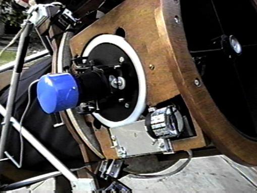
The motor is an SAIA 48 step,12v
stepper motor with a 50:1 gearbox, turning a 240:1 worm gear (HDPE Gear made by
Andy Saulietis). The focuser is an Astro
Systems, Phase 4 focuser. Each step of
the motor rotates the image plane gear 2.25 arcseconds.
The worm gear can swing downward, out of mesh with the
8" dia HDPE gear, to allow manual re-positioning of the camera to adjust
the framing of targets, or the software can drive the motor to reposition the
camera for fine tuning of the framing.
The normal camera I use is a CB245. The camera in the photo is a greyscale
QuickCam.
The field rotation assembly is basically a flange on
the rear (inside) of the gear that rides on two 4" ID bearings. The bearings are held by a ring mounted in a
plate screwed to the rear of the wooden slat in the secondary cage. The flange has a rear plate that is screwed
to the end of the flange and squeezes the two bearings together in the bearing
plate, capturing the gear/flange on the plate.
|
The
mounting plate and bearing ring (backside, away from focuser)
|
The
mounting plate and bearing ring (Top side, towards focuser)
|
Flange
attached to rear of gear
|
|
Rear
Plate (attaches to inner end of flange on gear to capture bearings and
bearing ring onto flange)
|
Disassembled
FR system
|
FR
system together with the secondary cage
slat that the plate attaches to (on the rear) and
the worm/motor
assembly.
|
|
Sec
cage slat with the assembled FR system mounted to it, ready to be mounted in
the sec cage.
|
View
of inside of the assembled sec cage slat, ready to be mounted to the sec
cage. Silver screws attach the plate to
the rear of the sec slat.
|
The
inside of the secondary cage has a "closeout" panel made of
aluminum flashing. The following photo
shows the inside of the secondary cage, the closeout panel, and the
adjustment screws and their locking clamps on the Rear Plate of the Field
Rotation bearing assembly. |
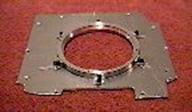
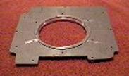
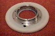
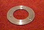
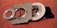
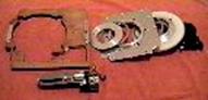
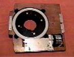
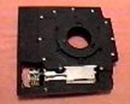
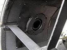
By installing a pinhole light source of a known
diameter pinhole size in the focuser at the focal plane, and then suspending a
video camera over the scope, focused at infinity, looking down into the scope
parallel to the optical axis (offset to the side from the secondary mirror),
you can spin the scope around the azimuth axis and be able to adjust the
vertical stop in the inside of the front panel of the rocker box to have the
scope be perfectly aligned with the azimuth axis in that plane when the scope
is against that adjustable stop. By
adjusting the "fore and aft" position of the altitude trunions along
the Optical Tube Assembly (OTA), the side to side tilt of the scope can be made
to be parallel to the azimuth axis in that plane. The alignment in each plane can be
accurately and easily measured in terms of arc seconds.
With the scope aimed vertically (not necessarily
vertical as with using a bubble level, but instead make it parallel to the
Azimuth axis) with the OTA against the hard stop and secured there with a
bungee cord, suspend a video camera above the scope, looking down into the OTA.
Position it just off set from the secondary mirror to look past it down towards
the Primary. Set the focus at infinity (and turn off autofocus). Take the
camera video feed and send it to a monitor/TV convenient to the scope. At the
eyepiece, you need to have a pinhole light source and have it located at the
focal plane. An easy way to do this is to cut the end off of a plastic 35mm
film can and punch a small hole (less than 1/16" diameter and as round as
possible) in the lid. Re-install the lid on the film can and tape it to a small
flashlight (the lid towards the flashlight). Then just insert the film can into
the focuser and rack the focuser in/out till the lid is at the focal plane. All
of this will result in a collimated light beam being shone at the camcorder. To
initially get the system looking at the light dot, use low power zoom. Once you
have the light dot in the FOV, use as much magnification as possible (I used a
200mm telephoto lens afocally projected onto my camcorder objective lens with
the camcorder set at a zoom of 6x).
Spin
Alignment Setup
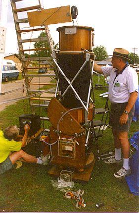
The telescope is aimed vertically and is up against
the adjustable hardstop on the inside of the front panel of the rockerbox.
The video camera is suspended above the telescope
aimed parallel to the optical axis with its focus set at infinity, autofocus turned
off, and its video output sent to a nearby monitor. (The huge ladder holding
the camcorder is used by Larry Mitchell to climb to the eyepiece on his
36"dob!!)
A pinhole light source is inserted into the focuser
and is positioned at the focal plane.
Al Kelly (in the white shirt) is rotating the scope
about the azimuth axis, from one "90 deg" position to the next.
Dick Miller (in the green shirt), is marking the path
of the white dot (the image of the pinhole light source) with a water soluble
pen on the TV monitor, and annotating the path described by the dot with the
rotation position of the mount.
The side to side adjustments (on one of the altitude
trunions) and the fore and aft vertical stop adjustment (the adjustable stop
inside the rockerbox front panel) are adjusted till the dot describes the
smallest circle possible. Then the
adjustments are "locked" in place.
The remaining displacement is measured in terms of
diameters of the dot image. The angular
size of the diameter of the dot image is calculated from the pin hole size and the focal length of the Primary mirror and
camcorder optics, thus allowing you to express the displacement of the dot's
path (the mount's misalignment) in arcseconds.
Altitude Trunion adjuster. The bolts
holding the trunion to the trunion-box are loosened and the nuts on the
adjuster bolt allow the OTA to move "fore & aft" to adjust the
side to side misalignment.
The small flashlight and 35mm film canister used for a
pinhole light source. Punch a small round hole in the lid and measure its
diameter as accurately as possible. Cut the end from the canister, re-install the lid,
and tape the flashlight to the lid.
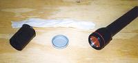
Photo of the flashlight/film canister inserted into
the focuser. Adjust the focuser till the
lid/pinhole is at the focal plane.
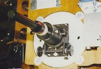
The adjustable hard stop on the
inside of the front panel of the rockerbox. (a carriage bolt in a wooden
plug, secured to the rockerbox via a t-nut and jam-nuts/washers)

As the scope is rotated in Azimuth, the small dot of
light will describe a circle on the TV screen. Pick 4 "cardinal"
points with respect to the ground board. to use as
reference (i.e. call them N, S, E, and W, or 0, 90, 180,and 270). The idea is
that you will adjust one of the altitude sectors fore and aft along the
"X" axis of the OTA, then rotate the rockerbox to see if that made
the circle smaller. Ultimately it will collapse into a line from a circle when
the side to side tilt of the OTA’s "X" axis is finally made
orthogonal to the Altitude axis (and perpendicular to the Azimuth axis). The
next step is to adjust the altitude hard stop on the front of the rockerbox
that limits the OTA altitude to 90 degrees. Adjust it in the same manner as for
the altitude sector adjustment till the motion due to the tube not being
parallel to the azimuth axis in altitude collapses to nothing.
Video on TV screen showing the reflected image of the
secondary mirror and the lighted dot from the pinhole.
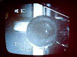
By going back and iterating the adjustments once or
twice, and by using as much magnification as possible, you will end up with the
dot probably describing a small figure 8. This is due to any small astigmatism
in the metal plate on the bottom of the rocker box that forms the bearing
surface and any "noise" in the bearings or bearing surface.
The actual angular errors can be measured quite
accurately, especially if you use high magnification. The size of the dot
(actually the subtended angle) can be calculated by measuring the actual size
of the pinhole in the film can lid and using the formula: (P/F)x(206.265)=D where P is the diameter of the pin hole,
F=focal length of the Primary Mirror, D=arc sec that the Dot image subtends.
Then, the distance the dot wanders from the "center" of the figure it
describes can be measured in terms of dot diameters on the TV screen, and then
multiplied by the calculated angular size of the dot.
A large number of friends
have contributed greatly to the project.
Larry Bell derived a formula
to correct coordinate conversion hysteresis when large values of Z1 and Z2 are
used.
Richard Berry suggested the 3
star initialization routine.
Renato Bonomini contributed
the eyepiece and eyepiece focusing code.
Jack Brindle and a small
group are actively working on a Mac port loosely based on the computerized dob project.
Doug Brown contributed code
and circuitry plans for 5 phase stepper operation.
Tom Cathey worked with me on
the encoders.
Marcello Cucchi and friends
contributed a program that generates a planetary positions data file.
Gilles Cotes contributed
NGC/IC data files.
Donald J. D'Egidio
contributed the AL_DblSt.dat and AL_Urban.dat data files (Astronomical League's
double star and urban club object lists).
Ben Davies contributed
precession/nutation/annual aberration formula and code.
Dale Eason contributed fast
video routines and interrupt timed slewing, in addition to the Messier and
stars to 5 mag data files.
Dave Ek contributed the
altitude offset algorithm.
Mark Ewert contributed code
for site configuration.
Bill Gray worked closely with
me to integrate "Guide" with scope.exe.
Berthold Hamburger designed a
PCB.
David Hutchinson contributed
custom LX200 commands.
Rex Kindell worked on most of
the data files, checking the declination minus situation; also contributed the
solarsys.exe program..
Tom Krajci helped with the
pointing error corrections, homemade worm gears, and contributed the bright
stars catalogs.
Jerry Pinter contributed many
of the object data files and worked with me developing backlash routines.
Bob Norgard contributed the
NTE1857 replacement of the SAA1042 chip:
its wiring and notes.
Vicent Peris contributed the
Hickson Compact Galaxies, Palomar Globulars, Arp's Peculiar Galaxies, Catalog
of Planetary Nebulae, and SAC60 by constellation data files.
Jon Rock showed how to use
the mouse encoders.
Chris
Rowland for source code on unique PWM values for the 2nd motor, and for many
additional scroll commands.
Bob Segrest developed a
microprocessor based encoder interface of great speed.
Chuck Shaw helped develop the
field de-rotation system, spent time debugging the autogeneration of PEC routines,
and has worked to develop a set of configuring instructions.
Pat Sweeney developed a PCB
for the project.
Dave Sopchak contributed the
iterative altitude offset algorithm.
Jean-Charles Vachon
contributed the current limiting circuit.
Don Ware contributred the
Flamsteed data sets along with NGC and IC1-5 data sets; and source code to read
forwards/backwards through the data files; and the user defined hotkeys; and
the polar alignment method for equatorial mounts..
Mark Williams contributed the
autosynchronization of PEC idea and code.
Members of the
scope-drive@yahoogroups.com list have contributed many ideas including hardware
circuitry and operation suggestions.
Many other amateurs have made
suggestions and worked with me to perfect parts of the system.
BBAstroDesigns, Inc. (Seller)
warrants, to the original purchaser only, that goods sold will be free of
material defects in design, materials and workmanship for a period of 90 days
following the date of shipment by Seller to Buyer. Seller will repair or
replace, or refund the purchase price as to, goods that do not conform to the
foregoing warranty, provided the cause of the nonconformity does not arise from
or relate to modification, misuse, or abuse by the customer, and provided a
warranty claim, stating in writing and with reasonable particularity the
claimed nonconformity, and the goods, are delivered to Seller within the 90 day
period. Repair or replacement of the product or refund of the purchase price,
at Seller's sole option, shall be the Buyer's exclusive remedies. Seller shall
not be responsible for any indirect, special or consequential damages arising
from use of the products. This warranty is given in lieu of any other
warranties, express or implied, including of performance, merchantability,
fitness for particular purpose, or arising from course of dealing or usage of
trade. Goods subject to this warranty must be shipped postage pre-paid by Buyer
to the Seller. Some states do not allow the exclusion or limitation of
incidental or consequential damages, so the above limitations may not apply to
you. This warranty gives you specific legal rights, and you may also have other
rights which vary from state to state.
Copyright (C) 1989, 1991 Free Software Foundation, Inc.
Everyone is permitted to copy and distribute
verbatim copies of this license document, but changing it is not allowed.
Preamble
The licenses for most software are designed
to take away your freedom to share and change it. By contrast, the GNU General Public License
is intended to guarantee your freedom to share and change free software--to
make sure the software is free for all its users. This General Public License applies to most
of the Free Software Foundation's software and to any other program whose
authors commit to using it. (Some other
Free Software Foundation software is covered by the GNU Library General Public
License instead.) You can apply it to
your programs, too.
When we speak of free software, we are
referring to freedom, not price. Our
General Public Licenses are designed to make sure that you have the freedom to
distribute copies of free software (and charge for this service if you wish),
that you receive source code or can get it if you want it, that you can change
the software or use pieces of it in new free programs; and that you know you
can do these things.
To protect your rights, we need to make
restrictions that forbid anyone to deny you these rights or to ask you to
surrender the rights. These restrictions translate to certain responsibilities
for you if you distribute copies of the software, or if you modify it.
For example, if you
distribute copies of such a program, whether gratis or for a fee, you must give
the recipients all the rights that you have. You must make sure that they, too, receive or
can get the source code. And you must
show them these terms so they know their rights.
We protect your rights with two steps: (1)
copyright the software, and (2) offer you this license which gives you legal
permission to copy, distribute and/or modify the software. Also, for each author's protection and ours,
we want to make certain that everyone understands that there is no warranty for
this free software. If the software is
modified by someone else and passed on, we want its recipients to know that
what they have is not the original, so that any problems introduced by others
will not reflect on the original authors' reputations.
Finally, any free program is threatened
constantly by software patents. We wish
to avoid the danger that redistributors of a free program will individually
obtain patent licenses, in effect making the program proprietary. To prevent this, we have made it clear that
any patent must be licensed for everyone's free use or not licensed at all.
The precise terms and conditions for copying,
distribution and modification follow.
GNU GENERAL PUBLIC LICENSE
TERMS AND CONDITIONS FOR
COPYING, DISTRIBUTION AND MODIFICATION
0. This License applies to any program or
other work which contains a notice placed by the copyright holder saying it may
be distributed under the terms of this General Public License. The "Program", below, refers to any
such program or work, and a "work based on the Program" means either
the Program or any derivative work under copyright law: that is to say, a work
containing the Program or a portion of it, either verbatim or with
modifications and/or translated into another language. (Hereinafter, translation is included without
limitation in the term "modification".) Each licensee is addressed as
"you".
Activities other than
copying, distribution and modification are not covered by this License; they
are outside its scope. The act of
running the Program is not restricted, and the output from the Program is
covered only if its contents constitute a work based on the Program
(independent of having been made by running the Program). Whether that is true
depends on what the Program does.
1. You may copy and distribute verbatim
copies of the Program's source code as you receive it, in any medium, provided
that you conspicuously and appropriately publish on each copy an appropriate
copyright notice and disclaimer of warranty; keep intact all the notices that
refer to this License and to the absence of any warranty; and give any other
recipients of the Program a copy of this License along with the Program.
You may charge a fee for the
physical act of transferring a copy, and you may at your option offer warranty
protection in exchange for a fee.
2. You may modify your copy or copies of the
Program or any portion of it, thus forming a work based on the Program, and
copy and distribute such modifications or work under the terms of Section 1
above, provided that you also meet all of these conditions:
a) You must cause the modified files to
carry prominent notices stating that you changed the files and the date of any
change.
b) You must cause any work that you
distribute or publish, that in whole or in part contains or is derived from the
Program or any part thereof, to be licensed as a whole at no charge to all
third parties under the terms of this License.
c) If the modified program normally reads
commands interactively when run, you must cause it, when started running for
such interactive use in the most
ordinary way, to print or display an announcement including an appropriate
copyright notice and a notice that
there is no warranty (or else, saying that you provide a warranty) and that
users may redistribute the program under
these conditions, and telling the user how to view a copy of this
License. (Exception: if the Program
itself is interactive but does not normally print such an announcement, your
work based on the Program is not required to print an announcement.)
These requirements apply to
the modified work as a whole. If
identifiable sections of that work are not derived from the Program, and can be
reasonably considered independent and separate works in themselves, then this
License, and its terms, do not apply to those sections
when you distribute them as separate works.
But when you distribute the same sections as part of a whole which is a
work based on the Program, the distribution of the whole must be on the terms
of this License, whose permissions for other licensees extend to the entire
whole, and thus to each and every part regardless of who wrote it.
Thus, it is not the intent of
this section to claim rights or contest your rights to work written entirely by
you; rather, the intent is to exercise the right to control the distribution of
derivative or collective works based on the Program.
In addition, mere aggregation
of another work not based on the Program with the Program (or with a work based
on the Program) on a volume of a storage or distribution medium does not bring
the other work under the scope of this License.
3. You may copy and distribute the Program
(or a work based on it, under Section 2) in object code or executable form
under the terms of Sections 1 and 2 above provided that you also do one of the
following:
a) Accompany it with the complete
corresponding machine-readable source code, which must be distributed under the
terms of Sections 1 and 2 above on a medium customarily used for software
interchange; or,
b) Accompany it with a written offer, valid
for at least three years, to give any third party, for a charge no more than
your cost of physically performing source distribution, a complete
machine-readable copy of the corresponding source code, to be distributed under
the terms of Sections 1 and 2 above on a medium customarily used for software
interchange; or,
c) Accompany it with the information you
received as to the offer to distribute corresponding source code. (This alternative is allowed
only for noncommercial distribution and only if you received the program in
object code or executable form with such an offer, in accord with
Subsection b above.)
The source code for a work
means the preferred form of the work for making modifications to it. For an executable work, complete source code
means all the source code for all modules it contains, plus any associated
interface definition files, plus the scripts used to control compilation and
installation of the executable. However,
as a special exception, the source code distributed need not include anything
that is normally distributed (in either source or binary form) with the major
components (compiler, kernel, and so on) of the operating system on which the
executable runs, unless that component itself accompanies the executable.
If distribution of executable
or object code is made by offering access to copy from a designated place, then
offering equivalent access to copy the source code from the same place counts
as distribution of the source code, even though third parties are not compelled
to copy the source along with the object code.
4. You may not copy, modify, sublicense, or
distribute the Program except as expressly provided under this License. Any attempt otherwise to copy, modify,
sublicense or distribute the Program is void, and will automatically terminate
your rights under this License. However, parties who have received copies, or
rights, from you under this License will not have their licenses terminated so
long as such parties remain in full compliance.
5. You are not required to accept this
License, since you have not signed it.
However, nothing else grants you permission to modify or distribute the
Program or its derivative works. These actions
are prohibited by law if you do not accept this License. Therefore, by modifying or distributing the
Program (or any work based on the Program), you indicate your acceptance of
this License to do so, and all its terms and conditions for copying, distributing
or modifying the Program or works based on it.
6. Each time you redistribute the Program (or
any work based on the Program), the recipient automatically receives a license
from the original licensor to copy, distribute or modify the Program subject to
these terms and conditions. You may not
impose any further restrictions on the recipients' exercise of the rights
granted herein. You are not responsible for enforcing compliance by third
parties to this License.
7. If, as a consequence of a court judgment
or allegation of patent infringement or for any other reason (not limited to
patent issues), conditions are imposed on you (whether by court order,
agreement or otherwise) that contradict the conditions of this License, they do
not excuse you from the conditions of this License. If you cannot distribute so as to satisfy
simultaneously your obligations under this License and any other pertinent
obligations, then as a consequence you may not distribute the Program at
all. For example, if a patent license
would not permit royalty-free redistribution of the Program by all those who
receive copies directly or indirectly through you, then the only way you could
satisfy both it and this License would be to refrain entirely from distribution
of the Program.
If any portion of this
section is held invalid or unenforceable under any particular circumstance, the
balance of the section is intended to apply and the section as a whole is
intended to apply in other circumstances.
It is not the purpose of this
section to induce you to infringe any patents or other property right claims or
to contest validity of any such claims; this section has the sole purpose of
protecting the integrity of the free software distribution system, which is
implemented by public license practices.
Many people have made generous contributions to the wide range of
software distributed through that system in reliance on consistent application
of that system; it is up to the author/donor to decide if he or she is willing
to distribute software through any other system and a licensee cannot impose
that choice.
This section is intended to
make thoroughly clear what is believed to be a consequence of the rest of this
License.
8. If the distribution and/or use of the
Program is restricted in certain countries either by
patents or by copyrighted interfaces, the original copyright holder who places
the Program under this License may add an explicit geographical distribution
limitation excluding those countries, so that distribution is permitted only in
or among countries not thus excluded. In
such case, this License incorporates the limitation as if written in the body
of this License.
9. The Free Software Foundation may publish
revised and/or new versions of the General Public License from time to
time. Such new versions will be similar
in spirit to the present version, but may differ in detail to address new
problems or concerns.
Each version is given a
distinguishing version number. If the
Program specifies a version number of this License which applies to it and
"any later version", you have the option of following the terms and
conditions either of that version or of any later version published by the Free
Software Foundation. If the Program does
not specify a version number of this License, you may choose any version ever
published by the Free Software Foundation.
10. If you wish to incorporate parts of the
Program into other free programs whose distribution conditions are different,
write to the author to ask for permission.
For software which is copyrighted by the Free Software Foundation, write
to the Free Software Foundation; we sometimes make exceptions for this. Our decision will be guided by the two goals
of preserving the free status of all derivatives of our free software and of
promoting the sharing and reuse of software generally.
NO WARRANTY
11. BECAUSE THE PROGRAM IS LICENSED FREE OF
CHARGE, THERE IS NO WARRANTY FOR THE PROGRAM, TO THE EXTENT PERMITTED BY
APPLICABLE LAW. EXCEPT WHEN OTHERWISE
STATED IN WRITING THE COPYRIGHT HOLDERS AND/OR OTHER PARTIES PROVIDE THE
PROGRAM "AS IS" WITHOUT WARRANTY OF ANY KIND, EITHER EXPRESSED OR
IMPLIED, INCLUDING, BUT NOT LIMITED TO, THE IMPLIED WARRANTIES OF
MERCHANTABILITY AND FITNESS FOR A PARTICULAR PURPOSE. THE ENTIRE RISK AS TO THE QUALITY AND
PERFORMANCE OF THE PROGRAM IS WITH YOU.
SHOULD THE PROGRAM PROVE DEFECTIVE, YOU ASSUME THE COST OF ALL NECESSARY
SERVICING, REPAIR OR CORRECTION.
12. IN NO EVENT UNLESS REQUIRED BY APPLICABLE
LAW OR AGREED TO IN WRITING WILL ANY COPYRIGHT HOLDER, OR ANY OTHER PARTY WHO
MAY MODIFY AND/OR REDISTRIBUTE THE PROGRAM AS PERMITTED ABOVE, BE LIABLE TO YOU
FOR DAMAGES, INCLUDING ANY GENERAL, SPECIAL, INCIDENTAL OR CONSEQUENTIAL
DAMAGES ARISING OUT OF THE USE OR INABILITY TO USE THE PROGRAM (INCLUDING BUT
NOT LIMITED TO LOSS OF DATA OR DATA BEING RENDERED INACCURATE OR LOSSES
SUSTAINED BY YOU OR THIRD PARTIES OR A FAILURE OF THE PROGRAM TO OPERATE WITH
ANY OTHER PROGRAMS), EVEN IF SUCH HOLDER OR OTHER PARTY HAS BEEN ADVISED OF THE
POSSIBILITY OF SUCH DAMAGES.
END OF TERMS AND CONDITIONS