the complete hand paddle and stepper motor driver circuit...
The TTL 7404 hex inverters can source 40 milliamps. At 5 volts, this current draw from each pin of the hex inverters is limited by the 470 ohm resistors to 10 milliamps. The transistors will amplify this current 800-1200 times. So motors up to 10 amps can be used. Most traces on circuit boards and point to point wiring will limit this figure closer to 3 amps.
Shown is the circuit for 4 winding steppers. The software can handle 5 phase steppers with a different circuit. See the software config webpage for details.
This is the complete circuit trace of how a single parallel port
line controls a single stepper winding (7408 AND gates can substitute
for the hex inverters - tie one of the AND gate input lines
permanently to +5vdc):
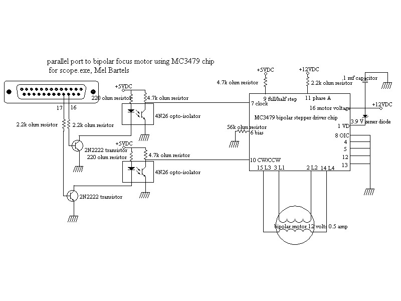
The circuit diagram for the optional focuser motor
a picture of the electronics box.
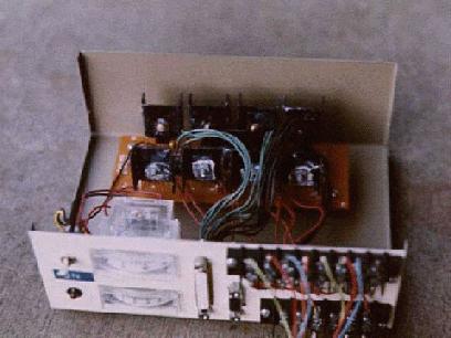
I added a voltmeter and ammeter to gauge battery voltage and motor current draw. I recommend placing all outside cabling sockets and terminals on the front or side of the box. The circuit is simple enough to use point to point wiring. Double and triple check all connections, tracing out all wires by hand, and use a ohmmeter to check for shorts. The power diode/ zener diode network is essential to prevent destruction of the transitors due to back e.m.f. from the motors. These voltage spikes will also make short work of the parallel port. Use a 6 volt battery for initial testing so that if there should be a wiring problem, the parallel port will not be risked.
Considering the relatively low 6 to 12 volts DC involved, and the simple drive circuit, isolation of the laptop/PC from the drive circuit with opto-isolators is not strictly called for. If you power the steppers with 24 volts or higher, you should consider including opto-isolators.
The PC generates voltage waveforms for the four stepper windings and outputs them via the PC parallel port resulting in a very simple drive circuit. 74LS04 hex inverters receive the output from the parallel port and provide adequate current to drive the power transistors. The power transistors should be heat-sunk.
The handpad uses the 4 bits of parallel port input from parallel port base +1, and an external connection of +5 volts DC for a total of 5 lines. A long 9-pin PC serial cable is used. The normally open momentary push buttons are used for directional control. The 3-way switch is used to mark initializations, and to start and stop advanced functions, while the 2-way switch set the speed: either slow microstepping or fast halfstepping. All lines tie to ground via 220 ohm resistors so that when no button or switch is activated, the handpad outputs go to ground, or logical low. When pushing a button or moving a switch, + 5 volts DC is applied to the appropriate bit(s) of the parallel port. Some of the buttons and switches are tied to more than one bit. Diodes are placed on the buttons and switches outputs to insure that only the bits desired are activated. The remaining parallel port pins of 18 through 25 are grounds.
parallel port 25 pin connector pin-out:
2 altitude
stepper motor - red
3 altitude stepper motor - green
4
altitude stepper motor - red/white
5 altitude stepper motor -
green/white
6 azimuth stepper motor - red
7 azimuth stepper
motor - green
8 azimuth stepper motor - red/white
9 azimuth
stepper motor - green/white
10 handpad input (pulled to ground
via 220 ohm resistor)
11 handpad input (pulled to ground via 220
ohm resistor)
12 handpad input (pulled to ground via 220 ohm
resistor)
13 handpad input (pulled to ground via 220 ohm
resistor)
18-25 ground
optional pin-outs:
if using optional pulse and direction control:
2 =
altitude/declination pulse
3 = altitude/declination direction
4
= azimuth/right ascension pulse
5 = azimuth/right ascension
direction
6 = altitude/declination power on
7 = azimuth/right
ascension power on
15, 16, 17, or 10+12+13: optional PEC automatic synchronization signals
1 optional field rotation or focuser motor pulse
14 optional
field rotation or focuser motor direction
16 optional focuser
motor pulse
17 optional focuser motor direction
1 optional DC motor slow focus control out
14 optional DC motor
slow focus control in
16 optional DC motor fast focus control
out
17 optional DC motor fast focus control in
1 optional auxiliary or external control ( dome, etc) via
handpaddle 'up' button
14 optional auxiliary or external control
dome, etc) via handpaddle 'down' button
16 optional auxiliary or
external control ( dome, etc) via handpaddle ' clockwise' button
17
optional auxiliary or external control ( dome, etc) via handpaddle
'counter clockwise' button
16 optional 5th phase altitude stepper
17 optional 5th phase
azimuth stepper
pin assignments and their relation to control input:
A motor CW  = handpad up   = mouse up (1 click)    = aux 1  = mouse focus slow plus  = LX200 focus out
A motor CCW = handpad down = mouse down (2 clicks) = aux 14 = mouse focus slow minus = LX200 focus in
Z motor CW  = handpad CW   = mouse right (3 clicks)= aux 16 = mouse focus fast plus  = LX200 focus out
Z motor CCW = handpad CCW  = mouse left (4 clicks) = aux 17 = mouse focus fast minus = LX200 focus in

handpad CW  + MsSpeed = handpad focus slow plus
handpad CCW + MsSpeed = handpad focus slow minus

pport pin 1 = field rotation pulse or focus pulse
pport pin 14 = field rotation direction or focus direction, on = CW = out = plus
pport pin 16 = focus pulse
pport pin 17 = focus direction, on = CW = out = plus
handpad:
3-way switch left, for initializing, and doing
other tasks, activates pins 13,10
3-way switch middle, neutral -
does nothing, activates nothing
3-way switch right, also for
initializing, and doing other tasks, activates pins 12,10
2-way
switch left, slow microstepping, activates line 11
2-way switch
right, fast halfstepping, activates nothing
upper button,
momentary on = Up, activates pin 13
lower button, momentary on =
Down, activates pin 12
left button, momentary on = CCW, activates
pin 10
right button, momentary on = CW, activates pins 13, 12
bipolar wiring:
The InvertOutput may need to be changed
(for unipolar)
1 2 4 8
1 0 0 0
1 0 0 1
0 0 0 1
0 0 1 1
0 0 1 0
0 1 1 0
0 1 0 0
1 1 0 0
for bipolar
1 2 4 8
1 0 0 0
1 0 1 0
0 0 1 0
0 1 1 0
0 1 0 0
0 1 0 1
0 0 0 1
1 0 0 1
Current limiting:
Jean-Charles Vachon's PEC circuit
Jean-Charles_Vachon__Pec.pdf
Jena-Charles
Vachon's current limiting circuit for the pcb with opto-isolators
Jean-Charles_Vachon__Limiter.pdf
Jena-Charles
Vachon's preferred current limiting circuit
Jean-Charles_Vachon__Preferred_current_limiter.PDF
another limiting circuit by Sigifredo Cruz Rojas http://mantsoft.googlepages.com/Limitcircuit.GIF
Doug Brown's 5 phase stepper circuitry

