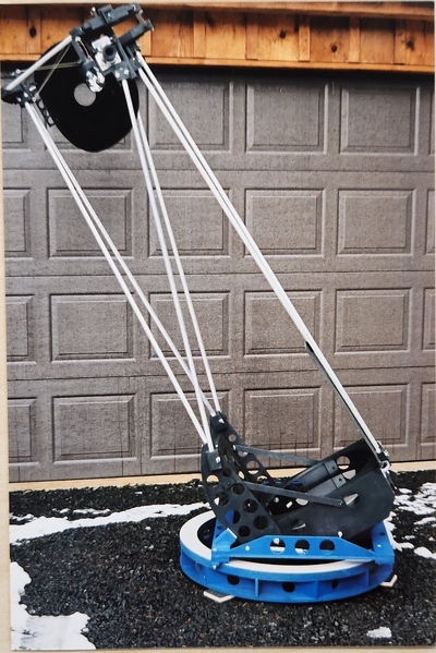
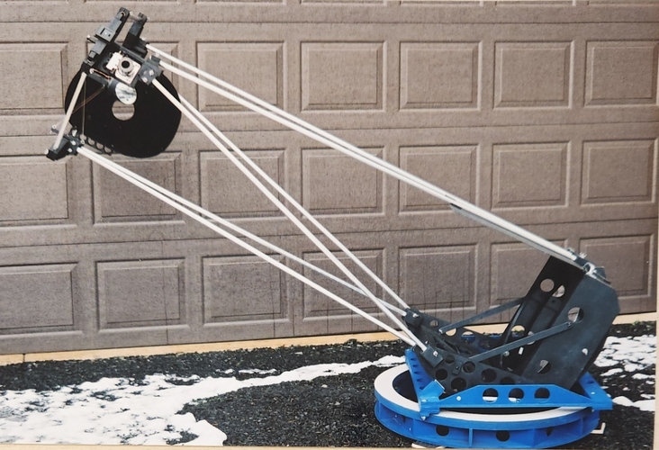
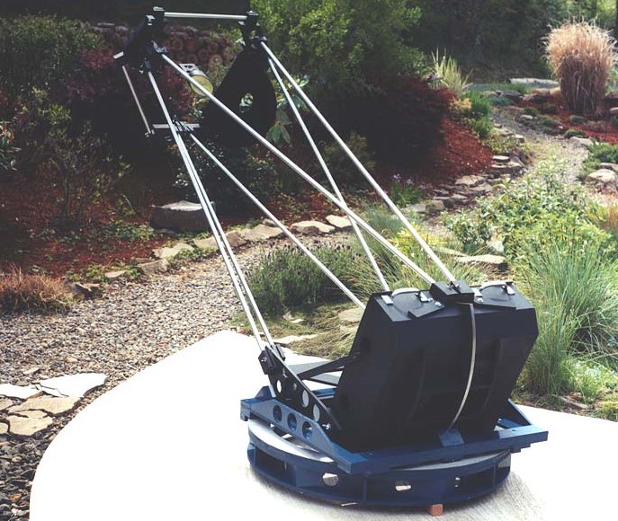
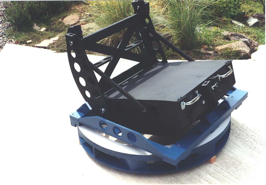
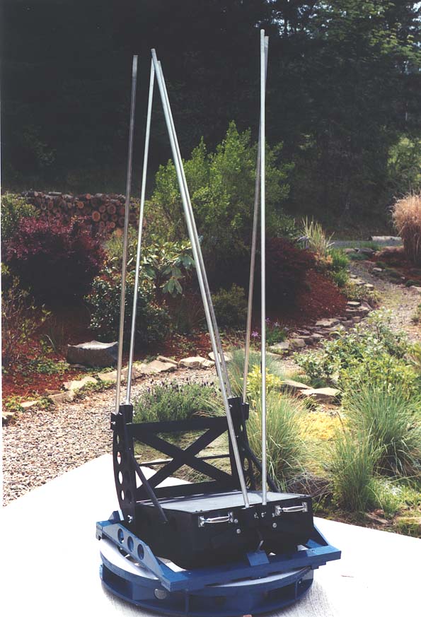
 trilateral mount showing tail fin segmented altitude rim, flex rocker
with base ring, 6 truss tubes, triangular upper end
trilateral mount showing tail fin segmented altitude rim, flex rocker
with base ring, 6 truss tubes, triangular upper end
Features
In 2001, looking for a way to carry my 20 inch through narrow doors, I hit upon the idea of separating the altitude bearings into two 90 degree segments, with the forward segments pivoting upward against the mirror box face. I instantly saw that I could consolidate the back segments into a single tail fin, adopting a three point altitude bearing design. Inspired by Dan Gray's 14 inch, I placed the three azimuth bearing points directly underneath the altitude points, letting the now flattened rocker square become thin and flexible, and put the whole assembly upon a strong rigid base ring. I extended the triangle concept to the upper end, using truss tubes connected by wooden joints. The upper end is attached to the mirror box with six truss tubes. I designed a three arm wire spider that is extremely strong using 22 gauge wire under low tension.
The mount starts with the concept of a large rigid base ring. On top of that is a flexible flattened square where the three altitude bearing points sit directly on top of the three azimuth bearing points. The folding mirror box with three half-altitude bearing rims nestles down into the flex rocker. As the scope is aimed skyward, the mirror box swings down into the space where the ground board and rocker base board would otherwise be located. This achieves a wide base stance relative to the low center of gravity of the tube assembly. From Egyptian pyramids to vocal choirs, a strong structure consists of a solid wide base gradually narrowing to the top.
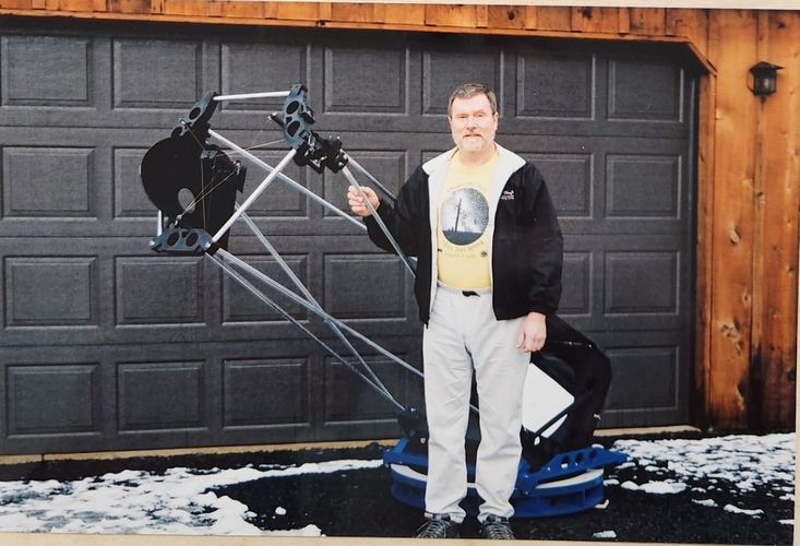
The tube assembly without optics weighs 25 pounds. The optics weigh 50 pounds. The rocker and base weigh 20 pounds. The heaviest piece that I carry is the fold-up mirror box at 62 pounds.
Dan Gray's 14 inch uses a rigid base ring and flat flex rocker with a four point stance. Unknown to me at the time, John Sherman had also designed and built a flex rocker. Also unknown to me, Clive Milne in Australia was working on a three point segmented altitude rim stance for his large binocular scope. The outsides of the twin tubed binocs carry the forward segment of the altitude rim with the tail fin between the two tubes. Finally, the ARC 3.5 meter scope at Apache Point in New Mexico uses a tail fin altitude rim. Greg Babcock's 24 inch also uses a rigid base ring where the scope swings through for lowest possible center of gravity and eyepiece height.
Click on any image to load a larger detailed image.
trilateral mount showing tail fin segmented altitude rim, flex rocker
with base ring, 6 truss tubes, triangular upper end
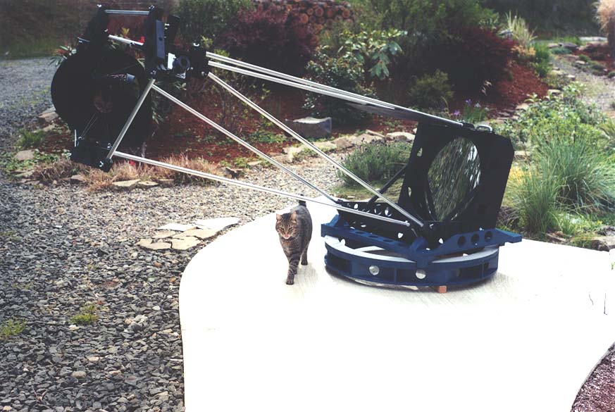 trilateral mount showing triangular upper end, baffle, 6 truss tubes,
and Vincent the astro-cat
trilateral mount showing triangular upper end, baffle, 6 truss tubes,
and Vincent the astro-cat
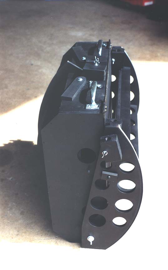 folded mirror box ready for transport: forward segments of altitude
rims are folded up against face of mirror box; made from ½
inch apple plywood, weight with 50 pound mirror is about 62 pounds
folded mirror box ready for transport: forward segments of altitude
rims are folded up against face of mirror box; made from ½
inch apple plywood, weight with 50 pound mirror is about 62 pounds
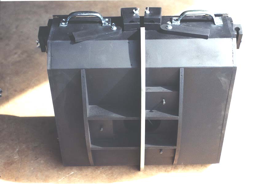 back side of mirror box showing altitude rim tail fin and collimation
points
back side of mirror box showing altitude rim tail fin and collimation
points
 PLOP designed 9 point flotation cell (deformation on order of 1/100
wave), edge support is two teflon blocks placed at 90 degree angle
(RN Wilson's Reflecting Telescope Optics I and II shows how this edge
support prevents astigmatism by setting up two planes of folding that
cancel each out thanks to the 90 degree angle - think of how a piece
of paper is stiffened when creased on side and bottom). For
comparisons of mirror support designs, see
http://pong.telerama.com/~mdholm/atm/cells/compare.html
PLOP designed 9 point flotation cell (deformation on order of 1/100
wave), edge support is two teflon blocks placed at 90 degree angle
(RN Wilson's Reflecting Telescope Optics I and II shows how this edge
support prevents astigmatism by setting up two planes of folding that
cancel each out thanks to the 90 degree angle - think of how a piece
of paper is stiffened when creased on side and bottom). For
comparisons of mirror support designs, see
http://pong.telerama.com/~mdholm/atm/cells/compare.html
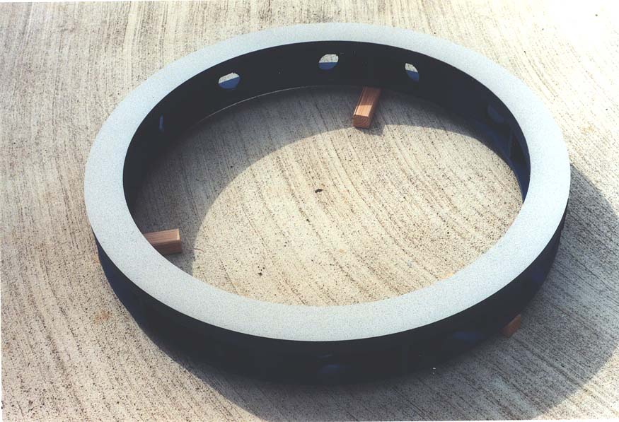 base ring from ½ inch apple plywood: 38 inches outside
diameter x 32 inches inside diameter x 5 inches tall, faced with
formica
base ring from ½ inch apple plywood: 38 inches outside
diameter x 32 inches inside diameter x 5 inches tall, faced with
formica
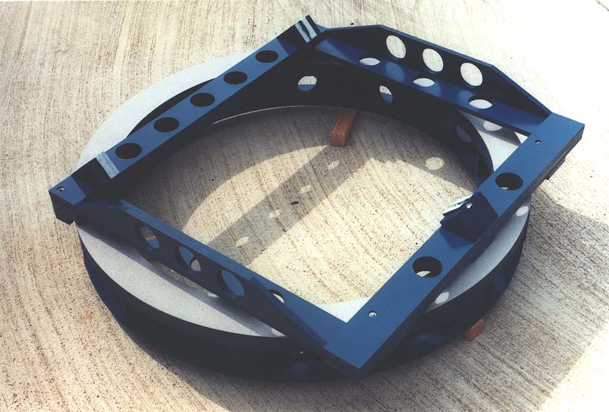 flattened flex rocker with 3 point support sitting on base ring; 4
outside keepers restrain flex rocker's lateral motion
flattened flex rocker with 3 point support sitting on base ring; 4
outside keepers restrain flex rocker's lateral motion
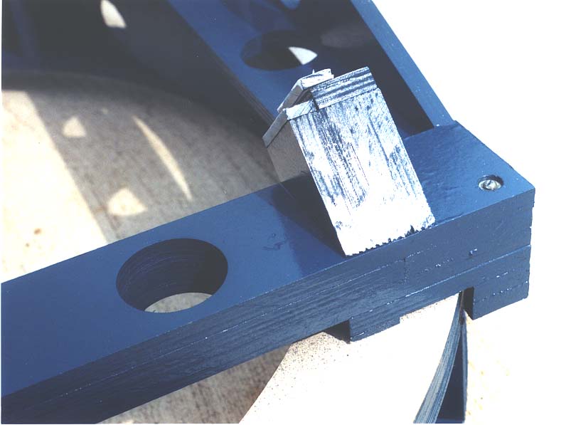 bearing detail showing altitude bearing on top and azimuth bearing
underneath; note side keeping teflon pad; tight side keeping pads
must be installed on front and back altitude bearing points to
prevent lateral skidding of scope when pushed in azimuth
bearing detail showing altitude bearing on top and azimuth bearing
underneath; note side keeping teflon pad; tight side keeping pads
must be installed on front and back altitude bearing points to
prevent lateral skidding of scope when pushed in azimuth
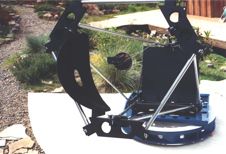
 unfolded mirror box cradled in flex rocker with base ring
 the six 0.75 inch diameter thin walled truss tubes have been slid
into their holders on the mirror box: holders built up from three ½
inch apple plywood layers with ¾ inch hole drilled through
the six 0.75 inch diameter thin walled truss tubes have been slid
into their holders on the mirror box: holders built up from three ½
inch apple plywood layers with ¾ inch hole drilled through
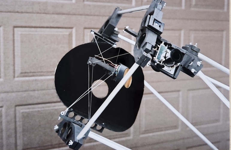
 triangular upper end with 3 vane wire spider and baffle system: wire
spider extremely strong, entire scope can easily be moved about by
gripping the diagonal hub; advantages of wire spiders are reduced
diffraction thanks to thin cross section (traditional spider vanes
can twist slightly presenting a thickened cross-section), eliminated
thermal effects (standard spider vanes cool below air temperature and
may capture a boundary layer of air that refracts light), reduced
rotational vibration in windy conditions (an issue on larger scopes),
lightweight, and low cost
triangular upper end with 3 vane wire spider and baffle system: wire
spider extremely strong, entire scope can easily be moved about by
gripping the diagonal hub; advantages of wire spiders are reduced
diffraction thanks to thin cross section (traditional spider vanes
can twist slightly presenting a thickened cross-section), eliminated
thermal effects (standard spider vanes cool below air temperature and
may capture a boundary layer of air that refracts light), reduced
rotational vibration in windy conditions (an issue on larger scopes),
lightweight, and low cost
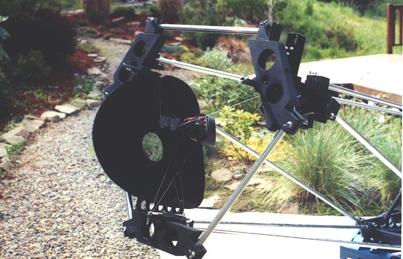 another view of the triangular upper end showing the wire spider and
diagonal baffle: diagonal baffle made from ¼ inch thick very
lightweight sign board bent using a rolling pin
another view of the triangular upper end showing the wire spider and
diagonal baffle: diagonal baffle made from ¼ inch thick very
lightweight sign board bent using a rolling pin
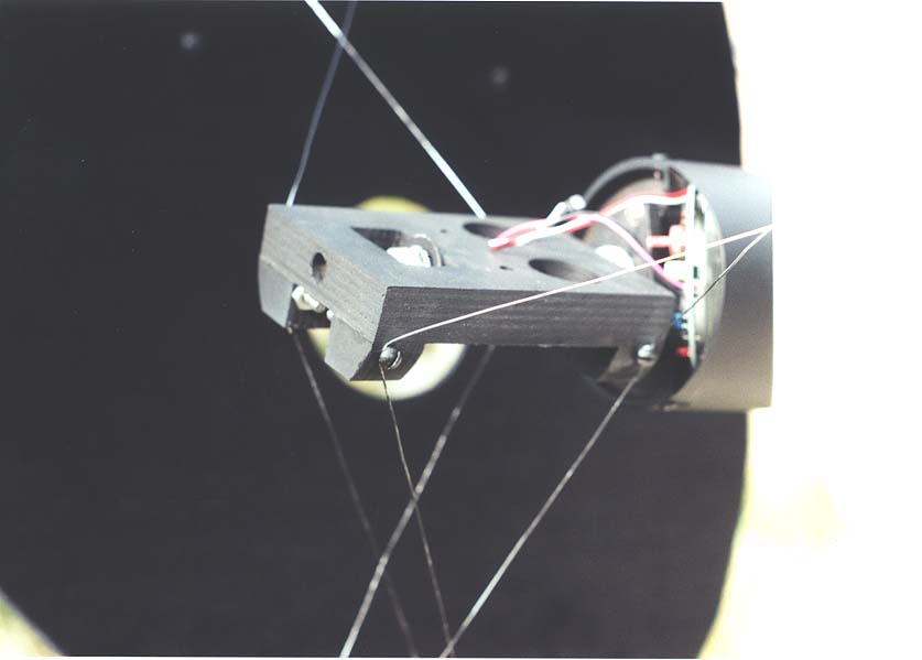 closeup of the diagonal hub and 3 vane 22 gauge wire spider: a single
8 foot piece of wire is threaded through eyebolts and around heads of
machine bolts while hub held in place with keeper wood piece, then
eyebolts and machine bolts are carefully tightened until wire is
under moderately low tension; wires crisscross every pass from front
of hub to back of aluminum channel eyebolt holders and visa versa
closeup of the diagonal hub and 3 vane 22 gauge wire spider: a single
8 foot piece of wire is threaded through eyebolts and around heads of
machine bolts while hub held in place with keeper wood piece, then
eyebolts and machine bolts are carefully tightened until wire is
under moderately low tension; wires crisscross every pass from front
of hub to back of aluminum channel eyebolt holders and visa versa
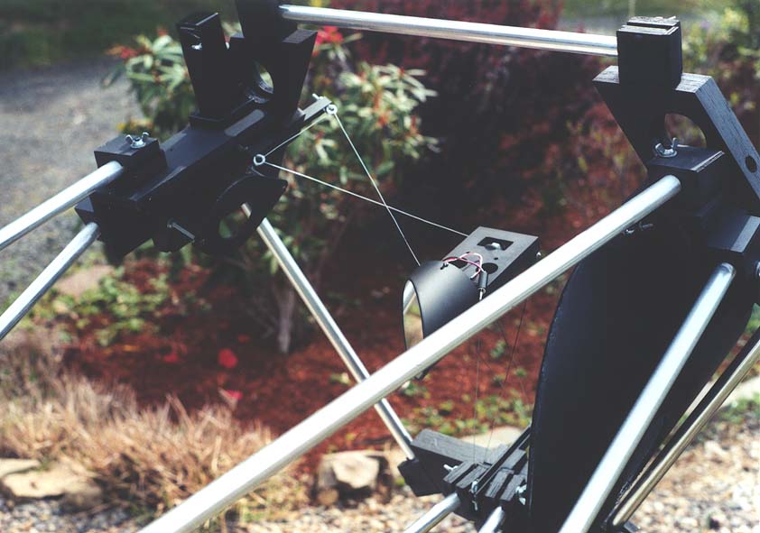 the focuser baffle is placed below the focuser mounting plate: this
reduces the size of the diagonal baffle; crisscrossed wire spider and
aluminum channel eyebolt holders are also visible; electronics behind
the diagonal is for a heater – essential when using open ended
telescopes to prevent dewing of the secondary
the focuser baffle is placed below the focuser mounting plate: this
reduces the size of the diagonal baffle; crisscrossed wire spider and
aluminum channel eyebolt holders are also visible; electronics behind
the diagonal is for a heater – essential when using open ended
telescopes to prevent dewing of the secondary
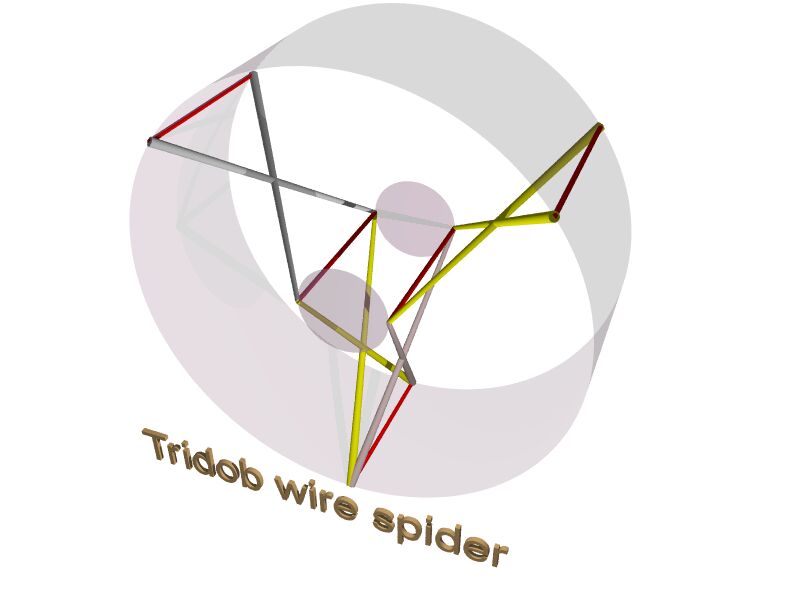 spider schematic
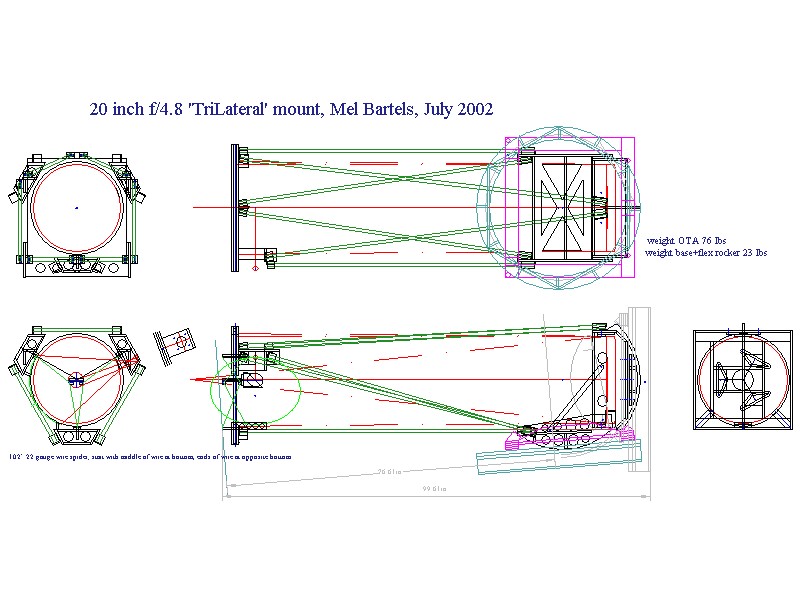 CAD
CAD
Additional images