The mirror's overall extreme meniscus shape, where the sagitta or depth in the mirror's center matches the mirror's thickness, can be thought of as the total thickness from forward edge to the center-back. This 25 inch mirror is then 1.3 inches thick, with the change being that the back edge is 'ground away' from flat to a curve. David Davis' pie-plate design where a cylindrical rim is attached to the edge is promising. Grinding away the edge into a meniscus shape saves weight and moves the blank closer to a conical shape, which we know, if center supported, deforms into a new approximate parabola will little error. It may be more predictive to note the center thickness of mirrors than the edge thickness.
I built a 9 ring back support for final star testing when figuring the mirror. This is analogous to a 27 point support that consists of 9 triangles of 3 pts each. To my great surprise I didn't see appreciable deformation with the 9 rings at highest magnification. Each of the 9 rings is shaped to fit the mirror's back side. This reduces the bending and shearing. Read more on the star test and making of the mirror.
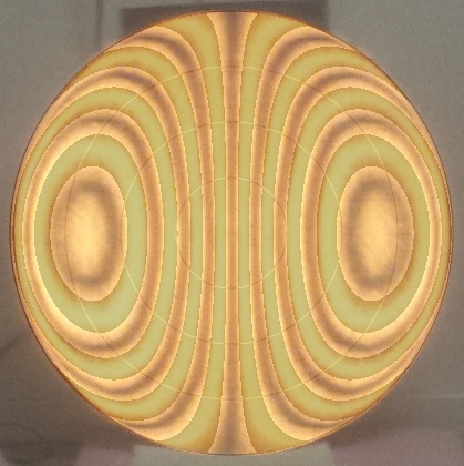
Testing during figuring consisted of resting the mirror against the tool that I used to grind the back regular with a non-stick mat as a spacer. I was surprised by how little deformation resulted from resting the mirror on its bottom point. Check out the Ronchigram where I overlay the actual bands with the theoretically calculated bands that shows minimal deformation at the mirror's bottom.
At this point I knew that the 2 pt edge support would work as I've used it extensively. As R.N.Wilson notes, the primary benefit is cancellation of low-order astigmatism. I use Teflon (PTFE) for the edge supports. I like the whiskers approach if the mirror's edge gets caught up.
I can catch the mirror's edge in a bad position by pointing the scope horizontally, lifting the mirror's bottom edge with my fingers a fraction of an inch, then letting it settle forward or above the back support points. When I point the scope upward, the stars are lines! If I point the scope vertically, allowing the mirror to settle, then point back downward, all is fine. If this proves too finicky, I can replace the edge support blocks as I made them a separate bolt-on assembly.
I considered Hubble's mirror cell design, PLOP and other FEA, along with Luc Arnold's work on meniscus mirrors from the 1990s (see SPIE publications). There are two approaches: 1) the conservative approach where there cannot be enough support points, and 2) the engineering approach where one asks what support points are sufficient. The latter calls for modeling the support pads that can reduce bending and shear directly over the support point, re-focusing the mirror cell deformations into best-fit paraboloid and taking into account integrated pointing angle which reduces the gravity induced deformations, along with verifying interferograms of the mirror in its cell.
I was very worried when I started this project that the major obstacle was going to be the mirror cell. This turned out not to be the case: the major obstacle is parabolizing all those waves of correction into the glass!
eod