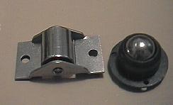
On the left is a metal drawer roller and on the right is a 3/4 inch caster ball bearing transfer unit - $2 and $5 respectively at the local hardware store.
Rigid dobsonian mounts offer large bearing surfaces to attach drives. The scope can be driven using one of several different methods. A direct-drive system is composed of a threaded rod pressed against the rim of a large drive circle. Threads are impressed into the rim of the drive circle either by JB-Weld, wood putty, or fiberglass. See an article of mine in Sky and Telescope magazine, April, '79 for a description of this method. My article was inspired by an earlier article in June '74 Sky and Telescope.
Many modern professional scopes use large circular rollers driven by machined shafts. These avoid the errors inherent in worm and gear drives. Worm and gear errors include periodic and erratic errors. Periodic errors are caused by the elliptical shape of the gear and by mis-centering of the worm on its shaft. Erratic errors are caused by tooth to tooth differences and by backlash when the drive changes direction.
By using a gear reducer in the preliminary stage and a roller drive for the final stage, the errors present in the gear reducer are divided by the ratio of the final roller. For instance, if the gear reducer has an error of one arc minute, and the final roller drive ratio is 30:1, then the actual error present at the eyepiece will be two arc seconds.
The bearing surfaces should be converted to ball-bearings riding underneath Formica in smaller scopes, and aluminum or galvanized metal sheet in larger sizes. Face the altitude bearing rims with thin strips of aluminum. Substitute a drive shaft or drive hub for one of the four altitude bearing points. Attach a gear reducer powered by a stepper motor to this drive shaft. The azimuth drive is a drive shaft with a conical machined end that rides underneath the rocker bottom, faced with a thin metal plate. The other two contact points are ball bearings. Since the rollers are very large, the scope has a very high inherent stiffness. One advantage of a dobsonian over an equatorial is that gravity naturally tensions the rollers and drive shafts.
On
the left is a metal drawer roller and on the right is a 3/4 inch
caster ball bearing transfer unit - $2 and $5 respectively at the
local hardware store.
Try searching on 'roller drive', and 'toothed belt drive', and 'cable drive'
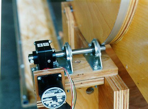
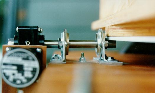
Don Clement's cable driveHere is a view of the altitude axis and a view of the azimuth of a typical roller drive with small palm sized gear reducer in front of the stepper motor. Notice how the azimuth axis is slightly tipped and the end of the drive shaft is conical.
|
|
|