The Zip Dob
by Mel Bartels
"My God, it's full of stars!" --- 2001, a Space Odyssey. Star fever, nebula fever, aperture fever, field fever!
Astronomy is like life. The more you open your eyes the more surprises you'll see. The most profound surprises are the silent ones that unexpectedly tap your shoulder. The panoramic composition of multiple deep sky objects backed by considerable aperture leaves visual memories that I can never forget. I call the experience Wide Angle Large Aperture observing, WALA!
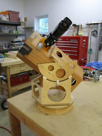
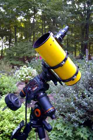
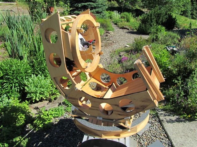
My 13.2 inch [34cm] f/3.0 is conceived to squeeze as much aperture as possible into a compact package that fits into a back seat of a car, yet can be carried as a single unit in my arms to an observing spot. It unfolds from its travel configuration to its observing configuration in about one minute. At a recent star party, a gentleman came by and asked if it was an eight inch or ten inch scope. When I explained that it was a 13 inch, he apologized. No apologies needed that was a compliment!
Like many amateur projects, I worked on it more off than on. I received the slumped mirror from Richard Schwartz in 2000, grinding it back from f2.5 to f3.0 in 2001, thinking that the then current coma corrector had no chance at f2.5. I set it aside until 2007, polishing it out and finishing parabolizing in 2008. I finished the folding mount in 2009.
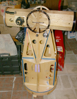
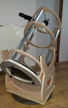
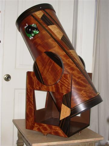
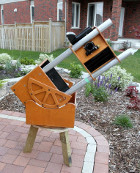
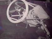
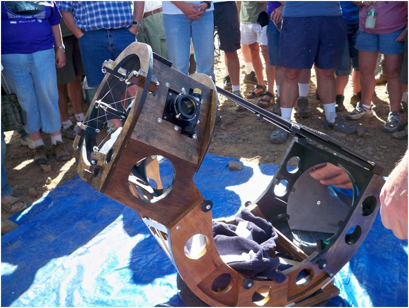
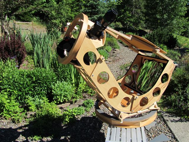
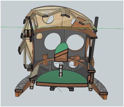
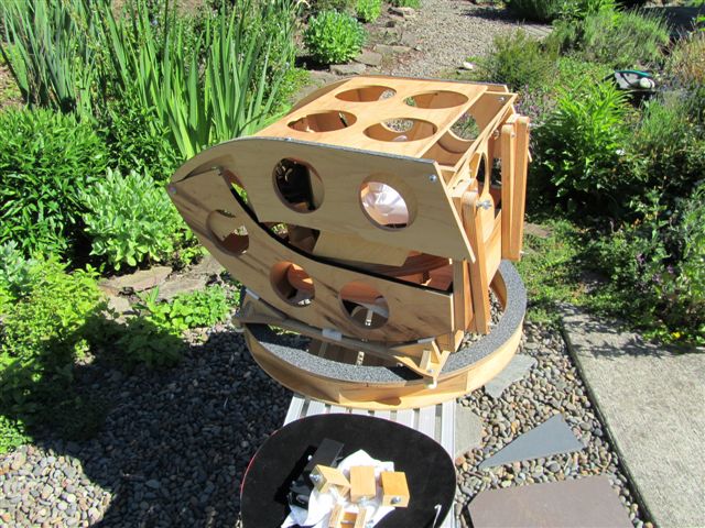
The first image is from the Oregon Star Party 2010 Telescope Walkabout. The second image is my 2nd generation design: one fewer fold with less volume.
The evolution of Newtonian focal ratios closely mirrors eyepiece technology. In fact, it can be said without exaggeration that the ever increasing sophistication of eyepiece design is an enabling technology. As better corrected eyepieces yielded better views in fast Newtonians, even faster telescopes were built. This gave new opportunities to sell better corrected eyepieces of wider fields of view. Look at the following graph.
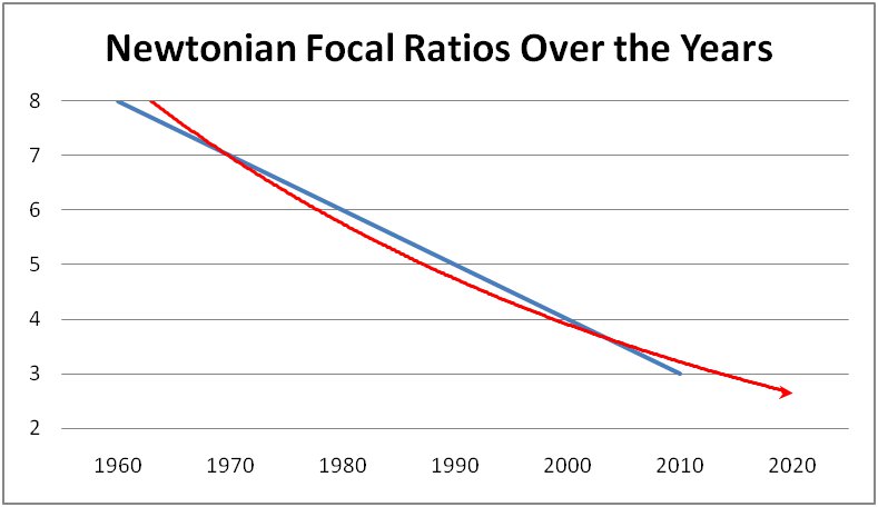
Perhaps surprisingly, the consensus fastest focal ratio has steadily decreased uniformly over the past 40 years. Most surprisingly, if the trend continues, we'll be at f/2.5 by the end of the decade!
Look at the growth of corrections in the eyepieces and their apparent fields of view:
Year - Eyepiece design
1960 - Huygens, Ramsden
1970 - Kellner, RKE
1980 - Plossl, Erfle, Orthoscopic
1990 - Coma corrector + Nagler
2000 - Radians
2010 - P2 coma corrector + Ethos
2020 - ???
F/3 telescopes are beginning to make their appearance, for instance, an f/3.3 telescope project is described in Miller and Wilson's Making and Enjoying Telescopes, published 1995. The breakthrough for me came when the French group, ADIA, built a 40 inch f/3.0 several years ago (see notable F3 scopes below). The accomplished, expert French telescope maker and observer, Frederic Gea, reported marvelous views and pinpoint images to the edge of the field of view, as long as a coma corrector was in place. I determined that I had to see for myself, and set about designing and building a new f/3.0 telescope. Recently Mike Lockwood, Steve Swayze, Kai Kretzschmar, among others, have made f/3.0; Lockwood ventured down to f/2.6. The reports are uniformly positive and exciting.

I built my 13.2 inch [34cm] F3 telescope because I wanted to explore F3 telescopes with the potential of building a much larger telescope that would not require a ladder to reach the eyepiece. I did not expect the rich and detailed views of low contrast wide angle objects. It is something to resolve two, even three NGC globular clusters in the same field of view into light sprinkles of star dust interwoven with the Milky Way's flowing tendrils of dark and light.
It has to do with the latest in eyepiece and coma corrector design.
Currently the widest apparent angle eyepieces on the market are TeleVue and Explore Scientific eyepieces with 100 degrees apparent field of view. The lowest power eyepiece in the TeleVue Ethos set is the 21mm. In the Explore Scientific 100 deg line it is the 25mm. The focal ratio that gives the widest field of view using this eyepiece is about F3 (assuming an eye that opens to 6mm exit pupil and a coma corrector that increases the focal ratio by 15%). This creates a huge "WOW" factor when viewing.
The image is expanded over a wider field resulting in more detail. There is larger aperture for the field of view meaning brighter stars and nebulae and more resolution.
Apparently not all focal ratios are created equally.
It's unlikely that monster 100 degree eyepieces will ever be commonly available in significantly longer focal lengths. Imagine such an eyepiece: it would be a foot long, several inches wide and weigh 20 pounds not to mention costing thousands of dollars. As the following table and images illustrate, there is a major difference in viewable field area between widest fields of view at various focal ratios.
Compare the Richest Field Telescope field of view and the focal ratio.
The old rule of thumb that telescopes with a range of focal ratios can achieve Richest Field performance as long as a suitably matched eyepiece is used is no longer valid. Eyepieces of extreme apparent field of view are now available, but only in shorter focal lengths.
Here's a table showing how eyepiece apparent field of view and focal length impact the RFT experience for varying focal ratios.
Table generated for aperture = 13 inches, exit pupil = 6mm. The telescope focal ratios optimized for several popular eyepieces.
| Telescope F.R. | Eyepiece | Coma corrector X | Eyepiece focal length mm | Apparent FOV deg | Telescope focal length inches | Eyepiece field stop mm | Actual FOV from field stop deg | Actual FOV from field stop + coma corrector deg | FOV area deg^2 | Mag |
| 2.5 | Ethos | 1.15 | 17 | 100 | 32 | 29.6 | 2.1 | 1.8 | 2.5 | 55 |
| 3.0 | Ethos | 1.15 | 21 | 100 | 40 | 36.2 | 2.1 | 1.8 | 2.5 | 55 |
| 3.6 | ES100 | 1.15 | 25 | 100 | 47 | 41 | 2.0 | 1.7 | 2.3 | 55 |
| 3.8 | Nagler | 1.15 | 26 | 82.0 | 49 | 35.0 | 1.6 | 1.4 | 1.5 | 55 |
| 5.2 | Nagler | 1 | 31 | 82.0 | 67 | 42.0 | 1.4 | 1.4 | 1.6 | 55 |
| 6.3 | OrionQ70 | 1 | 38 | 70.0 | 82 | 44.0 | 1.2 | 1.2 | 1.1 | 55 |
Notes on derivation:
Most columns are published values from the manufacturer.
The "Coma corrector X" is the magnification factor built into the coma corrector.
The exit pupil is the eyepiece's focal length divided by the focal ratio, further divided by the coma corrector magnification factor.
The "Actual FOV from Field Stop deg" is given by the formula: field stop in inches / focal length in inches * 57.3
There are three keys that work in concert:
1. Shorter eyepieces allow faster scopes to maintain 6mm exit pupil.
2. Wider apparent fields of eyepieces allow shorter eyepieces to achieve the same field stop as longer focal length eyepieces.
3. Since the field stops are essentially the same, the faster focal ratio results in a shorter telescope focal length which results in a larger field.
Here are the widest fields possible (each at 6mm exit pupil) for the above focal ratios through 13 inches aperture observing M31 (image from Stellarium):
|
F/2.5 - F/3.6 2.5 square deg field 100 deg Ethos/ES  |
F/3.8 - F/5.2 1.5 square deg field 82 deg Nagler  |
F/6.3 1.1 square deg field 70 deg wide field  |
Another interesting way to look at it is to calculate the maximum aperture possible for different focal ratios given a field of view. The focal ratios are optimized for widest angle eyepieces.
field of view = 1.8 deg, exit pupil = 6mm
| Telescope F.R. | Eyepiece | Eyepiece Focal Length mm | Apparent FOV deg | Eyepiece Field Stop mm | Coma corrector X | Max Mirror Diameter |
| 2.5 | Ethos | 17 | 100.0 | 29.6 | 1.15 | 13.1 |
| 3.0 | Ethos | 21 | 100.0 | 36.2 | 1.15 | 13.0 |
| 3.6 | ES100 | 25 | 100.0 | 41 | 1.15 | 12.2 |
| 3.8 | Nagler | 26 | 82.0 | 35.0 | 1.15 | 10.1 |
| 5.2 | Nagler | 31 | 82.0 | 42.0 | 1 | 10.2 |
| 6.3 | OrionQ70 | 38 | 70.0 | 44.0 | 1 | 8.7 |
Going down to f/3.6, f/3.0 or f/2.5 means jumping up in aperture from 10 inches to 13 inches. In other words, what we could see previously with 8 inch scopes and wide angle Erfle eyepieces in the 1960's to 1990's and with 10 inch scopes equipped with Naglers in the 1990's and 2000's is now seen with 13 inches aperture. This increase in aperture increases the limiting magnitude by a whole number.
Formula is: mirror diameter = eyepiece field stop * exit pupil * 57.3 / (true field of view * eyepiece focal length * 25.4)
From: true field of view = eyepiece field stop / telescope focal length * 57.3; focal length = focal ratio * mirror diameter; eyepiece focal length / exit pupil = focal ratio
I wrote a Newtonian telescope designer using this formula. With it I optimize for aperture, field of view and eye pupil in moments.
A New Relationship: Maximum Aperture or Field of View Based on Varying Focal Ratio While Holding Exit Pupil Constant
The impact of greater aperture for the same field of view is dramatic. Objects like the Horsehead, barely detectable in an 8 inch, are readily detectable in a 13 inch. Otherwise invisible galaxies pop into view. Instead of a faint object or two, many objects are visible at once.
However, for large thin mirrors to be made at f/3, something has to be done about the shrinking center thickness. A 40 inch diameter mirror at f/3 has a sagitta or central depth approaching an inch. That leaves precious little thickness at the center of the mirror. I determined to try a meniscus mirror, where the entire blank is curved to the appropriate shape by softening in a kiln, resulting in a mirror of constant thickness.
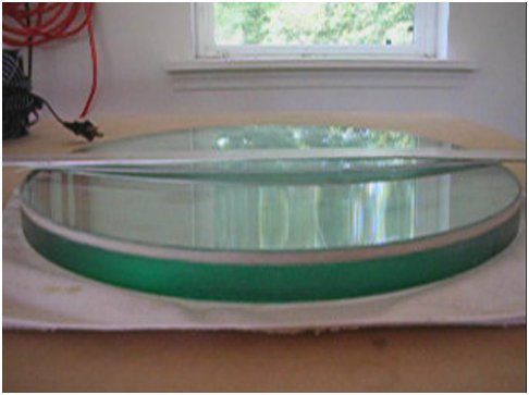
The meniscus mirror is a simple curved piece of glass with constant thickness from edge to center to edge. The meniscus shape is found in Maksutov telescopes and giant observatory mirrors like the Gemini 8.1 meter.
Unexpectedly, the nine point support I was envisioning wasn't needed; instead a simple three point back support and two point edge support supports the mirror without observable distortion.
A full thickness 12 inch or even a thinner 13 inch mirror requires a 9 pt support. Deformation is clearly seen in the star test if a 3 pt support is used. And high power images are heavily compromised in very thin 12 inch mirrors made from flat glass. Not a trace of deformation can be seen at highest powers in the star test with the 13 inch meniscus mirror on a 3 pt support. I've had other experienced mirror makers confirm the star test results.
Meniscus mirrors are lightweight because the curved glass is relatively thin. For the same center thickness, a meniscus mirror is lighter than a conventional mirror with a flat back.
The thin plate glass cools quickly in minutes. I don't need a fan while observing. Taking the scope outside requires about a 15 minute cool down period, after which the star images are very stable. Since the glass is thin and I have a fan for backup, I can substitute inexpensive plate glass. Plate glass runs 20x cheaper than Pyrex. The downside is that when making your own mirrors, plate glass is a a pain during figuring because care must be taken to ensure that the glass is in equilibrium with its ambient surroundings. It's necessary to take active steps to equilibrate the mirror. I use fans blowing air in an insulated room on the mirror during the indoor star test. Thanks to active mirror cooling and an insulated shop, I can do a half dozen figuring sessions each evening.
Surprisingly, taking the mirror from the warm shop to star testing in the cold night air does not lead to strong overcorrection. There's a bit or turned edge for a few minutes, then the mirror settles down and gives a great star test at high power and sharp planetary images.
It's been a sine qua non understanding that mirrors look overcorrected when cooling. The consistent explanation extending back centuries is that the front surface of the glass, exposed to the night air and dark sky, cools and shrinks, pinching the mirror's paraboloidal shape. Allyn Thompson in his 1947 book, "Making Your Own Telescope", conducted a series of experiments, measuring the over-correction of a mirror heated above ambient temperature using a knife-edge.He concludes that temperature difference of only a few degrees will ruin the mirror's paraboloidal shape.
The outstanding characteristic of my meniscus mirrors is the thinness. The glass cools quickly all the way through to its backside. Cooling through the mirror's edge affects only the extreme outer zone (glass interior to the extreme edge is cooled by the adjacent front and back surfaces), causing the observed transient turned down edge.
Finally, meniscus mirrors avoid the headache that comes from thin mirrors with deep curves that vary drastically in thickness from center to edge. The edge in these mirrors lag behind the center in keeping up with the drop in nighttime temperatures as the night progresses.
In a sense, computer controlled kilns promise to be an enabling technology, allowing thin mirrors to be slumped to very large diameters, no longer being limited to sheet Pyrex's width of 40 inches or so. Instead of grinding a curve into the mirror's face, the mirror is placed upside over a convex mold and heated until the glass softens and folds down over the mold. The kiln is then directed by computer control through the annealing cycle, cooling the glass over a period of several days. The cost of a kiln plus plate glass is competitive with a Pyrex sheet glass blank, with the bonus that the kiln can be used again.
Part of my interest in the 13 inch f/3 was to see how difficult grinding an f/3 mirror truly is. Well, I can report that it is fundamentally no different than grinding any other mirror, except that more parabolization is pushed into a smaller aperture and the error tolerance tightens a bit. I used standard mirror making techniques with excellent results. I gage the difficulty of the 13 inch f/3 to be roughly equal to the difficulty of grinding a 20 inch f/5. Curiously, the 13 inch f/3 has about the same degree of parabolization as the 20 inch f/5. So if you can make a somewhat larger mirror, then you can be confident in attempting a somewhat smaller f/3 mirror.
My goal in grinding, polishing and figuring a mirror is to make it indistinguishable from perfect. Consequently, I most need mirror tests that qualitatively reveal defects. I have less of a need for quantitative tests that yield numbers because I don't really care if the error is 1/8 wave or 1/8.5 wave. The error has to be removed. A key question in my mind was, "Could I detect minuscule deviations that could prove injurious at high magnifications given the ultra-fast F3 focal ratio?"
I used the Ronchi matching bands test along with the indoor star test. The Ronchi test proved quite sensitive, able to show the slightest zonal defects and overall paraboloidal shape. I conducted indoor star tests using my 20 inch F5 mirror, a proven highest quality optic that gives a perfect star test at highest magnifications. I used a fine point needle and make several pinholes of varying size in aluminum foil placed against an aluminum block. The foil then went into the focuser, placed at the center of the focal plane, along with a bright light above it. The 13 inch mirror in its wooden test frame along with diagonal, focuser and high power eyepiece was aimed horizontally into the 20 inch, also placed horizontally. Since my shop is insulated, the air was very stable and I was able to conduct high quality star tests. The varying pinholes provided artificial stars of different brightness and size. A final check with the outdoor star test of several hours of careful back and forth focusing at high power with the 13 inch in its test frame aimed at Polaris confirmed my test approach.
I quickly realized that such a short telescope called for a new telescope mounting design: the incredibly stubby truss tubes as commonly built begged to be replaced. It's important when considering the patterns of telescope design to allow the design to grow organically. If one component varies from tradition, then it is likely that surrounding components will also.
An f/3 with a lightweight mirror places the center of gravity farther up the tube than what is customary. This results in benefits such as balance insensitivity, small footprint, and a smaller eyepiece swing from horizon to vertical.
Balance insensitivity means the telescope can move smoothly in altitude despite today's heavy eyepieces: no counter-weighting need apply here. Small footprint means that the scope rotates in azimuth within the smallest possible circle. This has particular impact on observatories, which can be horrendously large with Dobs that balance close to the rear. For instance, a 16 inch Dob might need a roll-off roof observatory 12 feet x 12 feet. By moving the center of gravity to the mid-point of the optical tube assembly, the building size can be greatly reduced. Roll off roof observatories are so much easier to build when the roof size is small. Minimizing eyepiece swing means that I can observe with the 13 inch sitting in a chair regardless of whether the scope is pointed at the horizon or is pointed vertical.
It's my observation that assembly time and difficulty has a large impact on how often the scope is used. It's not so much how fast a scope could be assembled. Instead, it's more of, "Do I have the energy tonight to drive somewhere and set it up?" The key is to avoid assembling the scope at all.
I designed my first folding scope, the 'Tri-Dob', in 2001. It featured folding altitude rims. I wanted more though, to fold the entire telescope such that it would fold for transport and unfold for observing like Origami. I studied a number of folding arrangements, which essentially squeeze air out of the telescope as it folds up. Folding is much quicker and most importantly, easier than assembling. In the end I chose a three-fold arrangement that squeezes the telescope into a small cube, easily picked up and carried by hand (total weight is about 25 pounds). From the bottom up, the folds are 30 degrees, 42 degrees, and 108 degrees. Note that the folds add up to 180 degrees, which results in the upper end folded down against the primary mirror, about as compact as possible.
Google Sketchup model is available from the online repository here...
More on folding and sliding telescopes can be found here...
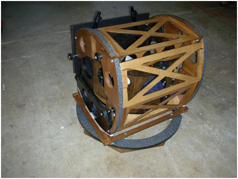
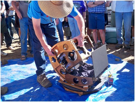
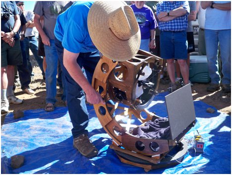
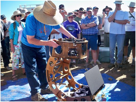
Unfolding the telescope at the Oregon Star Party Telescope Walkabout, 2010
I improved the design with a follow-on second generation iteration. There is one fewer fold and the folded volume is 1/3 less than the first generation model. I use folding upper trusses made from ApplyPly; as is all the wood on the telescope. They are held in position by the mirror cover that doubles as a dew shield. This is proving very rigid, though the telescope could survive without the upper trusses because of the folding altitude rim engineering. Other notable features include a return to the single upper ring that I first began building in the early 1990's and a very light flex rocker with centerless bearings. Diagonal size continues to be a 3.1 inch [78mm]. The Google Sketchup model is available here...
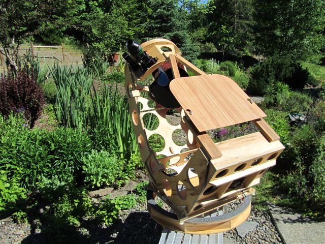
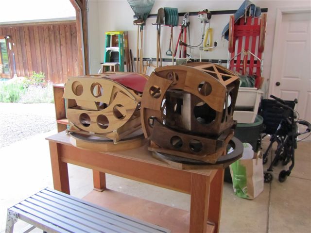
Compare to the first iteration design: the new more compact design is on the left.
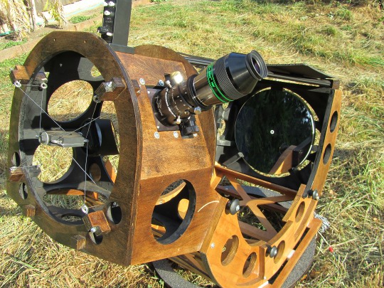
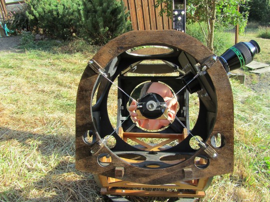
I always look for ways to create telescope components that serve multiple purposes. With the center of gravity in the middle calling for sweeping altitude bearings, it occurred to me that the reinforced altitude bearings can take the place of most of the truss tubes, and provide folding pivots to boot. This works quite nicely in practice the telescope is rock solid with no hint of any vibration.
I use two tests to determine the design integrity of the optical tube assembly. First is the optical alignment test: can alignment be maintained exactly as the scope swings between horizontal and vertical? Finally, can I grab the upper end and twist the mirror end out of the rocker? This design passes both tests with flying colors.
You might note the wire spider. I've been using wire spiders for many years. They work wonderfully in that there's no diffraction except short spikes around the brightest stars and the diagonal stays rock solid and unmoved, allowing perfect optical alignment from horizon to zenith. Curiously and counter intuitively, I discovered that the tension in the wires is irrelevant to supporting the diagonal properly. Mathematical analysis reveals that tension drops from the picture. Further, wire spiders have less springiness than traditional spiders, particularly when rotating the diagonal holder back and forth. On very large scopes, wind blowing through the upper end can create a never-ending vibration of the diagonal, visible as astigmatism at high power. Properly designed, both traditional and wire spiders need not suffer this ailment. The key is to break apart the spider at the hub into two separate sections like '>-<', separated by a hub that holds the diagonal holder. Consequently, stability and resistance to flexure and twist is determined by the geometry of the wires. Hence my wires cross in broad 'X's with the two 'V's on either side of the hub. The wire spider is a single piece of wire, wired into position by supporting the hub on a removable jig. You can see the drilled holes that hold the jig in position at the top of the upper end. Once the wire is strung into position, I tighten the eye bolts until there is no slop in the wire then remove the jig.
Focusing range is a little discussed topic amongst amateurs. However, it is a primary factor determining how sharp is the image. Focusing range is the distance that the focuser can be moved on either side of the theoretically perfect focus yet not change the image sharpness.
The formula for focus range where the optical path difference is limited to quarter wave is: focus range = wavelength of light / index of refraction times the sin squared of the angle of the edge ray (focus range = λ /N' sin^2 U'). This simplifies to 0.0001 * focal ratio squared. See Conrady's Applied Optics and Optical Design, volume 1, pages 136-7.
While a F5 scope has a focus range of 0.002, a F3 scope has a much tighter focus range of 0.001. Best procedure is to obtain the ultra finest focuser, then carefully focus back and forth, stopping in the middle. If dissatisfied, repeat. The difference at F3 is between a so-so Saturn and a great Saturn.
Here are (unexpected) lessons learned from designing and building a very short focal ratio telescope.
Views through the telescope are wonderful. Incredibly wide fields at low power with pinpoint stars to the edge give way to high power views with excellent resolution and contrast. Dark nebulae have never looked better, showcase objects are wonderfully framed and globular clusters are resolved into tiny pinpoints of starlight at magnification. Here are early observations, images representing the field of view through the 13 inch from Microsoft's WWT. Keep in mind that these fields of view are with a 13 inch telescope!
 |
M31: spectacular aggregate view: entire galaxy along with companions fit into the field of view; striking multiple dust lanes; details in galaxy arms at the extensions and in the companions |  |
Horsehead, Flame nebulae: in one view the Horsehead is faintly visible (no filter) with good detail in the Flame nebula; NGC 2023 and IC 435 are bright; all this despite a very bright Zeta Orionis |
 |
Pleiades: all of the extremely bright stars fit into a single view; extensive nebulosity everywhere, particularly detailed next to Alcyone with extensive sweeping from Merope to edge of view, along with some of the general nebulosity that surrounds the Pleiades |  |
M42 region: entire loop of M42 seen with lots of detail with some color; the green nebulosity embedding the Trapezium is quite striking, field of view extends from the open cluster NGC 1981 through NGC 1973/5/7 up past NGC 1980. |
 |
Markarian's Chain, the Virgo Cluster, M84-M86 area. The image is a good match to the view through the eyepiece (though the stars are missing) |  |
Lagoon and Trifid nebulae both fit into the same field of view, but with 13 inches aperture. Very nice! |
Mark Christensen sent this image of the Small Sagittarius Star Cloud taken with his 6 inch f/2.7. It illustrates the stunning tack sharp field possible with super fast scopes.

For more on f/3 observing experiences, check out Frederic Gae et al large f/3 telescopes along with Lockwood's observations. Run, don't walk to your nearest f/3 telescope, clear your mind of preconceptions and find out for yourself!
| Design Aspect | Pluses | Minuses |
| F3 | Wider field at lowest magnification (Richest Field) compared to f/4 and slower: excels at very low contrast difficult objects, excellent at high power - pinpoint images. | Coma corrector required (with TeleVue P2 coma corrector, the coma is equivalent to that of an F/12, so better than standard Dob). There is no vignetting - see my comments above. |
| "No ladder" eyepiece height | Primary mirror takes extra skill to produce | |
| Telescope weighs less | Not every eyepiece may perform well | |
| Shorter stiffer tube assembly holds optical alignment (collimation) better | Purchase additional eyepieces | |
| Diagonal size same as f/4.5 scopes due to flatter field illumination profile | Optical alignment (collimation) tolerance is 0.2 mm | |
| Ultimate star hopping telescope with its extra wide field of view | Focusing is very touchy at small exit pupils/high magnifications: need a precision focuser that resolves to better than 1/1000 inch. Focusing is probably the greatest practical disadvantage in the field. | |
| Shorter tube with Center of Gravity mid-range | Much smaller observatory footprint | |
| Less eyepiece swing from horizontal to vertical | ||
| No need to counterweight heavy eyepieces | ||
| Meniscus mirror shape | Meniscus shape and less weight means simpler mirror cell | |
| Thinner meniscus shape equilibrates quicker and shows no overcorrection during evening observing while temperature drops rapidly. | ||
| Folding design | Compact travel profile |
Difficult to design folds so that there are no collisions |
| Setup time in seconds | Precision construction required | |
| Lighter weight | ||
| Wire spider | Less diffraction than standard spiders | Need jig for initial assembly |
| Inexpensive: a few dollars for the wire | ||
| Stronger than standard spiders because of the wider geometry |