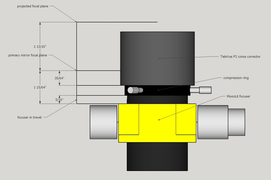
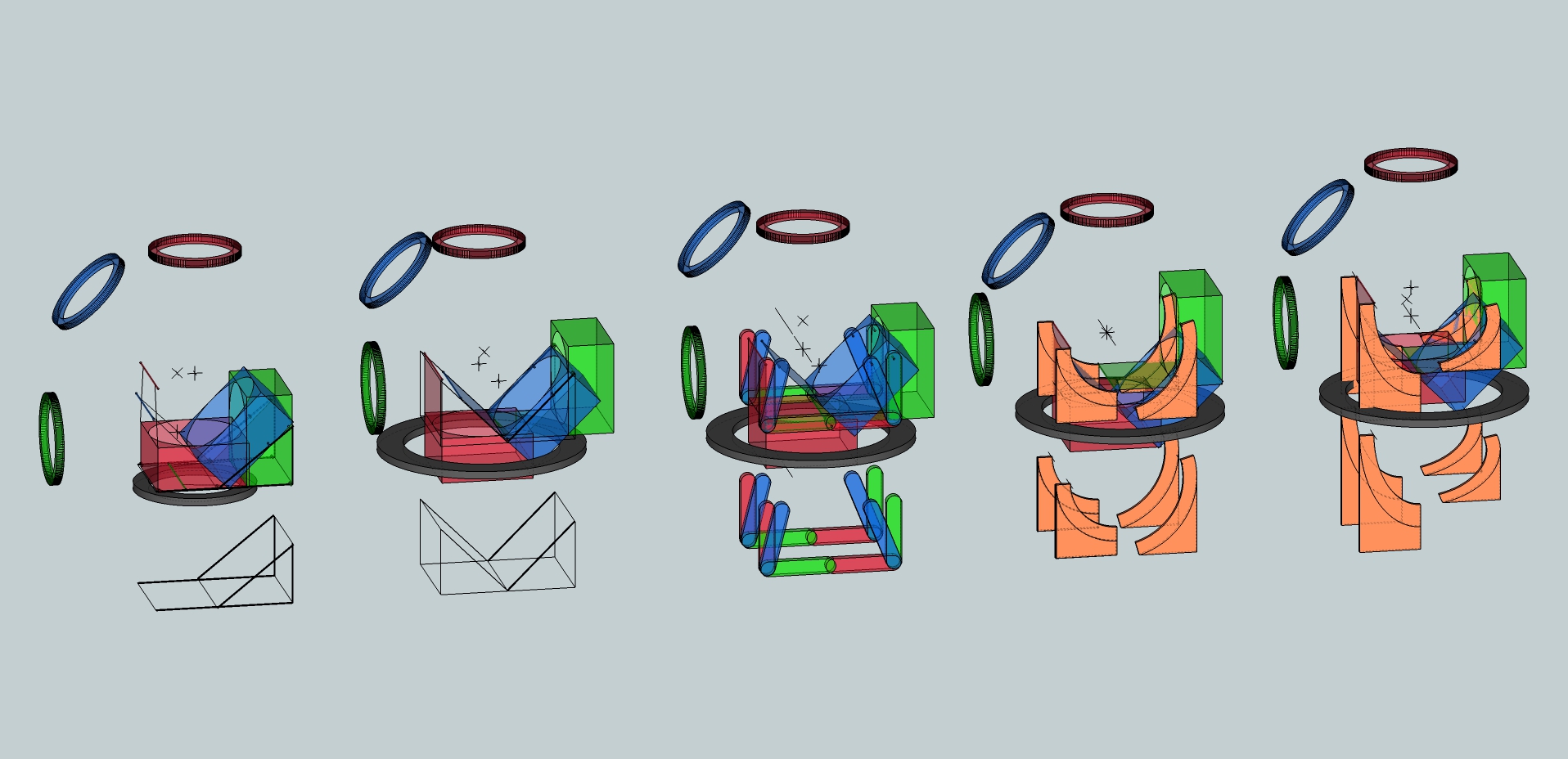
Placing the focuser can be confusing with a coma corrector. I have used this layout on four scopes.
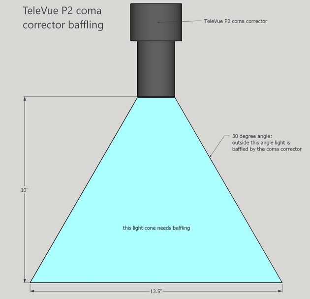
Baffling can be confusing because the coma corrector changes the focal plane placement. Empirically I found that the coma corrector blocks intrusive light up to 30 degrees off-axis.
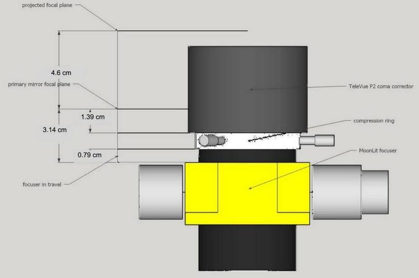

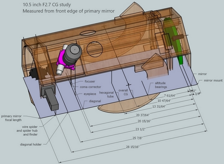
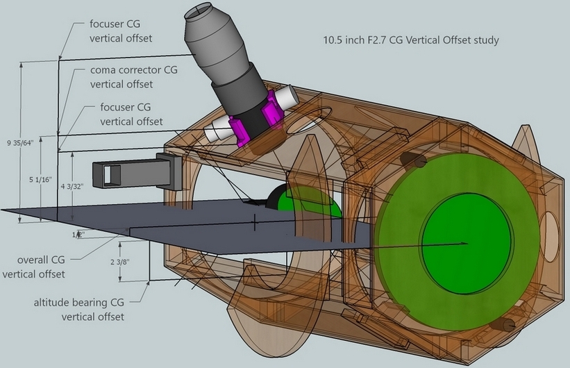
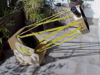
Metric images courtesy Berthold Hamburger.
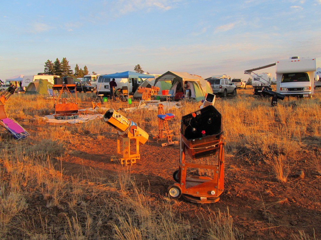
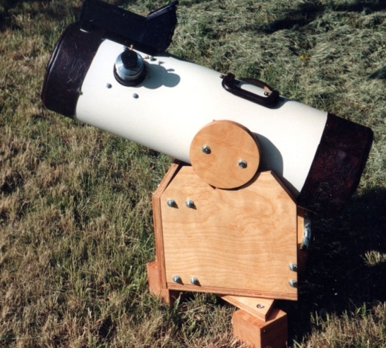
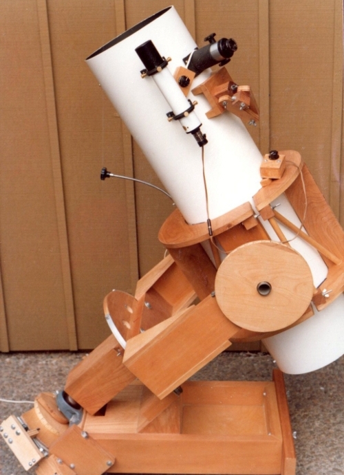
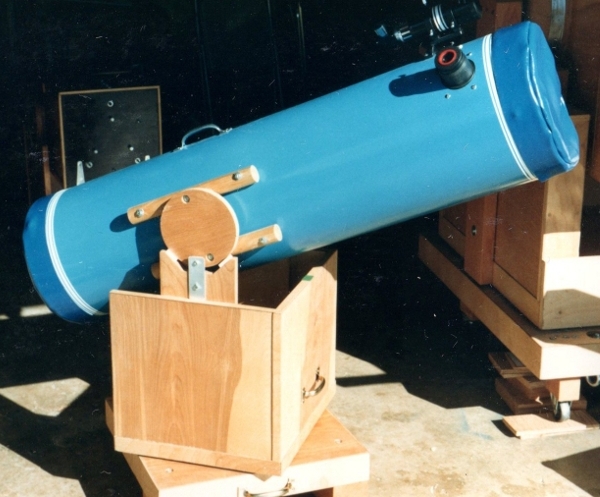
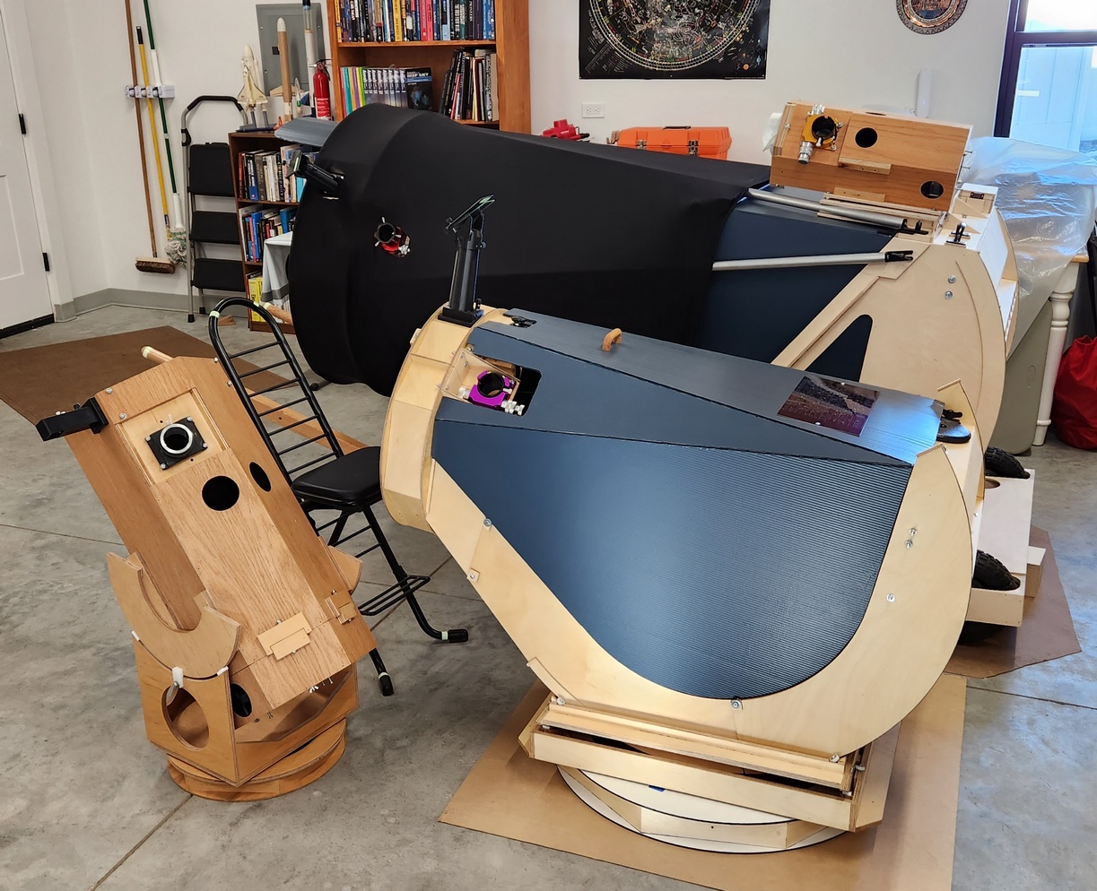
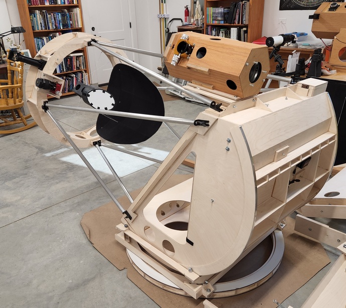
My 10 inch F5 fork, 14.25 inch F5 horseshoe, 20.5 inch F5 TriDob and 25 inch F2.6 3-axis mount.
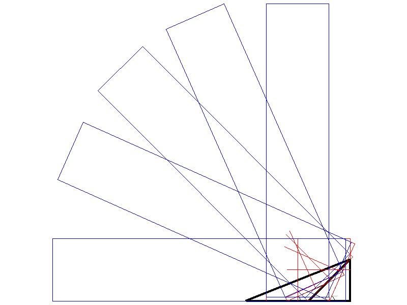
The Equatorial table designer draws tables with either two sectors and a polar pivot, or four sectors. The sectors can be shaped vertically if desired.
The history of the visual telescope is recorded in the march of better views through the eyepiece. I dream that the best views are yet to be seen. Revolutions in telescope design are driven by dreamers.
The artisan nature of building a telescope with one's own hands is deeply satisfying. Shaping the telescope's mirror by hand is deeply satisfying. Observing by sketching by hand what we perceive through the eyepiece is sublime. The abstract nature of telescope design with all it's permutations is astonishing. However the math and calculations can be complex. Consequently I wrote online calculators to optimize my telescope designs. I include investigations and articles. Smart telescopes are the culmination of technology. With the press of button or two, they will emit a processed finished image. However, this incredibly convenient technology comes at the cost of abandoning artisan skills, of working with our hands.
I created 'NewtDesigner', a series of calculators, articles and investigations, not only to help me become a better artisan, but also to investigate telescope design. For example, how to optimize a F6 scope for low magnification wide angle viewing? How to design a fabulously fast telescope where the optimization hangs on a narrow precipice.
Perhaps you'll find 'NewtDesigner' useful too. For the mirror making side, see my Joy of Mirror Making.
Results:
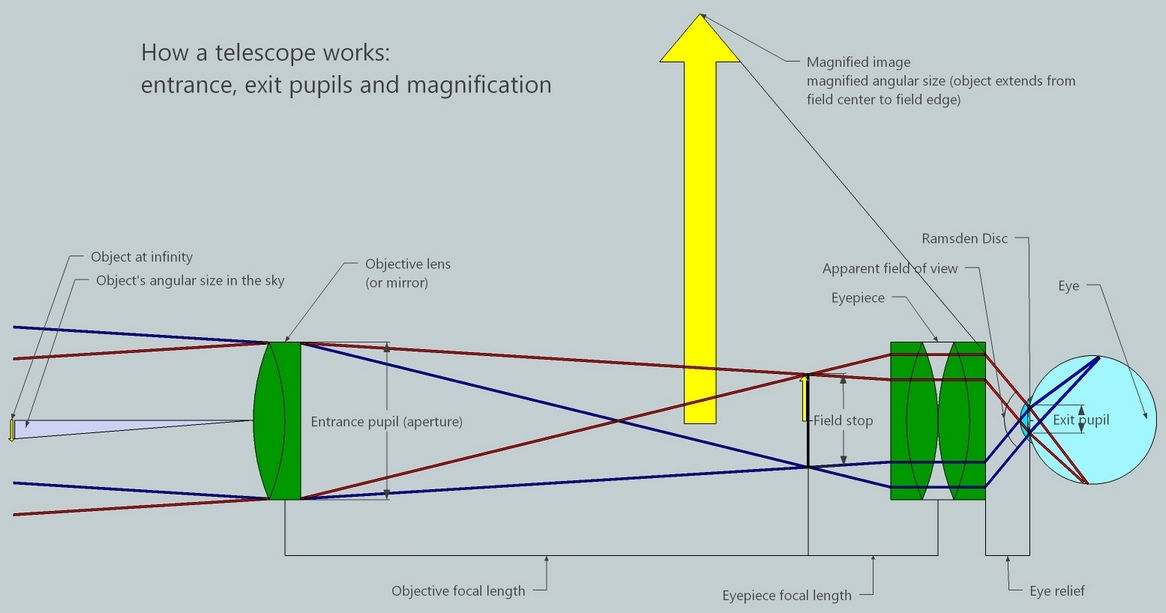
A telescope has two 'powers'.
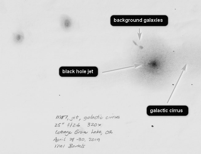
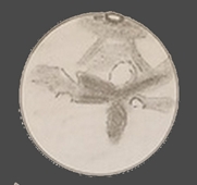
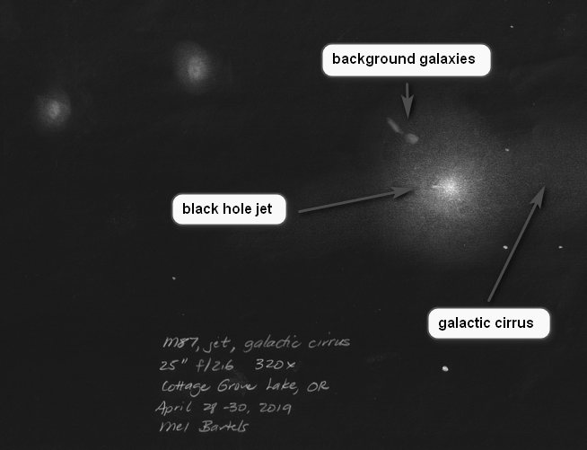
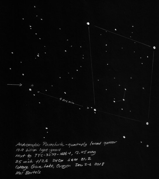
Here are three examples. The first is Mars as seen through a 8 inch telescope. The second is the black hole jet of Messier 87, a giant elliptical galaxy in the Virgo Cluster. In a large telescope the jet is magnified, resolved and brightened sufficiently to be seen. The third, the so-called "Andromeda's Parachute" is a multiply lensed quaser that looks like a parachute or umbrella. The light left the quaser 10.9 billion years ago. This is the most distant object I have observed visually.
The invention of the telescope opened up a vast unseen universe, advancing scientific and technological knowledge, creating new fields of inquiry and discovery. Understanding how a telescope works not only astonishes us but also helps us design better scopes.
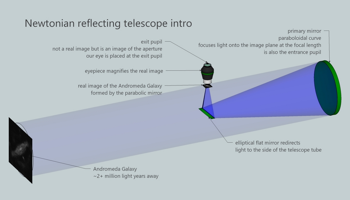
Newtonian reflector intro notes
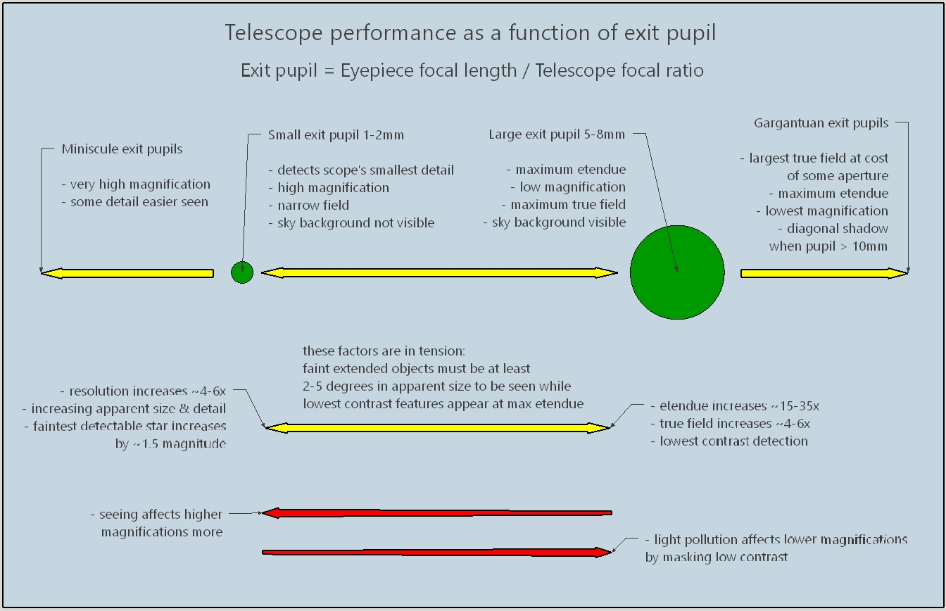
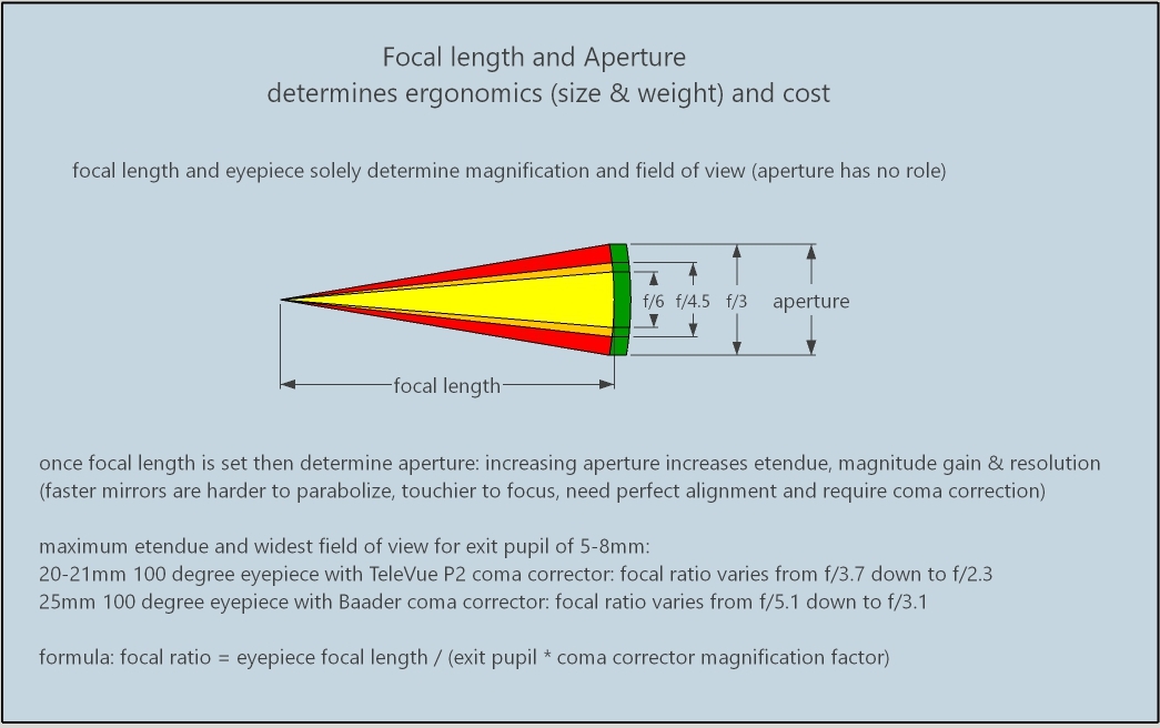
There are two diagrams to understand: telescope performance as a function of exit pupil, and, focal length and aperture. Then follows a series of explanatory topics.
The telescope has two pupils:
The exit pupil is calculated from:
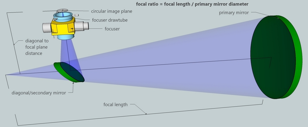
Focal ratio is the speed of the telescope and is found by diving the focal length by the mirror diameter.
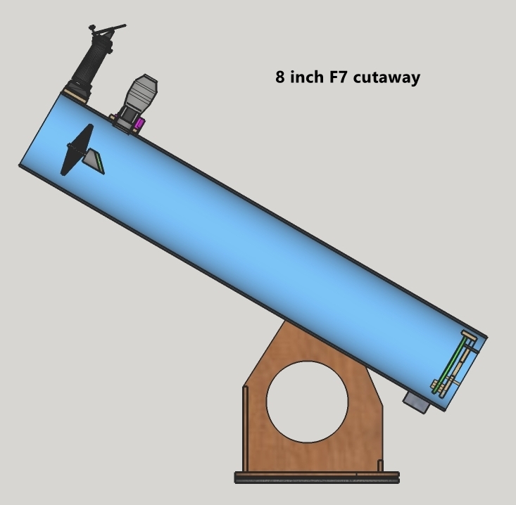
8 inch F7
 10 inch F5
 16 inch F2.9
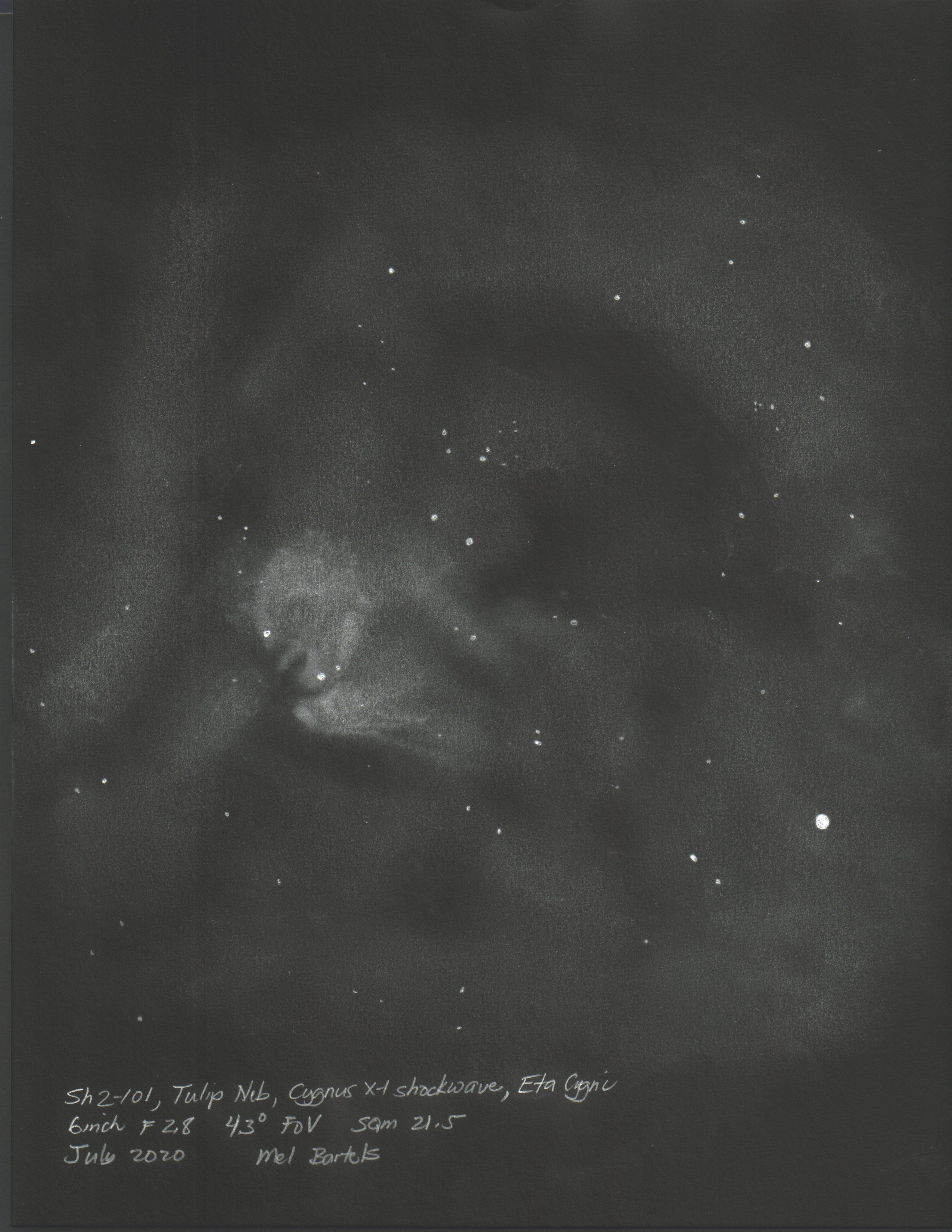
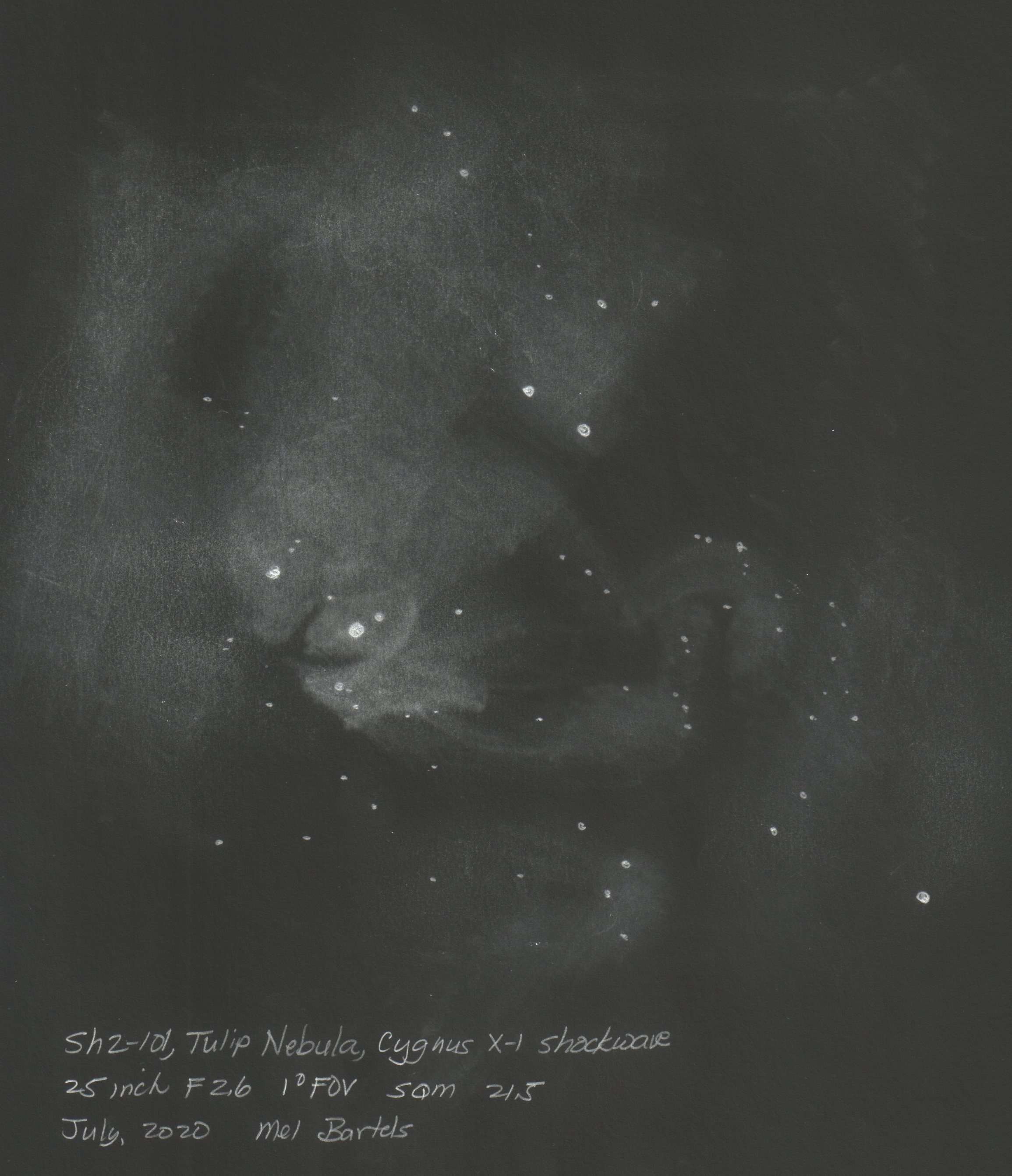
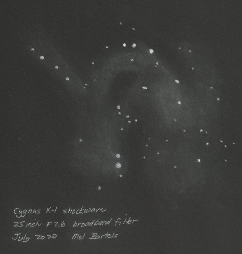
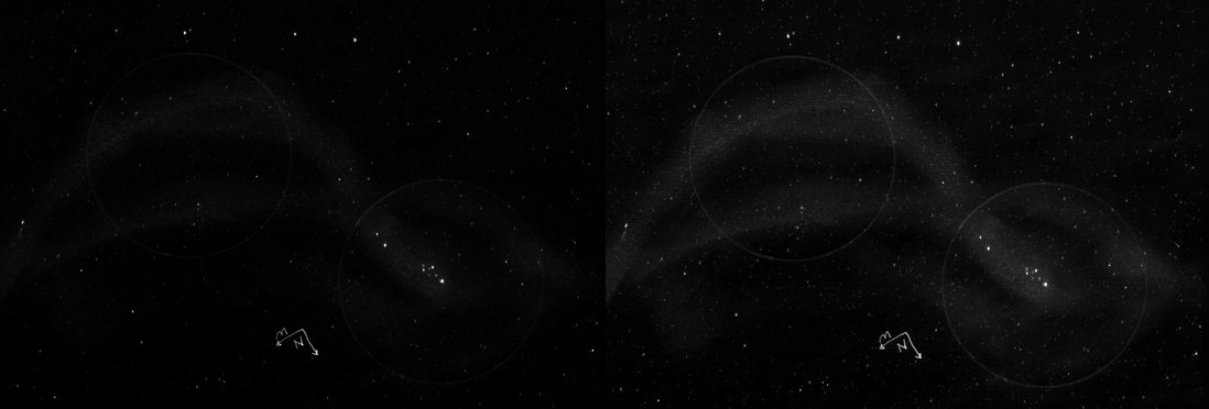
For example, three views of the Cygnus X-1 shockwave illustrating wide to narrow true fields of view.
Select eyepiece
Use a coma corrector?
select
magnification factor
Limit eye pupil (mm) to
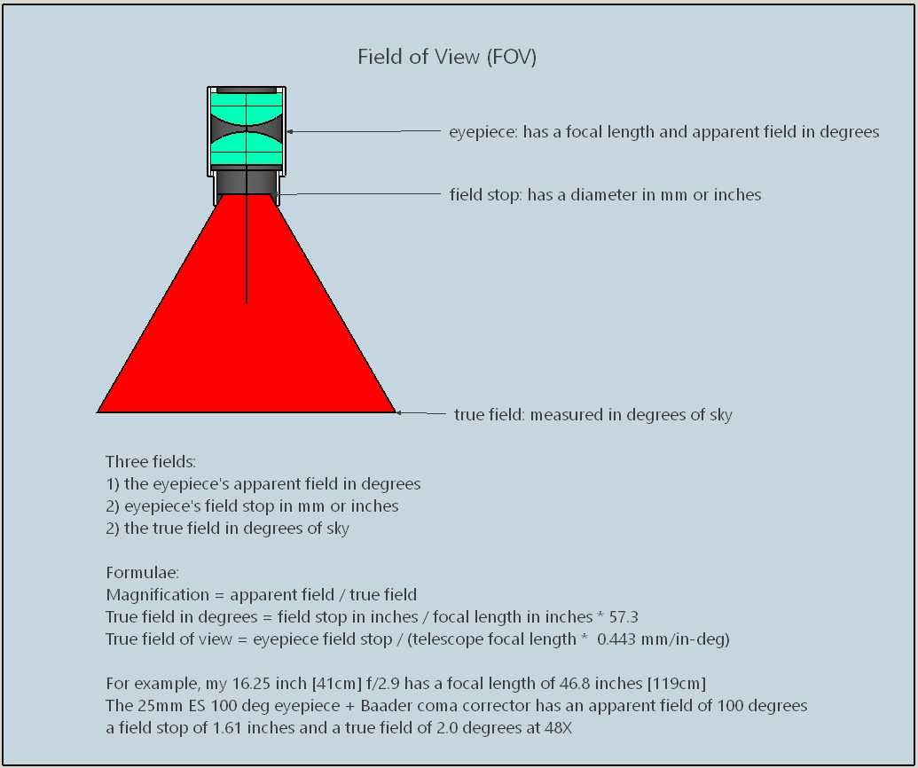
True field of view (deg)
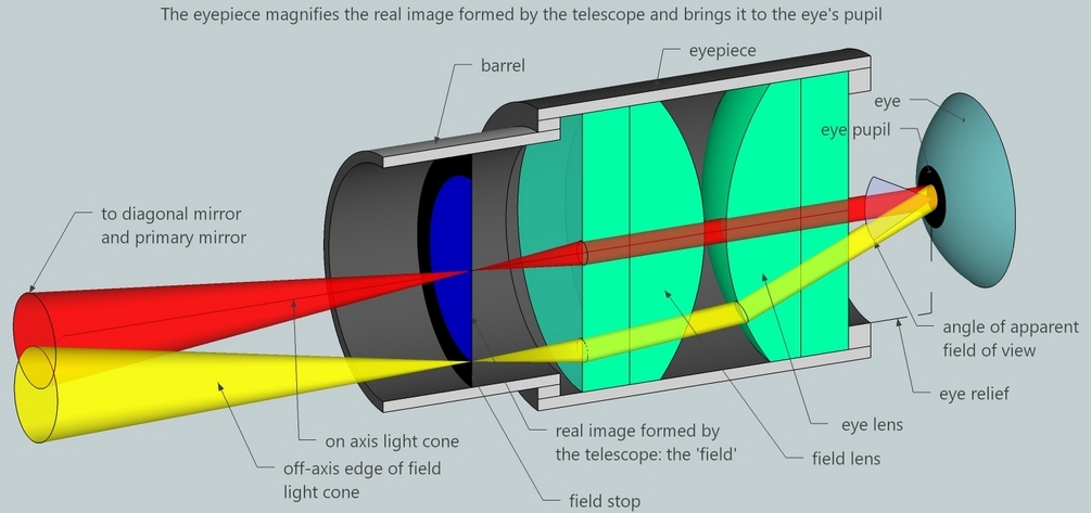
Light rays can be traced through the telescope.
The eye's background noise is on the order of 25 to 26 magnitudes per square arc-second.
The dark adapted eye detects 6-10 photons; in certain situations the eye can detect a single photon.
An eye contains 90 million rods. Two to three degrees apparent size involves 25,000 adjacent rods. The brain becomes can become conscious that these rods are signalling at a higher level than the surrounding forest of rods. These specs are not that dissimilar to digital cameras: the eye-brain is an amazing detector.
The Law Of Etendue says that the surface brightness of an object in the eye cannot exceed that of the object in the sky. However, etendue can be reduced by increasing magnification which shrinks the telescope's exit pupil. An exit pupil of 3.5mm as compared to 7mm reduces the object's surface brightness by 0.75 magnitude, rendering invisible very faint objects no brighter than the eye's background noise.
Filtered views such as OIII and HBeta filters make the sky background fainter increasing detectable contrast.
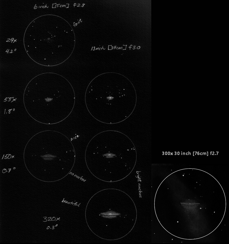
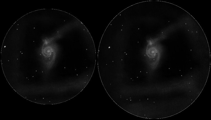
As the magnification increases going from maximum exit pupil to minimum exit pupil, how does the eye respond? We can see from the following drawings, that for smaller scale objects like M104, a galaxy in the Virgo Cluster, the eye hangs onto faint nebulosity surprisingly well (though the faintest nebulosity is no longer visible) while the increasing resolution makes for a beautiful view.
Rayleigh's resolution criteria (in radians) = wavelength of light / mirror diameter. Commonsense suggests that an aperture can resolve it's diameter. For example, a mirror with diameter of one wave should be able resolve one wave. Using this formula, a 6 inch mirror resolves 1.3 arc-seconds (there are approximately 273,000 lightwaves across the 6 inch diameter and approximately 206,000 arc-seconds in a radian, the ratio being 1.3). See the mathematical formula section in the Wikipedia page on the Airy disk. However, in the case of equally bright double stars, it is possible to squeeze the two Airy disks closer together. Dawe found empirically that double star resolution for a 6 inch mirror is closer to 0.8 arc-seconds, about a third closer. Dawe's formula (in arc-seconds) is 4.56 / mirror diameter (in inches).
What magnification and exit pupil do we need then, with a 6 inch telescope? Empirically we know that amateurs with our bare eyes can resolve 1 arc-minute. The difference between 1 arc-minute and 1 arc-second is 60x. A 6inch at 60x produces a 2.5mm exit pupil.
Spacing between the eye's rod cells, used in night vision, suggest a similar resolution.
Another perspective is to find the intersection between reducing aberrations of the eye (worse at large pupils) and the eye's ability to resolve stars' diffraction (least at large pupils). This intersection occurs at an exit pupil of about 3.5mm. This pupil produces the tightest diameter stellar image and the brightest stellar image.
Higher magnifications make sufficiently bright objects easier to see, including close double stars. Smaller aperture scopes can profit from higher magnifications; larger apertures not so much, thanks to seeing.
Why should I care?
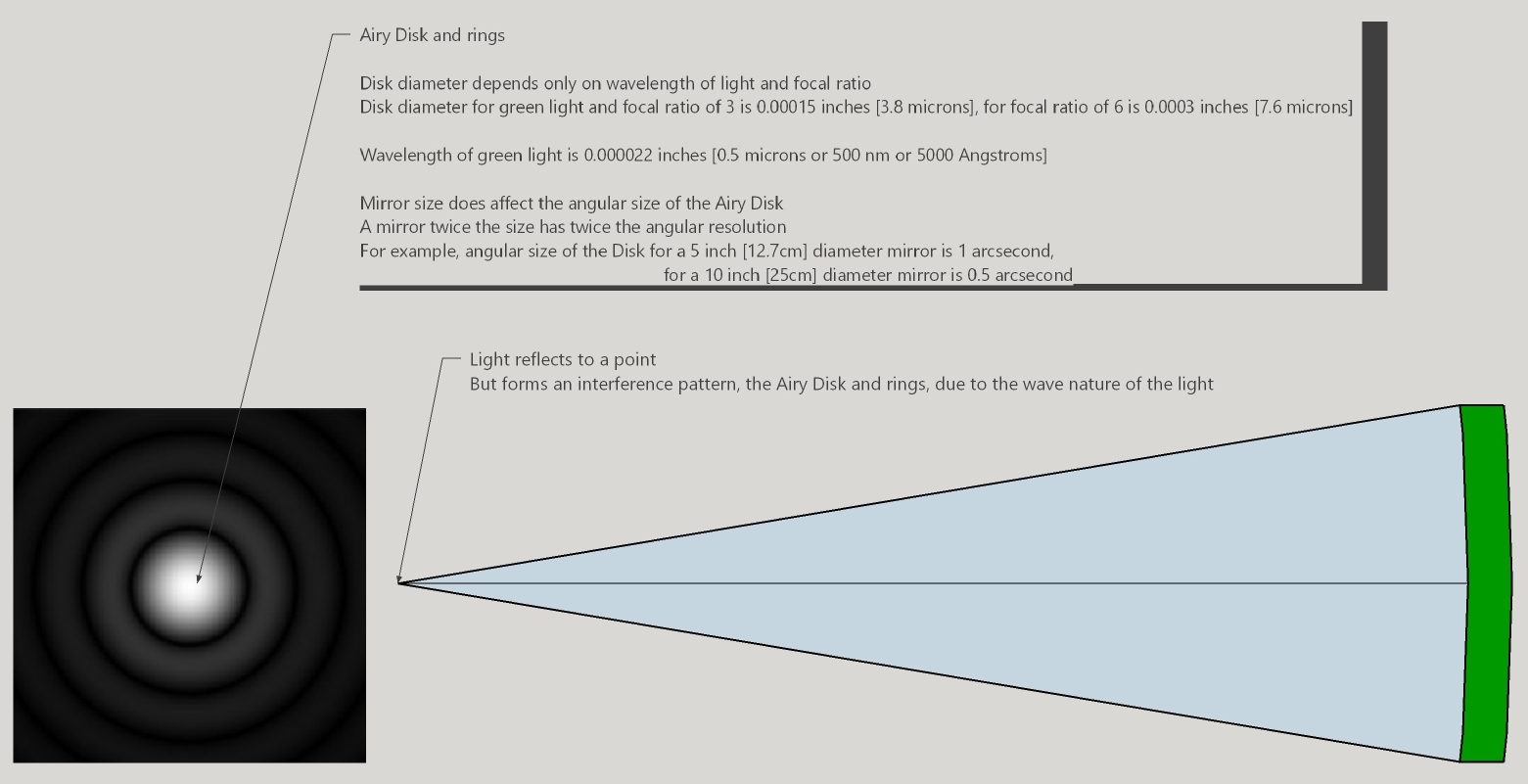
What is the Airy disk? The smallest spot of light that a perfect lens or mirror can focus is called the Airy disk. Light going through a circular opening forms a spot of light surrounded by ever fainter rings.
Why a discrete spot size and rings? Light diffracts because it has wave properties. Think of the famous slit experiment where light or electrons, anything that has wave properties travel through a slit. Projected on the wall will be a fuzzy image of the slit (the equivalent of the Airy disk), surrounded with ever fainter straight bands. Make the slit a circular opening and now the fuzzy image of the slit becomes a fuzzy disk surrounded by ever fainter rings.
What is the size of the Airy disk? There are two ways to measure the Airy disk. The first is the linear size as if we had an incredibly precise ruler. For green light, the diameter is 0.00124 mm times the focal ratio. For example, an F8 scope has an Airy disk diameter of 0.00124*8=0.01 mm. In inches it is 0.00005 times the focal ratio. For example, an F8 scope has an Airy disk diameter of 0.00005*8= 0.0004 inches.
The second is measuring the angular diameter of the Airy disk. For green light, the diameter of the Airy disk in arc seconds is 260 divided by the lens or mirror diameter in millimeters. For example, the Airy disk’s angular size for a 150mm diameter lens or mirror is 260/150= 1.8 arc-seconds. In inches it is 11 divided by the lens or mirror diameter in inches. For example, the Airy disk’s angular size for a 6 inch diameter lens or mirror is 11/6= 1.7 arc-seconds.
How can it be that the linear size of the Airy disk depends only on the focal ratio? Because that's what remains when the math terms cancel. But why is that? Let's make up the following example.
Scope 'A' is a 6 inch [15cm] F8,
scope 'B' is a 12 inch [30cm] F4,
scope 'C' is a 6 inch [15cm] F4.
Scopes 'A' and 'B' have the same focal length,
scopes 'A' and 'C' have the same aperture,
scopes 'B' and 'C' have the same focal ratio.
Scope 'B', with twice the aperture resolves twice that of scope 'A' so the Airy disk is half the size of scope 'A'.
Scope 'C' with the same aperture of scope 'A' resolves the same but with half the focal length, the Airy disk diameter is half the size. So I see that the Airy disk diameter depends solely on the focal ratio where faster focal ratios result in smaller Airy disk diameters.
Scope 'B' resolves twice that of scope 'C' but with twice the focal length the Airy disk ends up the same linear size.
How does resolution relate to the Airy disk? Resolution is typically taken as half the Airy disk. For a 15cm, 6 inch lens or mirror, the resolution is 0.8 arc-seconds.
Why is the size of the Airy disk important? If I am an imager, then I want to match my camera’s resolution to the telescope’s resolution. I’ll alter the camera or telescope to make the match. If I am a visual observer, then I want to know the resolution limit of my telescope. Visually I will select eyepieces that allow my eye to resolve the telescope’s theoretical resolution limit.
How does the Airy disk play into mirror making? For a smooth mirror the optician wants all the geometric light rays to pass through the Airy disk. The optician needs to know the size of the Airy disk when testing with an artificial star or say the Foucault test.
Who was George Biddell Airy? Sir Airy was an English astronomer and mathematician who became Astronomer Royal, reorganizing the national observatory. He’s famous for many accomplishments including establishing the prime meridian and measuring the density of the Earth. In 1831 he described diffraction of circular apertures and a complete theory of the rainbow. He also discovered the 243 year Venus cycle. Controversially he is blamed for losing the race to discover Neptune to the French.
Here are two questions for you to ponder.
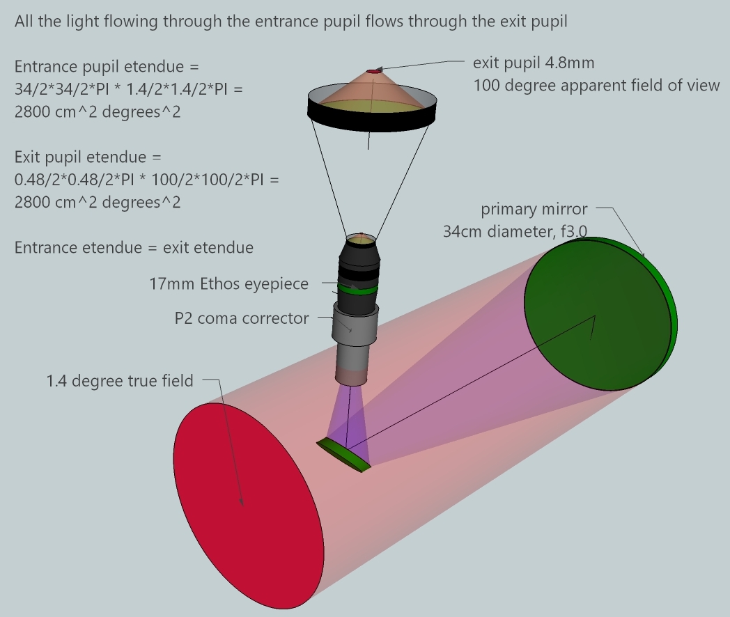
Etendue is a French word meaning optical throughput, that is, the amount of light flowing through a telescope. Light enters the telescope through the entrance pupil or stop and leaves the telescope through the exit pupil or stop. The exit pupil is an image of the entrance pupil, in our case, the primary mirror. Light can also flow backwards, from the exit pupil to the entrance pupil.
Etendue is calculated either as the aperture's area times the solid angle area of the true field or the exit pupil times the solid angle area of the eyepiece's apparent field of view. The cone of light entering the telescope is shallow and broad: 1.4 degrees cone with a 34cm opening. The cone of light exiting a telescope is steep and narrow: a 100 degree cone with a 4.8mm opening. The ratio of the entrance come to the exit cone, 100 deg / 1.4 deg, is 71x. The ratio of the aperture to the exit pupil, 34cm / 0.48cm is the same ratio, 71x. The magnification of the telescope and eyepiece is the same 71x.
Etendue can be increased by
All light rays entering the scope leave the scope. They are neither increased nor decreased (except for the insignificant losses due to imperfect reflection, absorption in glass, reflected from glass surfaces and occasionally filtered). Indeed, this is a law of nature.
The Law of Conservation of Etendue states that etendue is conserved. It can never be increased. Formally, entropy can never decrease in a passive optical system due to the 2nd Law of Thermodynamics. Now we know how to answer the two questions posed at the start.
The most important consequence of the Law of Conservation of Etendue is that the surface brightness of an object can never be increased, only nearly matched at best. A telescope causes light sources to appear to take up more area of the sky; they don’t make any single area brighter. This is surprising and begs the question of how we see distant and faint astronomical objects through a telescope at all.
Other consequences:
But what about stars? We know that stars are brighter with increased aperture and in fact are more visible at high magnification (smaller exit pupil) due to the dimmed sky background. Stars too obey the Law of Etendue, their surface brightness at the exit pupil never being brighter than the the surface brightness as the light leaves the star. However, stars being so far away, their surfaces are not resolved. It takes a mirror or lens thousands of times bigger than common telescopes. Or we could use light whose wavelength is thousands of times smaller than visible light. As a consequence of the lack of resolution of a star, the mirror or lens diffraction dominates. Due to diffraction, all the star light is pumped into the Airy Disk and rings; the eyepiece re-imaging the Airy Disk and rings into the eye. You can see this if you take a standard sized Newtonian Dobsonian telescope, stopping down the aperture to an inch or a couple of centimeters, then aiming at a very bright star.
Consequently, star brightness increases with larger exit pupil if the magnification is kept constant. Consider the beautiful star cluster, Carolyn's Rose, NGC 7789. In a 6 inch [15cm] at 1mm exit pupil, or 130x, the cluster is a beautiful ephemeral cotton ball of stars. Let's increase the exit pupil to 6mm, keeping the magnification unchanged. This means increasing the aperture to a 36 inch [91cm]. Here the cluster is an intense collection of stars, many with reddened hues. The stars are much brighter and there are many more to be seen in the larger scope.
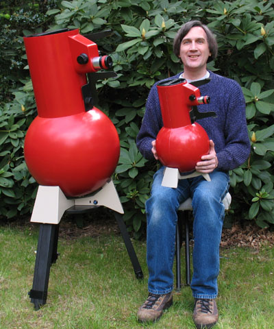
A Highest Etendue Telescope (HET) maximizes light throughput into the eye provides extraordinarily wide fields at maximum exit pupil. The view through such a telescope is noticeably different: very faint large objects in context with amazing detail. Think of a 100 degree eyepiece with a coma corrector and a very fast mirror. Unlike traditional Richest Field Telescopes that are smaller aperture with low power eyepiece affairs, an HET is meant to be used across a wide range of magnifications.
The first HETs designed for 100 degree eyepieces include Mike Lockwood's 14.5 inch [36cm] f2.55 and my 13.2 inch [34cm] f3.0.
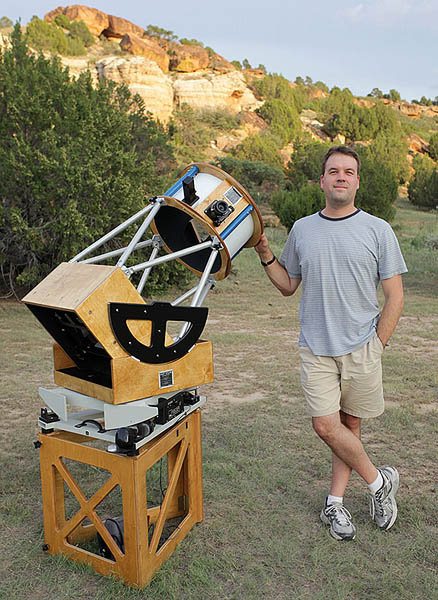
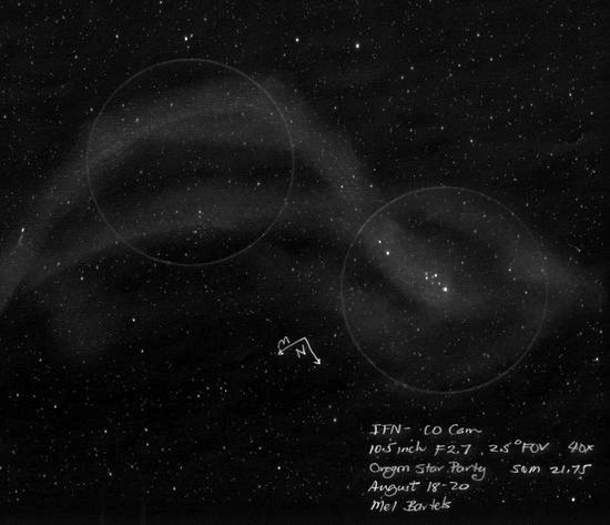
I could see with first light that the 13.2 inch that views are qualitatively different. I set about going down this path of thin fast meniscus mirrors, participating in the newly formed Altaz Initiative's efforts to create 1-2 meter telescopes at a fraction of the current cost. To solidify my fast mirror making skills, I made 6 inch f2.8 and 10.5 inch f2.7 telescopes. First light with these scopes revealed the Pleaides Bubble, the Andromeda Twist, and later, astonishing views of Integrated Flux Nebulae.
Sketching with my 6 inch: Betelgeuse's ring of dark nebulae:
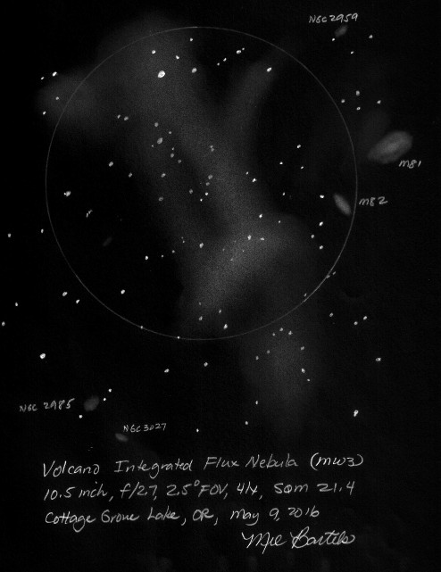
Sketching with my 10.5 inch: first drawing of an IFN:
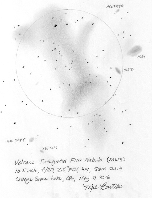
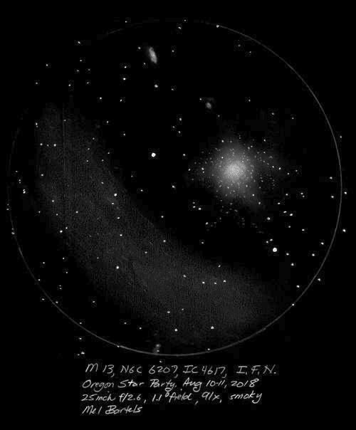
Sketching with my 25 inch [64cm] f2.6: Integrated Flux Nebulae in the field with M13 the Hercules globular cluster:
A simple rule of thumb for maximum etendue is aperture (inches) = 25 / object size (degrees)
The formula is focalRatio = eyepieceFLmm / eyePupilmm.
Your eye's pupil mm Eyepiece focal length mm Coma corrector magnification factor Resulting focal ratio is
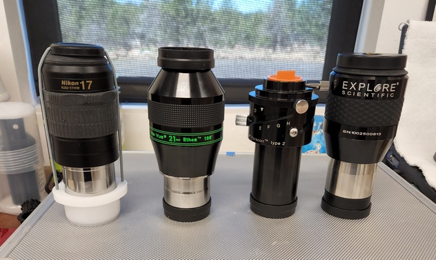
I have five low power wide angle views that give me good etendue. These low power wide angle views trade field for detail. For example, the 17mm Nikon shows significantly more detail than the 25mm ES with the Baader CC but at a cost of field. Here is the eyepiece data for my 30 inch [76cm] f2.7 scope.
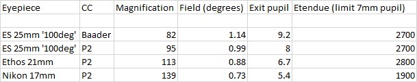
I find observationally that an oversized exit pupil maximizes the brightness of the field while maintaining the widest possible field. The eye is filled with as much light as it can handle: there is no light throughput wasted though some aperture may not be used. And it is easier to center the eye within the oversized exit pupil.
The scope that is best for you is the one maximizes the advantages that you see and minimizes the disadvantages that you wish to avoid. Here are topics to consider.
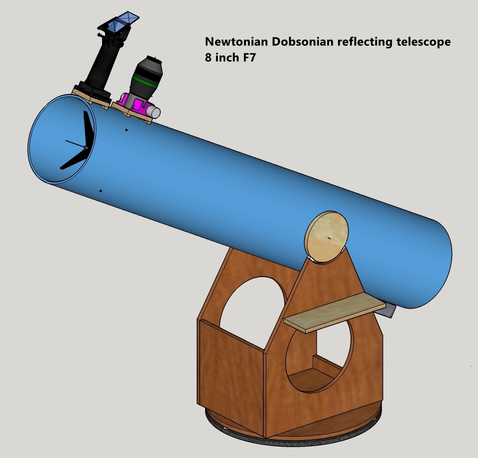
An 8 inch [20cm] f6-f7 is an great choice when equipped with appropriate eyepieces. It is the perfect balance between aperture and portability, between short and long focal lengths; it is easy to align and point. Inexpensive eyepieces work nicely with a wide range of magnification. And if you wish to make your own primary mirror, it is a straightforward mirror that you can grind, polish and parabolize.
Here are two of the many 8 inch [20cm] telescopes that I have built.
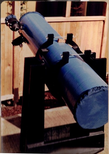
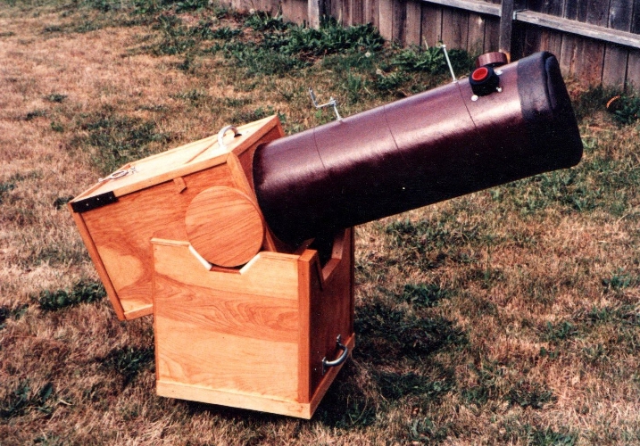
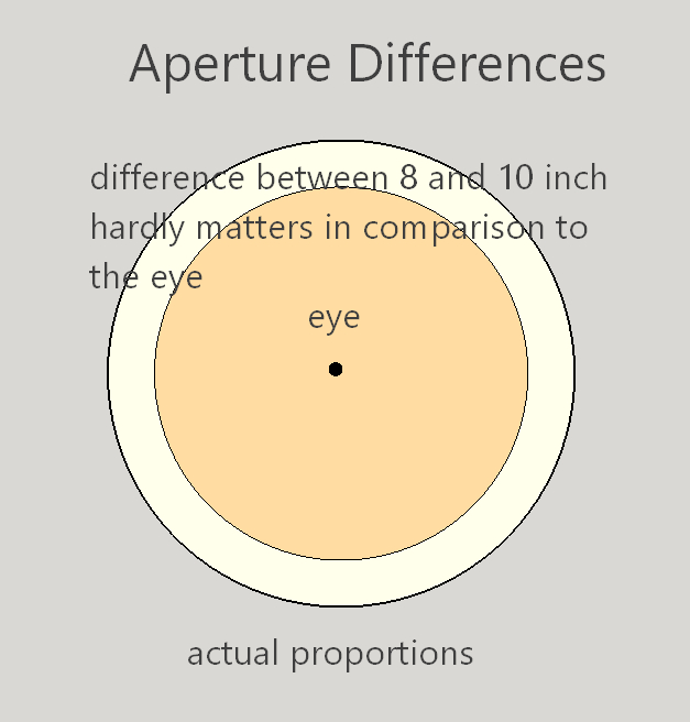
What matters most is an aperture that is significantly larger than the unaided-eye. The next equivalent jump up is to a 200 inch telescope!
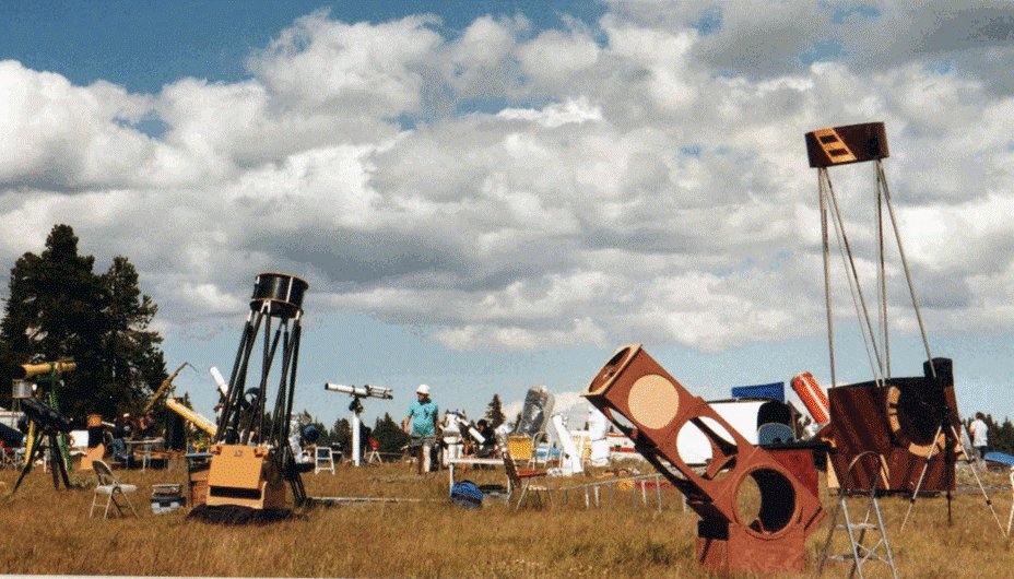
From 25 years of Oregon Star Party Telescope Walkabouts, 16 inch [41cm] size is the most popular large scope size.
Amateurs sometimes combine a small scope with a large scope, maximizing etendue for more than one true field of view.
I have made a number of combination scopes: 30/6 inch, 20/6 inch, 17.5/6 inch, 24/6 inch and 14/4 inch sizes. Particularly effective is mounting the secondary scope so that the eyepieces are close together.
Optically, which includes the primary mirror's figure and thermal properties along with the diagonal and collimation, should reach at least 12x per inch of aperture [0.5x per mm of aperture] before the image falls apart. Double this if you are into high magnification observing and your seeing conditions warrant.
Maximum field of fiew in degrees as seen in your widest field (typically lowest power) should reach 25 / aperture in inches [750 / aperture in mm]. It's quite ok to go wider than this as you gain a wider field of though at the expense of not using the entire aperture. In Newtonians, the diagonal shadow becomes an issue with pupils > 9-10mm.
No single carryable part of the scope should exceed 30 pounds [call it 15kg]. You can exceed this if you are younger and stronger. For example 'truss' telescopes are often broken into the mirror box, the trusses and the upper end. The mirror box is typially the heaviest and should not exceed this weight. This goes for the rocker and ground board too. When breaking the telescope down into ever smaller sections, keep in mind the assembly or setup time. For large scopes that are moved in a wheel barrel fashion, the lifting weight on the handles should not exceed this weight. For travel scopes the weight necessarily includes all the components. Travel scopes save weight by using the rocker as the travel case.
One metric is 'pounds per area of aperture', or in English units, pounds per square inch (PSI). Ultra-lightweight scopes achieve a PSI of under 1.5. For a lengthy discussion see the Cloudy Nights topic.
Setup time should not exceed 10 minutes. This includes time to tune up collimation.
The time for the mirror to settle down and reach proper parabolization should not exceed the setup time.
Telescope structures should dampen quickly (fraction of a second) and have a high harmonic frequency or resonance (10 Hertz).
Adequate alignment should be maintained in all telescope orientations. The accuracy required can be found on my main telescope design page.
A push or pull friction of about 2 pounds [1kg] is ideal. Much more than this and the telescope becomes a hefty and even dangerous 'herk and jerk' situation.
Looking through the focuser or eyepiece with the widest field size, only glass and blackness should be seen. Not the sky, not the ground.
Best to be able to sit at all telescope orientations, or otherwise stand. More than a step or two up a stepstool becomes an exercise in safety and leg soreness.
The telescope should fit into the car that you will transport it in; fit through the door of your home or garage.
Yes, you can make your own telescope including grinding your own mirror if you desire. You can make as much or as little of the telescope as you wish.
Grit, perseverance and creativity are more useful than raw intellectual power. Telescopes are built with the hands as well as the mind.
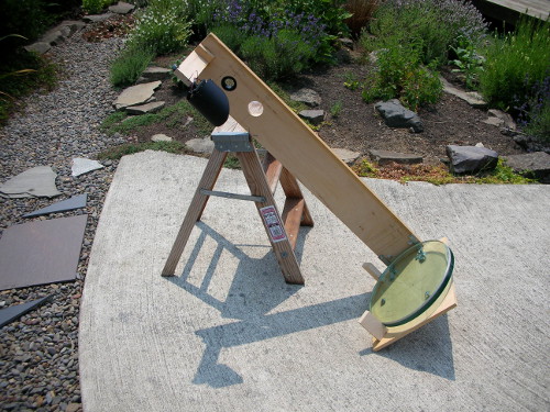
I suggest starting with a focal length of 48 inches and a mirror of 8 inch or 10 inches on a sidewalk mount.

Here's how I design a telescope.
Smaller apertures resolve less, produce images that are less bright, are more easily collimated, easier to focus, less affected by seeing and are lighter and less expensive.
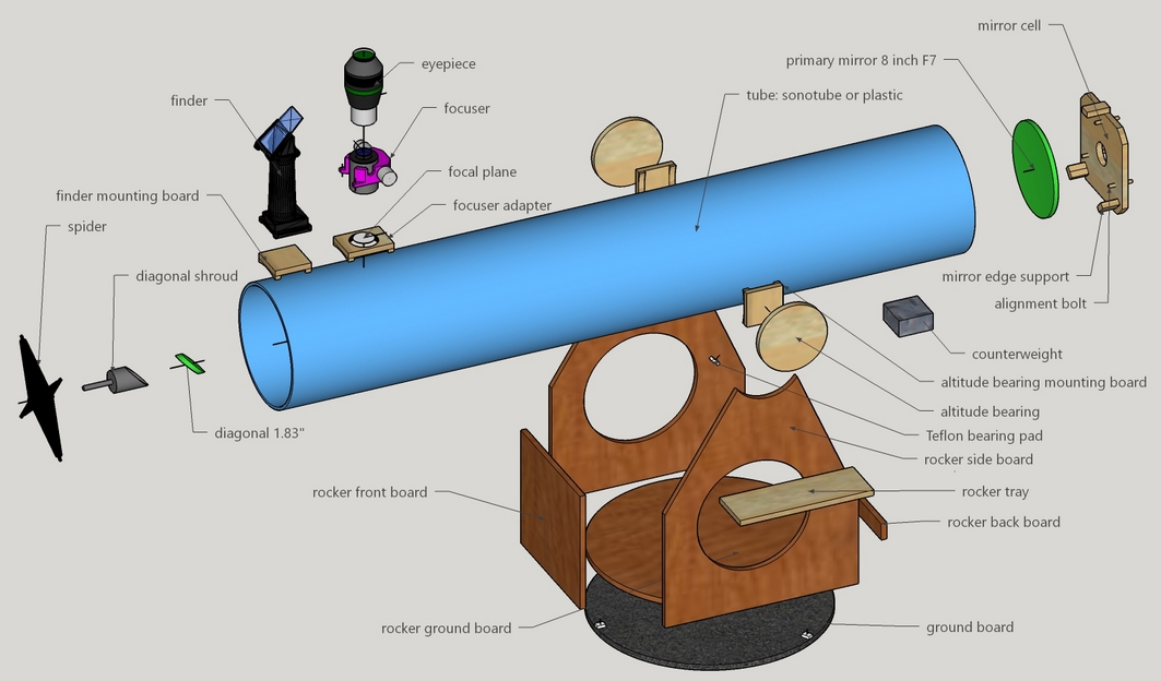
A sidewalk telescope uses a mount design popularized by John Dobson and the San Francisco Sidewalk Astronomers. The tube assembly 'rocks' up and down in a easy to make, non-precision design. Key is the PTFE (Teflon, UHMW, Nylon) on a strip of Formica or similar.
Here are the parts you'll need to make.
See my rocker designer.
John Dobson's video is a great place to start.
Here's a comprehensive webpage detailing the design and construction of a large truss tube telescope.
Toshima Taki's making an 8-inch Newtonian reflector.
On a clear summer night, look up at the Milky Way. Gigantic clouds of innumerable stars form a stairway to heaven. But only with a telescope do these clouds reveal their true nature as first seen by Galileo: countless stars forming the spiral arms of our galaxy. What aperture will show the greatest number of stars in an eyepiece? Larger apertures reach fainter magnitudes but have narrower fields of view. The answer hinges on counts of stars at particular magnitudes, or what is called star density.
Here are star counts based on the same ratio of aperture to magnification as the unaided-eye: (figures adapted from Glenn, Sky and Telescope, 1980, adjusted for increased field of view of the latest eyepieces.)
| Aperture | Field (60 deg eyepiece) | Stars | Field (100 deg eyepiece) | Stars |
| eye (7mm) | 60 deg | 1300 | 100 deg | 3600 |
| 50mm | 8 deg | 2500 | 14 deg | 6900 |
| 4 inch | 4 deg | 2700 | 6 deg | 7600 |
| 8 inch | 2 deg | 2800 | 3.4 deg | 7800 |
| 16 inch | 1.1 deg | 2700 | 1.8 deg | 7600 |
| 32 inch | 0.5 deg | 2200 | 0.9 deg | 6200 |
As you can see, a broad range of telescope sizes show close to the maximum number of stars. Therefore we say that a telescope used with a widest angle eyepiece that yields an exit pupil of 5-7mm can be called a Richest Field Telescope - the richest field of stars possible in any single view.
Most any telescope of F7 or faster with a two inch focuser and low power wide angle eyepiece can operate as a Richest Field Telescope.
A Richest Field Telescope optimally balances aperture, field of view, magnification and star density to grab the greatest number of stars visible at any one time in the eyepiece.
The idea was originally proposed by Mr. Walken in Knowledge (now Discovery) in 1916. He writes in part, "My chief part was in perceiving and publicly pointing out how every aperture could be made 'an' RFT, of that aperture, for a given observer and that there was one of all these which, in connection with the curve of star density against magnitude of stars, was uniquely 'the' RFT for the observer, in respect of maximum countable number of star per apparent square degree." He concludes, using star counts published in Knowledge, 1914, that a 2.5 inch aperture has the greatest star count, though he goes on to say that the view through a 6 inch is "little inferior" and that the views through larger apertures "is decidedly more attractive and 'richer'." He calculated a star count of 423 given a 50 degree eyepiece. Incidentally, he concludes that a magnification that yields the maximum possible exit pupil is best: too low of magnification wastes light and too high of magnification narrows the field of view dropping the star count.
It's plausible that the table of star counts or density in 1914 set the stage to conceive of richest field telescopes. If so, then this is an example of information driven revolution. So perhaps we can set the origination date to 1915.
In 1936 an updated star count was used to revise the RFT aperture to 4 inches with the count of stars as high as 711. Further discussion about the values of star density resulted in the conclusion that the RFT aperture is closer to 7 inches. Finally there's a note that a brightened background due to the Moon (today, we sadly have to add light pollution) dramatically increases the optimum aperture perhaps to 10 to 12 inches.
Clyde Tombaugh, discoverer of Pluto, built a 5 inch RFT in 1935. Clyde describes the views as "truly marvelous", mentioning how "dark nebulae in Sagittarius stand[s] out beautifully, as it does on a moderate exposure photograph." While Clyde extols the virtues of observing in Sagittarius, he says that the most beautiful and richest star fields are in the Cygnus region.
In a 1980 Sky and Telescope article, Glenn Shaw takes up the question of the best RFT aperture, using the latest star density values. He concludes that an aperture of 9 inches is best though he employs a scope of 5 inches aperture. He adds an interesting graph where only stars brighter than 5th magnitude in the eyepiece are counted. This favors apertures closer to 24 inches. Since Glenn's numbers are the latest that I'm aware of, I use these, adjusted for wider angle eyepieces available today.
H.R. Suiter notes in 1996 that the best RFT aperture has varied from 1.5 inches to 12 inches depending on revised star density values. Because of this to and fro with aperture, Suiter concludes that a rich-field telescope is best defined as one that can be used with an eyepiece yielding the maximum exit pupil that your eye can open to. He recommends personal experimentation since the aberrations of the eye are so substantial that star counts may not increase beyond 5 to 5.5 mm exit pupil. He makes an interesting comment that earlier observers would be awe struck by today's short focal ratio refractors and high quality high angle eyepieces, but that modern observers would envy earlier observers' dark skies even more!
One of the most successful commercial telescopes of all time is the Edmund Scientific Astroscan, a 4 inch f4 wide field telescope. Norm Sperling, co-inventor, estimates that 90,000 units have been sold. Jerry Oltion built a double sized replica of 8 inches aperture that garners considerable interest whenever it is setup.
Mike Lockwood's 14.5 inch F2.55 (image credit Mike Lockwood). Read Mike's report on the telescope.
Faint stars don't impress me. Hmm, OK, then increase the aperture. The star count is about the same, but the stars will be brighter with larger aperture, the best aperture being broadly centered on 24 inches.
How about counting the total starlight, not just the star count? Then the best views will be with the greatest aperture. The counts of the dimmest Milky Way stars do eventually bottom out: an aperture of 24-60 inches works best.
How about colors in stars? The colors and hues of stars become striking with aperture. In my 30 inch at low power richest field views the colors are astonishing, whereas in my 6 inch the stars are a much dimmer gray-white in comparison.
While any aperture telescope with a low power wide angle eyepiece can operate as a Richest Field Telescopes, the smaller apertures are more popular. Reflectors are popular down to 4 inches [10cm] aperture, refractors tend to more more popular for smaller apertures and binoculars popular for the widest fields.
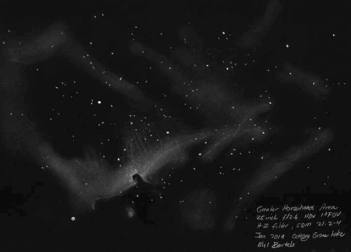
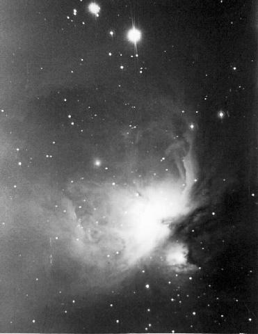
One reason that smaller apertures dominate is ergonomics. The Edmund sold 90,000 Astroscan telescopes in part for their ease of use and portability. Plop the scope down, point in the general direction and voila! If we compare fields of view, we can see another reason. Here are comparisons of 6, 10.5 and 13.2 inch apertures [15cm, 27cm and 34cm] set to their maximum possible fields (4.5, 2.5 and 1.8 degrees) given 100 degree eyepieces at a focal ratio of F3 of the North American Nebula, the Orion and Horsehead nebulae and the Lagoon and Trifid Nebulae.
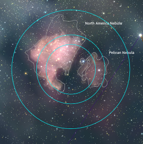
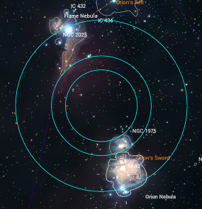
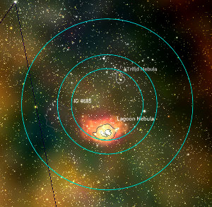
You can see that the 10 and 13 inch aperture fields are not that dissimilar where as the 6 inch aperture has a much larger field.
Here are the eyepiece focal lengths for different focal ratios and exit pupils. At the faster focal ratios, Newtonians need coma correctors. The TeleVue coma corrector multiples the focal ratio by 15%. Using this corrector alters the values.
| Exit pupil | f/3 | f/3+P2 | f/4 | f/4+P2 | f/5 | f/6 |
| 8mm | 24mm | 28mm | 32mm | 37mm | 40mm | 46mm |
| 7mm | 21mm | 24mm | 28mm | 32mm | 35mm | 42mm |
| 6mm | 18mm | 21mm | 24mm | 28mm | 30mm | 36mm |
| 5mm | 15mm | 17mm | 20mm | 23mm | 25mm | 30mm |
| 4mm | 12mm | 14mm | 16mm | 18mm | 20mm | 24mm |
| 3mm | 9mm | 10mm | 12mm | 14mm | 15mm | 18mm |
| 2mm | 6mm | 7mm | 8mm | 9mm | 10mm | 12mm |
| 1mm | 3mm | 3.5mm | 4mm | 5mm | 5mm | 6mm |
I have found over the many years from observing with a variety of telescopes as fast as F2.6 and a variety of apertures up to 30 inches [76cm] that a slightly oversized exit pupil gives the best combination of field and brightness.
You've convinced me about stars, how about nebulae? I understand that the greatest number of stars are seen with the largest exit pupil that my eye opens to. And that the star counts don't vary that much with common apertures. But I'm uncertain how best to view nebulae: lowest power, medium power, high power; more aperture, less aperture? We need to satisfy two conditions: 1) that the nebula be recognizable and 2) that it be detectable.
For the nebula to be recognizable it has to fit substantially within the field of view. Consider perhaps the grandest nebula of all, our Milky Way Galaxy. Imagine looking skyward on a summer night from atop a ladder in a field with distant horizons. Looking up at our galaxy overhead we imagine ourselves floating in space 30,000 light years from the monster black hole that dwells in its center. We imagine the unimaginable immense galaxy stretching out in front of us. Though we cannot sense it, we are spinning around the black hole at 150 miles per second. We can see the central hub peaking up and the giant spiral arms twisting in front of us. At a particular time in the spring, we can see the entire galaxy rim the horizon. It's impossible to make these wonderful observations using a high powered telescope pointed at a tiny fragment of our galaxy. So the nebula has to fit in the field of view to be distinguished.
How about showcase objects as examples?
The Pleiades
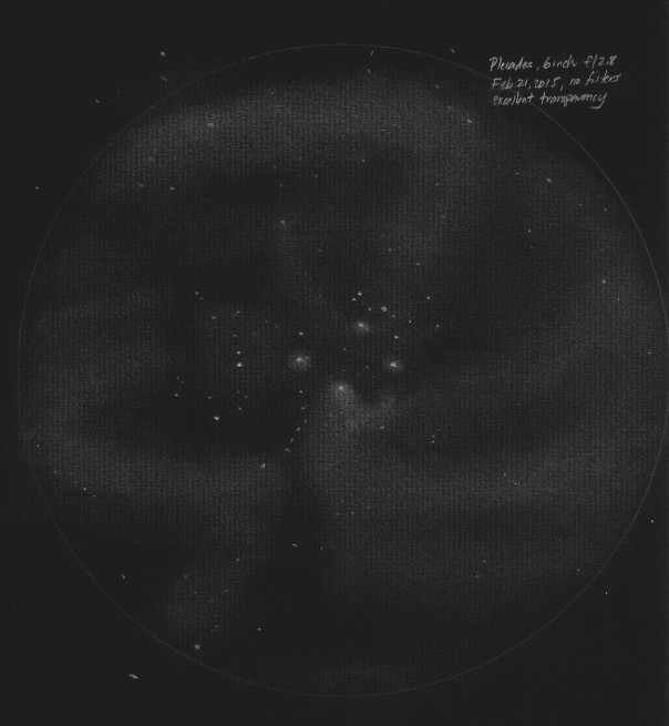
I was astonished to see an irregular bubble of faint nebulosity surrounding the Pleiades, visible by virtue of the 4+ degree field of view and the 6 inches of aperture. Later it took me some time to find a deep digital image that showed the bubble as faint extensions of the Milky Way. Wow!
The Horsehead Nebula
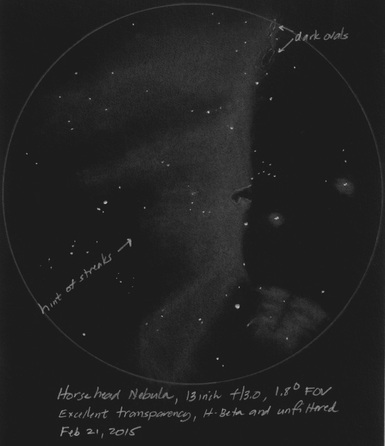
The Horsehead is about 8x6 arc-minutes in size but needs the nebulosity that it's embedded in to be framed, so let's say something closer to a half degree. An aperture close to 50 inches looks to be ideal. That we can see it in scopes as small as 5-6 inches and that we can see it nicely in 20+ inch scopes is a testament to our eyes. Before we pat ourselves too much on the back let's analyze the smallest aperture that we successfully detected the Horsehead. 5-6 inch aperture at 6mm exit pupil with a 70 degree eyepiece yields an apparent size close to 3 degrees, which matches our three degree apparent size rule from above!
The Milky Way is full of bright and dark nebulae of all sizes. Telescopes of all apertures will give exciting views if they are used at large exit pupils and widest angle eyepieces. If aperture is decreased then the field of view will contain many Messier and NGC objects: the point being to observe the panorama taking in the surrounding nebulosity and stars. If the aperture is increased then the field may contain one or two objects: the point being to observe detail.
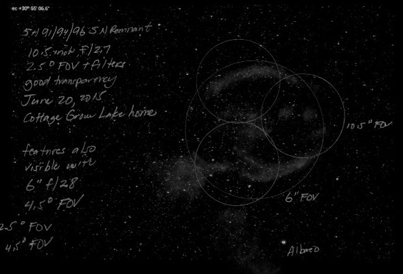
The faint supernova remnant G65.3 5.7 just north of Albireo
How about galaxies?
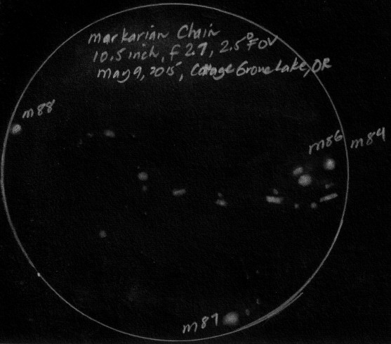
Groupings of galaxies are beautiful through a Richest Field Telescope. With my 10.5 inch [27cm] f2.7 with 2.5 degree field scope, field after field is littered with galaxies; 5-20 galaxies in any field of view as I sweep through the Virgo / Coma Berenices region. The shapes of the galaxies can vary dramatically. I call this 'Richest Galaxy Observing'. For example, field after field of galaxies at the edge of visibility in SW Gemini as illustrated by my sketch with my 30 inch f2.7 telescope at 100x with a one degree field of view.

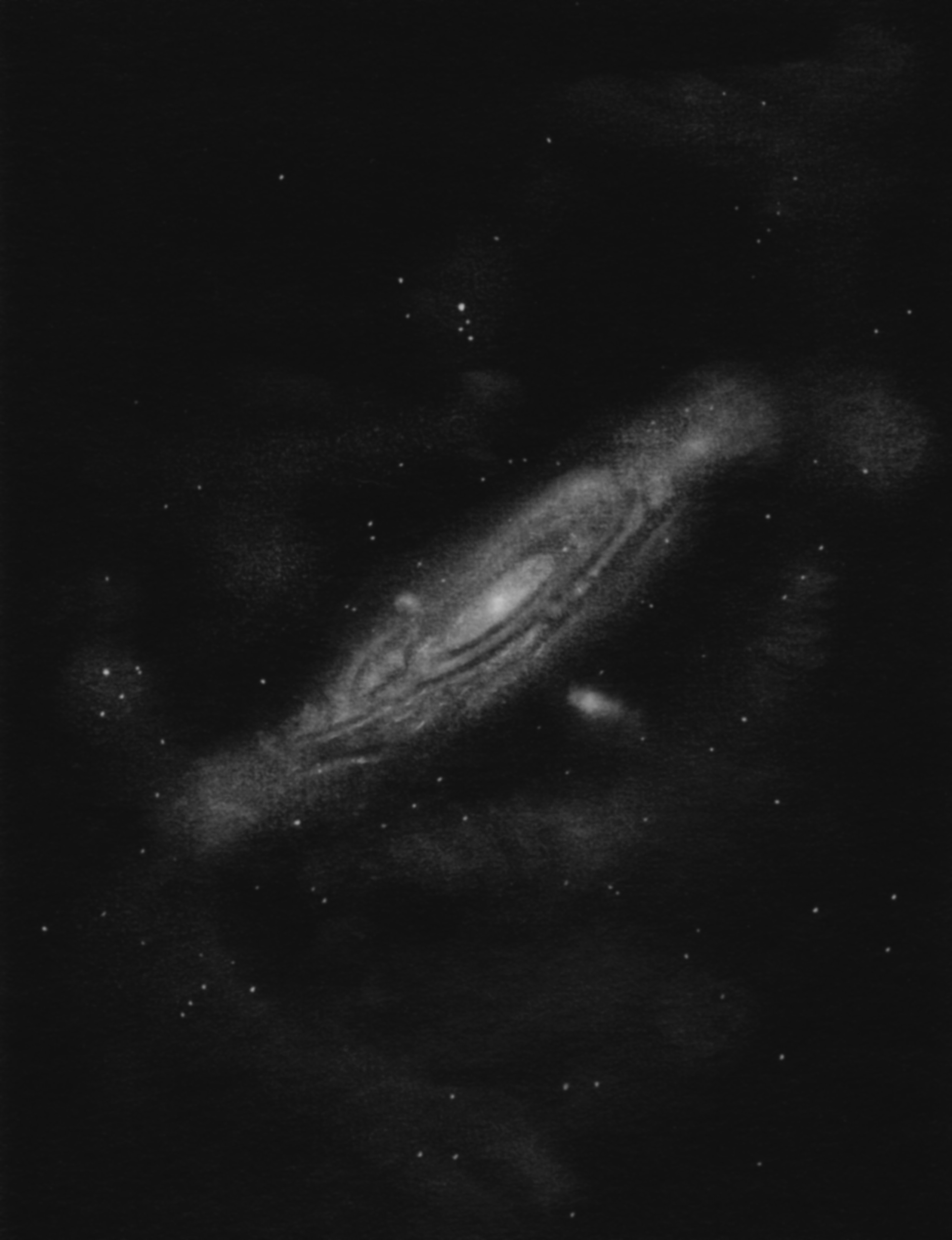
By moving the scope around we create a larger virtual field of view, showing us surprising objects such as galactic cirrus or Integrated Flux Nebulae near M31. The 30 inch F2.7 telescope's low power field is 1 degree, and by moving the scope I can create a virtual field that is several degrees wide.
Aren't RFTs meant for low power, have sloppy optics and produce poor high power views?
Wide angle scopes are extremely challenging to design and build. Optical quality must be high, the difficulty of grinding fast mirrors is very high, alignment and focusing are far more critical and illuminating and baffling wide angle views are difficult. After dealing with F3 RFTs, building a F7 scope is 'easy-peasy'.
Particularly with medium apertures, I want my telescope to perform at high powers too. Tiny nebulae require it and glittering globular clusters are stunning when they fill the high power eyepiece. There is no compelling reason for planetary viewing to suffer. My 6 inch f/4 resolves the Galilean moons at 300x. It is an outstanding mirror, the focuser is high-end and the optical alignment perfect. Factors such as collimation and focusing accuracy are much tighter with a f/4 compared to a f/6. Notwithstanding, the planetary views through my 13.2 inch and 10.5 inch at 300x and 250x respectively are beautiful: razor-sharp with no scatter. Jupiter's recent triple-moon conjunction was memorable.
What about those large diagonals that fast wide angle telescopes call for? First of all, slightly larger diagonal sizes do not significantly impact image quality, rumors to the contrary. Also, at f/4 and particularly at f/3, the illumination fall off, that is, how much does the light dim as you look towards the edge of the field, is very gradual. So, a diagonal size that fully illuminates only the center of the field will do nicely. My 13 inch f/3.0 RFT uses the same diagonal size as Coulter's original 13 inch f/4.5. An 18 inch scope calls for a diagonal to eyepiece distance of 12 inches, and if the mirror happens to be a f/4, then a 3 inch diagonal will work fine. This is a diagonal to primary ratio of 6:1. At this ratio, image degradation due to the diagonal obstruction is practically insignificant.
Observing with the new RFTs have opened the door to sketches of very difficult faint objects: most surprising of all, Integrated Flux Nebulae.
Here's my catalog of IFNs and the fascinating story of visual observations extending all the way back to William Herschel.
And check out my drawings....
Sky and Telescope magazine, March 1980, by Glenn Shaw, pages 192-4
Amateur Telescope Making Book Two, by Ingalls, pages 623-630.
ATM III, pages 389-417, by Ingalls, publisher Willman-Bell
Collimation, or optical alignment, is the act of bringing the eyepiece and focuser axis coincident with the primary mirror's axis.
Many amateurs have trouble with collimating their scopes. At a recent dark sky star party five of the seven Dobsonian telescopes were horribly mis-collimated. Many amateurs are not aware that they should check collimation, they do not know what to look for, and run into troubles attempting to collimate. Further, there is a misconception that collimation is a bit of a black art and that fast mirrors are impossibly difficult.
Collimation consists of:
It is certainly possible to collimate the telescope yet have a poorly positioned diagonal that does not evenly illuminate the field of view. Adjusting the diagonal to its offset position for even field illumination is commonly incorporated into collimating the telescope, making collimation more difficult and confusing.
The focuser's axis should be aligned perpendicular to the primary mirror's focal plane so that the stars focus accurately across the field of view. Alignment accuracy is based on factors such as focus depth, de-focus not to exceed quarter wavefront deformation, and the eye's ability to accommodate across the field, among other factors. Needed accuracy (projection of the focuser axis onto the primary mirror's center via a laser) can range from 1/8 inch [3mm] at F3 to an inch [25mm] at F8.
The primary mirror's axis should be aimed back onto the focuser's axis accurate to the coma-free diameter (where coma is less than a quarter wavefront) of the mirror. Needed accuracy can range from 1/50 inch [0.5mm] at F3 to an 1/3 inch [8mm] at F8. Invariably, the primary mirror's axis alignment is the more critical of the two.
Experimenting at the eyepiece of my fast sub-F3 scopes, testing for sharpness of focus and visibility of detail, I find that the primary mirror axis alignment is the more critical of the two alignments. This is consistent with theoretical considerations.
It appears to be a little known reality that, once aligned, rarely does the primary mirror need realignment. This is because the diagonal holder invariable works lose. The key is to start by adjusting only the diagonal holder such that the eyepiece and focuser axis is once again coincident with the primary mirror's axis.
One of the biggest issues is trying to center the diagonal under the focuser while collimating. I can attest that this is confusing and frustrating. Far better to align the focuser first, then position the diagonal properly, ensuring that the diagonal is properly centered under the focuser. I use a target on the far side of the upper end to line up the focuser like this.
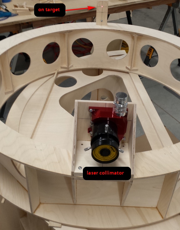
I then add the diagonal, keeping in mind the diagonal offset to center the field illumination. Collimation at this point is a breeze: adjust the diagonal rotation and z-axis slightly by centering the primary mirror reflection in the diagonal, tilt-tip the diagonal to center the laser collimator dot on the center dot of the primary, finally adjusting the primary so that the laser collimator's reflection is centered on itself.
Better is a 'collimate once while building' philosophy. That is, build the collimation into the telescope, then never adjust it again. That's best done by building without any adjustments that can loosen.
Also, center dotting or donuting the primary is not necessary. I align the diagonal to the focuser, then use a laser collimator to align the focuser axis to a central mark on the mirror cell. I place the mirror in the cell, measuring beforehand that the mirror is precisely centered, guaranteeing that the laser collimator hits the mirror center without need for a collimating ring stuck to the mirror's center. I then adjust the primary mirror cell collimation bolts to align the laser beam back onto itself at the focuser. So, no central marking or placing a donut on the mirror's face. This works perfectly: the diagonal shadow breakout was exactly centered in the light of the star disk.
How many of you check your collimation with the telescope aimed vertically then with the telescope aimed horizontally? That's dynamic collimation, demanded by fast F5 and even faster F3 telescopes.
Notice a difference? That's bad news. The best one can do is to stiffen the telescope and aim it partway up the sky so that any drift in collimation is split between vertical and horizontal orientations. But what angle should be used? Andrew Bell has derived a formula for collimation error as a function of collimation angle that takes into account better seeing when the scope is aimed higher and proportion of sky that's observable from horizon to zenith. Mathematically, he used his formula to find a 'best' collimation angle that will minimize RMS collimation error as your telescope is pointed across the whole sky.
Andrew found that the optimal angle to collimate at is 48 degrees up from the horizon. He's also calculated that this is a broad answer in that a few degrees higher or lower gives very close to the same results.
In dynamic collimation, the scope is aimed at this angle (use an angle finder available from hardware stores) and collimated. Then check the collimation when the scope is aimed vertically and again when aimed horizontally. Verify that any dreaded collimation change is split between the two orientations. That's the best that can be done for the moment. If noticeable movement is found then stiffen the telescope structure including the diagonal holder and spider.
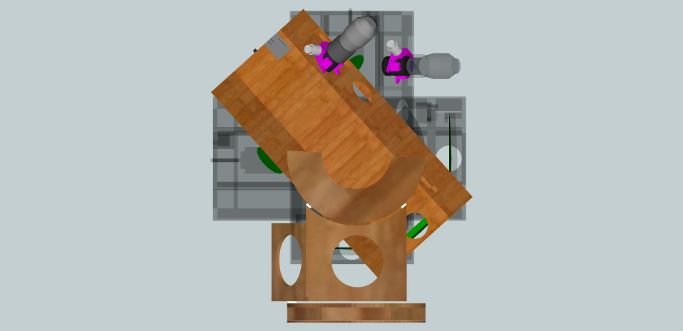
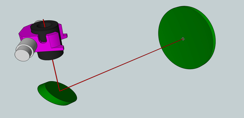
It's important to understand the single requirement of collimation, namely, that the eyepiece axis and primary mirror axis be coincident, or on top of each other. Here we see the situation prior to collimating where both the diagonal and the primary mirror are out of adjustment.
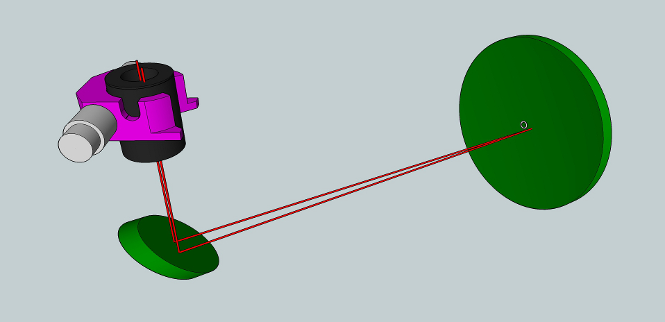
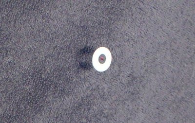
First the diagonal is brought into adjustment by making the laser beam point to the exact center of the primary. Closeup of laser centered in notebook ring that's carefully placed at the mirror's exact center.
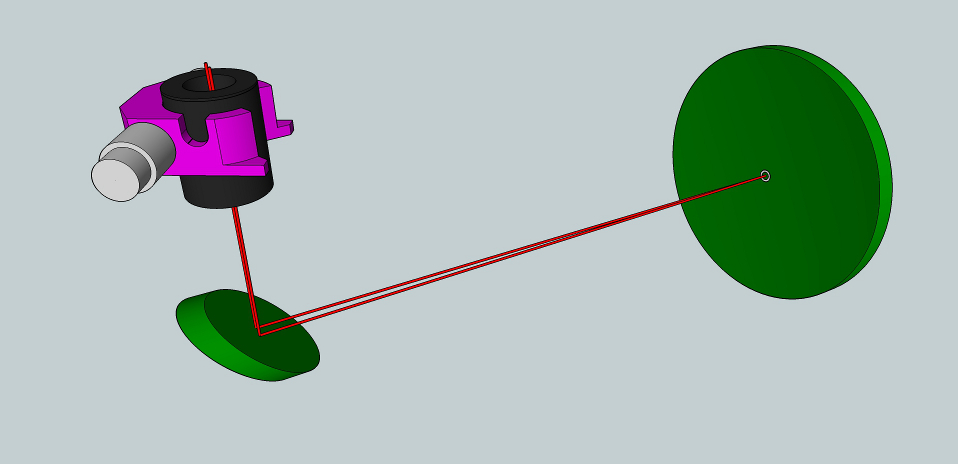
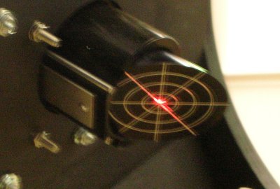
Finally we adjust the primary mirror's collimation screws so as to aim the laser beam's return upon itself. Closeup of centered laser return.
For those using setting circles or computer control, the optical axis needs to be coincident or collimated with the mechanical axis, otherwise pointing and tracking errors occur.
A. E. Conrady gives the formula for the limits of de-focus where the optical path differences do not exceed the Rayleigh limit. In other words, the optical path difference between inside of perfect focus and outside of perfect focus does not exceed 1/4th wave.
Focusing tolerance = wavelength of light / sin^2(angle of light from the mirror's edge to the focal point).
The sin of the light's angle is mriror radius / focal length; 2 sin (angle) is twice this, which is the reciprocal of the focal ratio.
Therefore the formula simplies down to 0.000088 * the square of the focal ratio.
Here is a table of focusing tolerances per focal ratio:
| Focal ratio | Focus tolerance |
|---|---|
| f3 | 0.0008 inches [0.02mm] |
| f4 | 0.0014 inches [0.04mm] |
| f5 | 0.0022 inches [0.06mm] |
| f6 | 0.0032 inches [0.08mm] |
| f8 | 0.0056 inches [0.14mm] |
| f10 | 0.0088 inches [0.22mm] |
Fast scopes demand precision focusers with ultra-fine adjustment and no tilt.
The theory of atmospheric seeing was developed in the '60's-'80's and is now well proven. Measuring the temperature structure coefficient predicts image quality (essentially, a plot of index of refraction versus altitude).
Seeing is directly related to high-frequency temperature fluctuations associated with turbulence.
Atmosphere above a site is divided into four layers: surface, planetary boundary, atmospheric boundary and the free atmosphere.
Turbulence is generated in the surface layer by wind shear due to frictional/topographic effects from the surface. Height of this layer set by the roughness of the ground, e.g., trees and boulders. Layer's extent is 10 to 100 feet high. Telescopes at Apache Point are situated up in the air so that the optics sit above this layer. Isolated peaks (not ridges) are best because air flows around rather than over the surface.
The planetary layer holds the air that's heated by the Sun and moves up and down vertically. The upper limit is the inversion layer, typically 3000 feet.
The atmospheric boundary layer sits on top of the planetary layer and is free of convention but is affected somewhat by the ground, e.g., mountains.
The free atmosphere is unaffected by the ground. Turbulence is caused by the jet stream, creating vertical temperature gradients above and below the jet stream, 7 miles up. Jet stream velocity is highest in the
mid-latitudes, so best to observe on nights when the jet stream is 'elsewhere'.
Inland sites can be quite good as long as they face into undisturbed air. Large flat plains downwind from mountain ranges can be as good as coastal or island sites.
Direction of light affected by differences in index of refraction of air.
Index of refraction of air changes with air temperature (not humidity, and not wind speed) in the free atmospheric layer or in the surface layer next to the scope.
Seeing depends on temperature differences and not on wind. The temperature difference between the adiabatic cooling rate and the actual air temperature is dissipated by the creation of smaller and smaller eddies on a fractal scale that eventually transforms into heat. Turbulence occurs in very thin 10-20 feet deep layers.
What is the structure of thermal turbulence?
Turbulent energy in atmosphere produced by buoyancy and wind shear on scale of tens of meters.
Energy created by turbulent eddies, and passes through the Inertial Subrange, where smaller and smaller eddies are created.
Eventually eddies on scale of millimeters created. Sheers in these small eddies are so large that air viscosity transforms their kinetic energy into heat, stopping the eddy creation process.
It's in the thermal subrange where thermal fluctuations occur.
R0, called the "Fried Length" or "coherence length", permits simple characterization of seeing.
R0 is the diameter of light rays that stay parallel through the atmosphere.
R0 at best sites range from 10-30cm [4-12 inches]. Seeing disk is 1/2 to 1/3 arc-second. The coherence time is 10-50 milliseconds and the isoplanatic angle is 2-10 arc-seconds.
Image degradation comes in two forms: image motion and image blur. Smaller apertures suffer from image motion and large apertures suffer from image blur.
Can be observed by noting the largest aperture where stars appear to shimmer yet are sharply defined. Larger apertures show steady but bloated stars.
R0, the Fried Length, suggests that the best aperture is 10-30cm [4-12 inches]. However, seeing is highly variable. For us in Oregon, in northwestern USA, when the jetstream is overhead seeing is atrocious, confirming the notes above. When the jet stream is elsewhere (British Columbia or California) seeing can be quite good. Further, locally, at my house, when the nighttime mountain breezes start, seeing disintegrates. Nonetheless, the breeze is not continuous and patience is rewarded with good views. There are nights of near perfect seeing, where magnifications from 750x upward can be used. Finally, there are the rare nights of perfect seeing. On one such night I double barlowed with a very high power eyepiece and reached 6000x on my 20 inch [51cm] F5. The stars showed perfect Airy disks. What was interesting, besides the weird effect of such a small exit pupil, was that fainter stars still looked relatively pinpoint-ish. The rings around the Airy disk were too faint to be seen and indeed, the Airy disk itself was not of equal brightness throughout and instead tapered towards the edge. Of course, resolution was not changed.
This matches my experiences observing through 40 inch [1m] telescopes on nights of good seeing at 750-1200x. The stars were pinpoints, aesthetically very appealing. Also visual observers favorably comment on viewing through 80 and 90 inch [2m and 2.3m] Cassegrains.
Therefore there is a subjective factor of up to 8X in visual observing depending on seeing conditions and observer patience.
The percentage of nights with excellent seeing versus average seeing is a probability function with a long tail. Nights of excellent seeing are one in ten to one in fifty, or several times a year.
Scopes larger than the Fried Length are also preferred when digitally imaging the planets. Perhaps the median scope here is a 16 inch [40cm]. MacEvoy says that the best aperture is 3.5 * R0, or ~ 14 inches [35cm] for R0 of 10cm. At this aperture it is virtually certain that lucky imaging will greatly increase image quality. That is because the extra aperture allows short exposures that freeze the seeing, the hundreds to thousands of images taken are gone through after the fact where the worst ones discarded and the best ones are stacked into a single image of exquisite detail.
Focus outward a bit or use a Ronchi eyepiece. Do you see variations fly past in one direction? That's high altitude seeing. At focus the image will appear fuzzy in a rather consistent way. Does the weather forecast calls for the jetstream to be overhead? The jetstream causes high altitude seeing.
Does the out of focus or Ronchi image look like a rapid jumble, rumbling around? That's medium distance heat sources, like house roofs and hot pavement. It can be caused by roughed up air, broken up by nearby mountains or forests.
Do you slow moving disturbances? That's heat problems right at the telescope: hot optics or possibly set up on hot asphalt. This is the type of seeing that makes stars twinkle.
If it moves, then it is bad seeing. The more it moves, the closer the issue is to the telescope.
Temperature issues cause distortions in most types of glass (exception being quartz or zero-expansion glass). The thicker the glass the greater the change and the longer it will take for the glass to reach equilibrium with the outside temperature. Of course the outside temperature falls during the night. Some optics may never reach equilibrium. Hence the adoption of air flow cooling approaches. If you see variation from night to night or during the night then that's seeing, not poor optics. Temperature effects are minimal in the morning hours.
Bely: The Design and Construction of Large Optical Telescopes, 2003, section 1.3.4 pg 13-, section 12.2.1 pg 394- (contains citations)
For a thorough and excellent treatment on the subject, see Astronomical Seeing, Bruce MacEvoy, 2012, part 1 https://www.handprint.com/ASTRO/seeing1.html, part 2 https://www.handprint.com/ASTRO/seeing2.html, part 3 https://www.handprint.com/ASTRO/seeing3.html
Field curvature in a Newtonian is minor compared to other optical designs. For example, consider optical designs of the same focal length. A Schmidt-Cassegrain will have a relative field curvature of 4x, a refractor 3x, while a Newtonian a relative factor of 1x, far flatter than the other two designs.
The coma of a fast Newtonian is quite bad. Luckily one can purchase a lens set called a coma corrector that removes coma.
A beautiful telescope opens the Cosmos, opens our soul, makes us feel alive. Our search for this beauty, for this quality, is the essence of designing, building and using telescopes. Patterns of beauty are all around us: in the Cosmos, in us. The stark vastness of the sky surrounds us; objects both bright and dim are simply wonderful. The telescope in our hands feels alive; we have a sense of the telescope: it feels good.
A telescope should look beautiful, not necessarily in the stain of the wood or the polish of the metal, but in a general sense. For example, the Palomar 200 inch Hale telescope is beautiful. The design unfolds through design patterns and morphological analysis. The scope is built, maybe parts re-built to remove annoying issues, then used under the stars. The value of a telescope is in the observations, the sketches or the digital images we make. I observe by sketching. As I do so, new ideas occur to me that might increase the telescope's value. I start designing the next scope, looking for beauty while I unfold the design (nothing to do with trial and error) through design patterns and morphological variation. Over time, step by step, this has led me into exciting new designs from which I make new observations of the universe above and all around us.
Mimicking nature, design should be alive by growing organically through incremental development, filling in details later as needed. The design must be simple and the implementation simple.
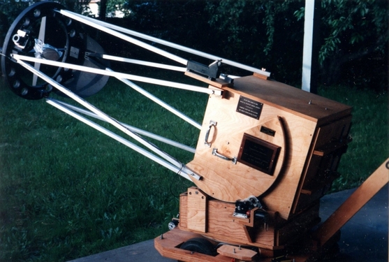
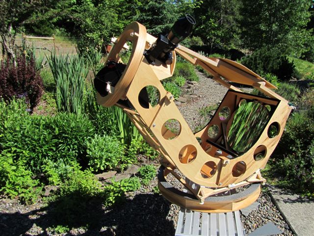
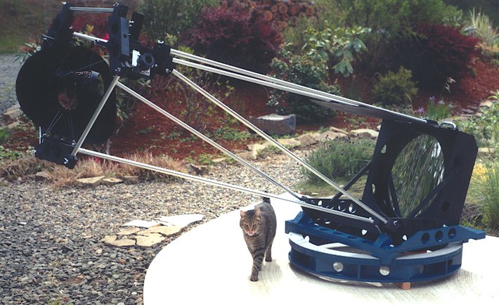
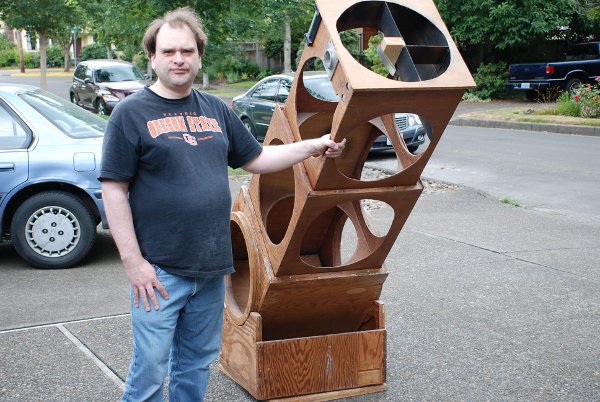
As an example, consider my 20 inch as it evolved through four iterations from 1994 to 2003. The initial design experimented with a single upper ring and computer control. Subsequent designs lightened the design. Ultimately I invented the TriDob for maximum portability through narrow RV doors, eschewing the computerized drive system.
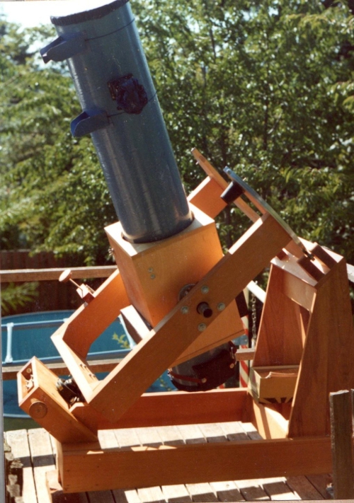
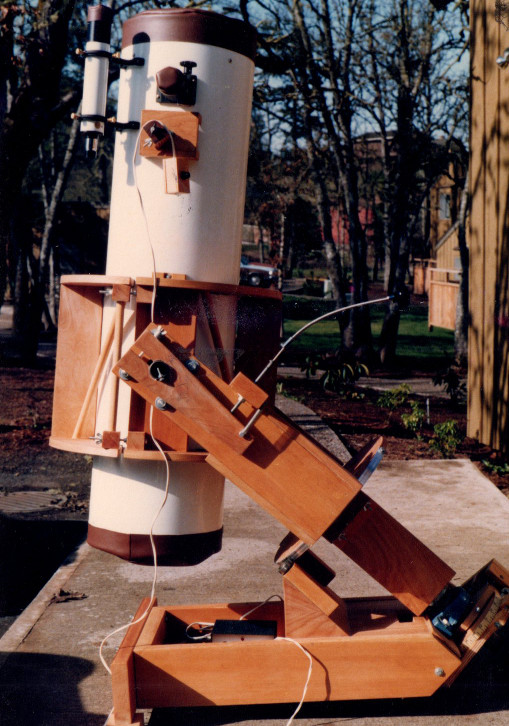
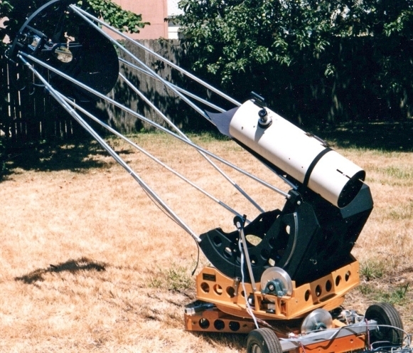
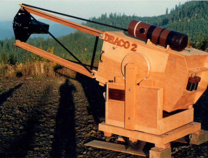
Two of my A-frame designs showing the evolution of my thinking: a 12 inch and a 24 inch that was trailered (1980).
A definition of elegant design is the optimal telescope that is achieved with the simplest, minimalist, least expensive effort. Elegance is the simplicity found on the far side of the complexity rainbow.
A pattern is a quality reusable solution to a common problem. Examples include stairs and gardens. Advantages of patterns: begin work at conceptual level, worry about details at the last responsible moment, incorporating knowledge gained during earlier iterations. Use language that users understand and judge what is of higher quality and more beautiful.
Telescope patterns include trusses, rockers, focusers, mirror cells and observatories.
Nature unfolds by breaking symmetry yet preserving structure. Breaking symmetry is a structure preserving change that strengthens centers and sharpens boundaries. Beautiful scopes have common characteristics: strong centers, clear boundaries, local symmetries and voids. Creativity is redefining us and our reality; it takes courage and endurance. Ideas can change; more than this they must change. We must master order so as to be open to chaos. To gain insight, we must love truth more than we hate error. Set high goals, identify critical functions, eliminate or improve functions then refactor and repeat. Example is the telescope tube: optics on both ends held with cylinder; cut away portions of the cylinder keeping only those portions that transmit load, leaving a truss or bay pattern. A large single cylinder can be replaced with numbers of smaller cylinders.
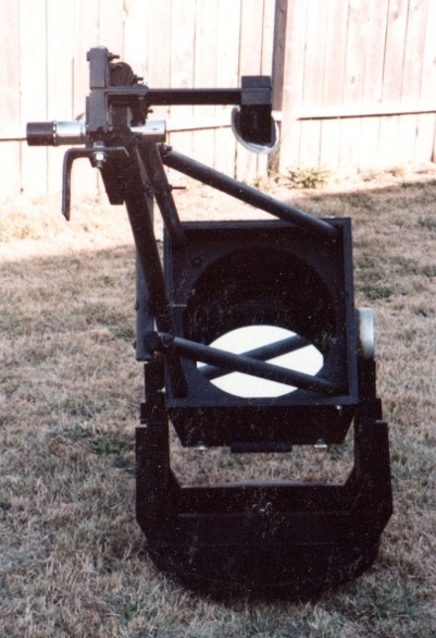
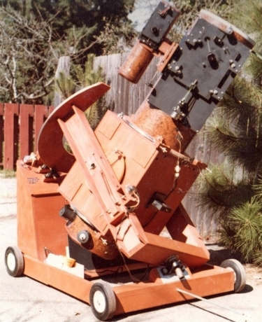
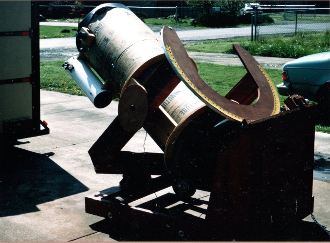
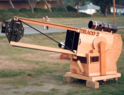
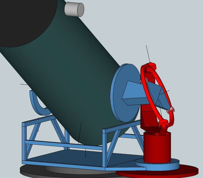
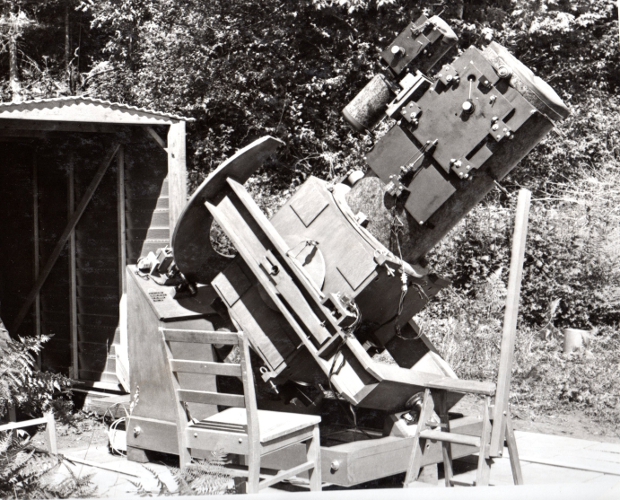
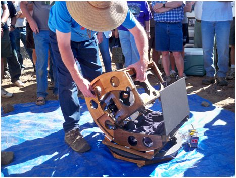
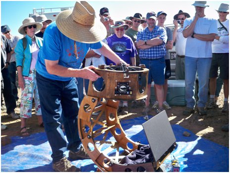
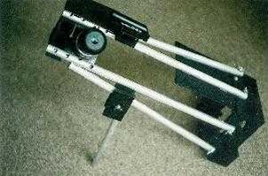
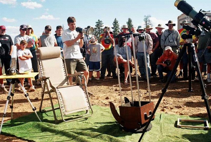
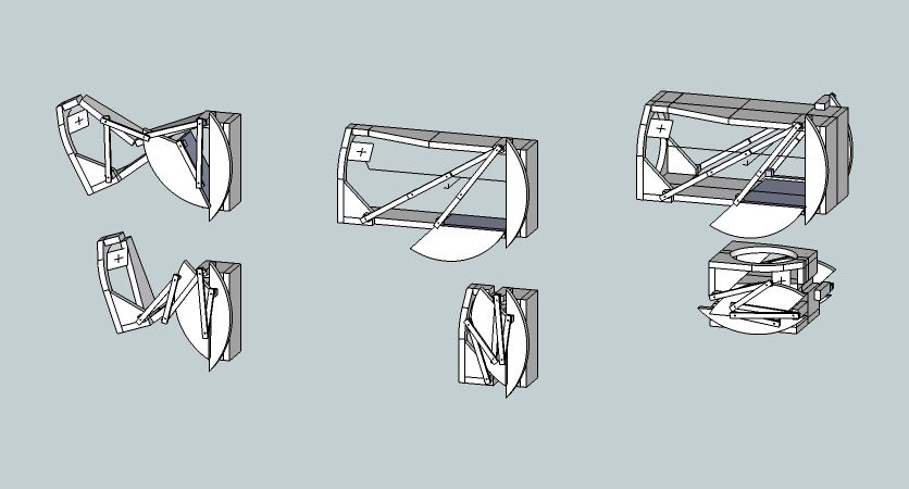
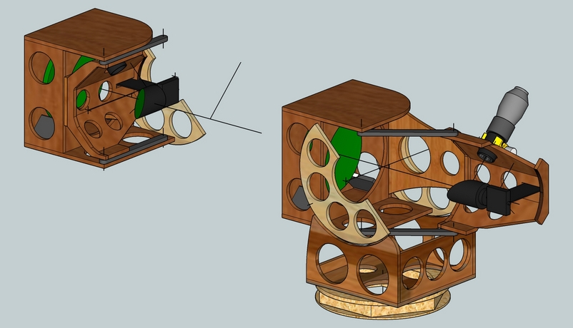
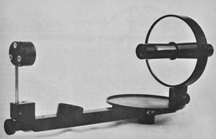
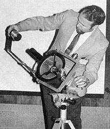
Example: Morse mounting from the 1940’s that used a mechanical drive system for an altazimuth mounting. This is the mechanical analogy to today’s software that translates between equatorial and altazimuth coordinates. The Morse mount is an equatorial to altazimuth mechanical computer. Look at the car in the background to set the age of this mechanical computer. Next is my evolution of the design, moving the analog mechanical computer to the side and incorporating an amillary design. See my webpage for more on the Morse Transformer mount and proposed modern derivatives
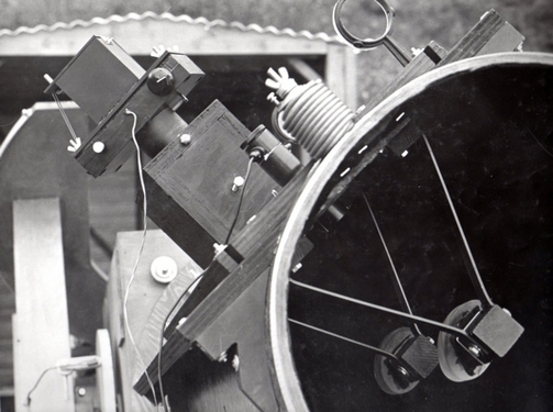
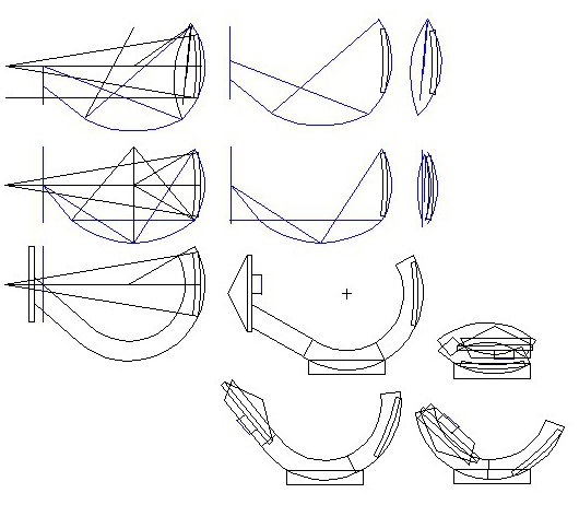
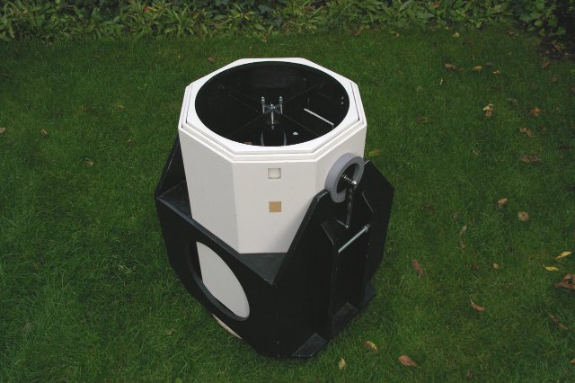
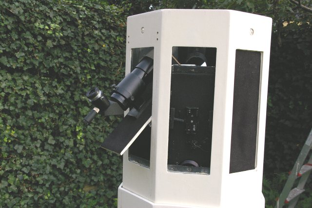
Example: the focal plane pattern. By providing a flexible interface, I could swap between visual and cold camera imaging. The imaging platform featured a centered guiding double diagonal arrangement where the second diagonal caught the light that squeezed past the initial diagonal. I did five minute nearly unguided images with a touchup of Declination adjustment due to slight polar misalignment with my 14 inch telescope. Image taken with my cold camera, five minute exposure, Tri-X film, using the 14 inch with the unusual guiding arrangement.
The Holcomb Mount, popular in the 1800’s, and my star testing stand.


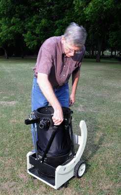
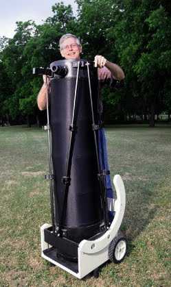
Evolution of my Glide Dob design

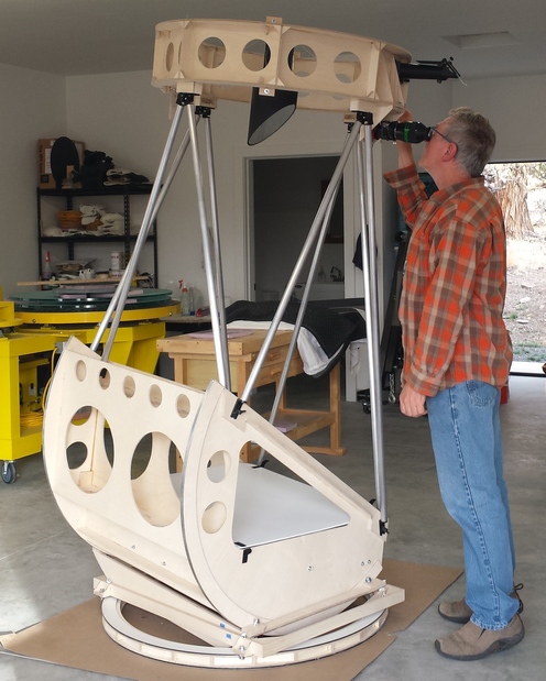
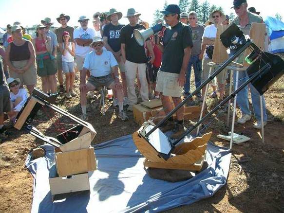
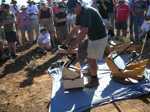
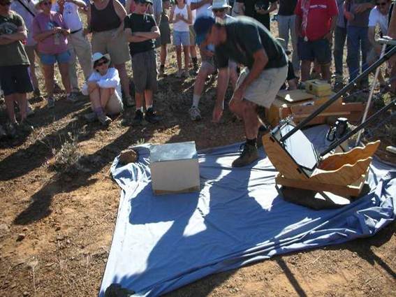
Origins of the folding design, culminating in my ZipDob. Here I am observing at the Oregon Star Party.
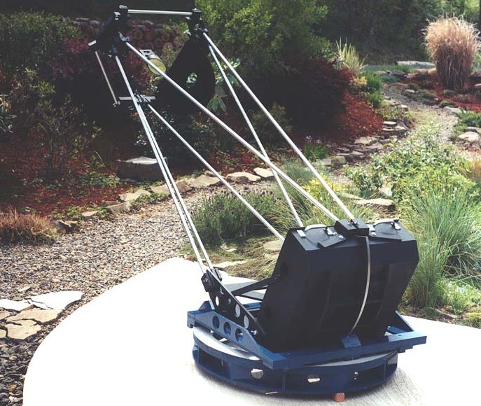
An alternative folding design: the scissor or spider Dob design
Collimating is the act of aligning all the axes of the optical elements. That means that the eyepiece axis as set by the focuser and the primary mirror axis are coincident or on top of each other. There are seven ways that break the symmetry of optical alignment that can be studied for little known telescope designs.
1. Primary mirror and diagonal. The most common is a combination of primary mirror and diagonal. The diagonal's angle is adjusted to aim the eyepiece/focuser's axis at the primary mirror's center then the primary mirror's pointing angle is adjusted to bring its axis in line with the eyepiece/focuser.
2. Primary mirror, diagonal and focuser. Sometimes the eyepiece/focuser's angle is adjusted with shims so that the focuser aims at the diagonal's center, thus all three elements are in play.
3. Primary mirror and focuser+diagonal as a unit. One option with a binocular telescope is to treat the eyepiece/focuser and diagonal as a unit that is tipped such that the eyepiece/focuser axis is aimed at the primary.
4. Primary mirror+diagonal as a unit. Another option with a binocular telescope is to adjust both the angle and position of the primary mirror and diagonal as an integral unit.
5. Primary mirror+diagonal as a unit and focuser. Sometimes the eyepiece/focuser is adjusted in angle and position as well as the primary mirror and diagonal in a binocular telescope.
6. Primary mirror alone. It is also possible to achieve collimation by adjusting the primary mirror in both angle and position. The primary mirror is first positioned such that its center is under the eyepiece/focuser axis, then the primary mirror is angled so that its axis is aligned with the eyepiece/focuser.
7. Eyepiece/focuser alone. By the same reason it is possible to achieve collimation by moving the eyepiece/focuser to and fro to center it on the primary mirror's axis then tipping the eyepiece/focuser so that its axis is aimed at the primary mirror's center.
The last two combinations are of particular interest in that the number of elements to adjust is but one, either adjust solely the primary mirror or adjust solely the eyepiece/focuser. This could prove conceptually and mechanically easier to achieve.
Imagine a focuser mounted on a plate that can slide up and down plus left to right. Many focusers have tip or angle adjustment screws but if not the movement can be incorporated into this focuser mounting plate. How convenient would that be - all the collimation screws right there together at the focuser.The diagonal can be coarsely adjusted initially in order to center the illumination cone or be attached to the focuser mounting plate so that it moves in concert with the focuser always keeping the illumination cone centered.
Or imagine the primary mirror in the standard cell that provides for tip or angle adjustments where the cell can be moved side to side and up and down. For example, the two point mirror edge support can be built on a plate with slow motion controls such that the mirror slides to and fro. Then all the adjustments are made right there at the primary mirror. The adjustments can be motorized too by adding small servo motors to the threaded rod adjustment screws.
Process is a deliberate approach to symmetry breaking or structure preserving changes using patterns to create beautiful, living telescopes. Simplifying, removing and combining are periodically necessary. This beauty or quality is objective in that we observe it in nature and agree when we see it.
The process is simple: do the one most important thing in the simplest possible manner while preserving symmetry and structure; then repeat. Knowing what is the one most important thing to do comes with a strong unifying vision or product design and many hours of practice. To create new, living designs, it is also vital to be both a designer and builder, to have experience building as many components of the telescope as possible, whether grinding the optics or coding the control software or designing and building the mounting.
John Dobson imagined that the compelling purpose of a telescope on a sidewalk was to show the sky to the public. That meant aperture for bright views through the eyepiece. He gave up tracking, precision construction and Pyrex full thickness mirror blanks in order to fulfill his vision. He substituted low cost hand carry-able plate glass blanks. He substituted hand pushed stiction bearings for clamp with fine motion assemblies. He repurposed concrete Sonotubes in place of aluminum and fiberglass tubing. He substituted binocular eyepieces for expensive telescope eyepieces. The culmination of all these changes was a new telescope design, compelling in its purpose. It’s dominated telescope design for the past 40 years. Night vision and electronically assisting viewing is opening a new evolutionary branch for sidewalk astronomy.
Future telescopes will look different than today just as today's telescopes look different than yesterday's. With patience and perseverance, you can create and build a new telescope design. Even a simple accessory like the Telrad can change amateur astronomy. As popular as the Telrad is, it is not an endpoint. Rob and Quinn Brown's Qinsight finder is the next evolutionary step. I invite you to join others and me on the journey of amateur telescope making.
A folding telescope unfolds to observe and folds backup to transport. The telescope bends over at the pivot points so that one part fits on top of or within another part.
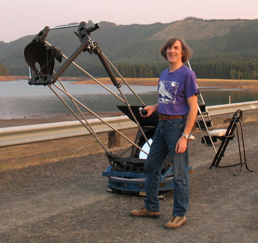
Here's my folding 13 inch telescope being unfolded during the 2011 Oregon Star Party Telescope Walkabout.
And here I am observing at night with the scope (image courtesy Craig Stott).
A sliding telescope slides in one direction to observe and slides back to transport. The telescope's parts slide over each other so that they fit within each other.
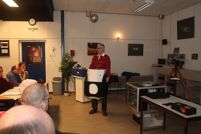
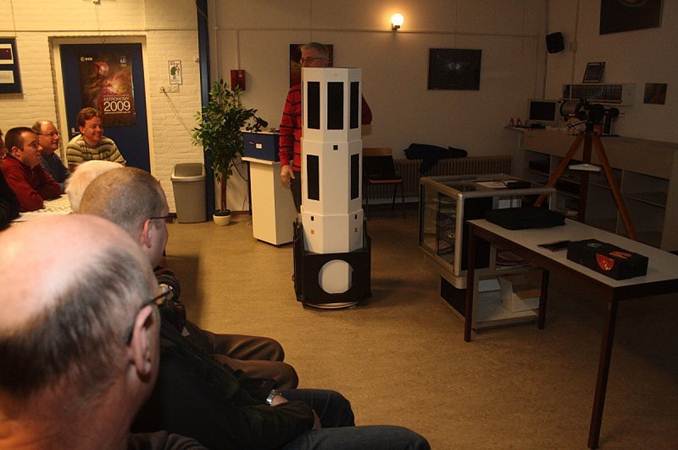
Here's Bert Bogchelman's scope that unfolds in seconds. Bert says, 'The telescope has a very quick setup, within a few seconds you can set up and collapse the tube. I have build a few truss Dobsons (I still have the word record smallest 8 inch) but I was sick and tired to set them up and even worse, to collapse them again after a long night of observations.But a full tube 12.5 inch Dobson has a huge tube and don't fit in a small car. So, I built this telescope and honestly, I am very, very happy with it. I have had a star party a few weeks before, and I was the only one with a big telescope who was able to look between the rain showers.
After the launch (3 seconds) you only have to turn the focuser and the finder from inside the tube to outside, and they snap into their places with magnets. The scope needs after setup only some minor collimation, like a truss design.
Some details:
Collapsed high: 61cm
Weight: 23 kg all-in (incl. the rockerbox), so you can carry the hole telescope in one.
12.5 inch F5 Strehl 0.94 mirror
Secondary mirror: 63 mm (20%)
2 inch Antarsi helical focuser
50 mm finder, right angle, correct view (Amici prism)
Images courtesy Jan van Gastel and Bert Bogschelman.
Any telescope that doesn't fold or come apart or requires assembling or connecting of parts such as truss tubes or constructing some part of the telescope is not a folding or sliding scope.
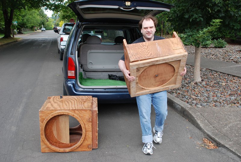
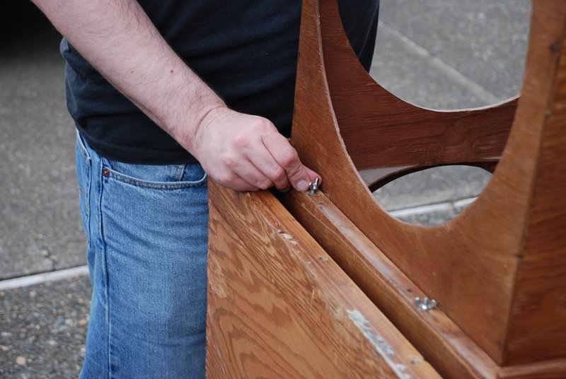
For example, here's my compact and easy to transport 6 inch. It's small enough to fit into the back seat of a small car with the rocker fitting over one end of the tube assembly. This scope stays fully assembled.
Here's a 6 inch scope that I took to Africa. The truss tubes come apart to fit into a backpack. It uses a single strut slide and pivot mount.
Travel scopes that pack tightly but take assembly time and effort. Typically one travels to a destination, assembles the scope and observes without further disassembly and re-assembly.
Here's Greg Babcock's 12 inch travel scope that he took to Argentina.
A folding scope offers extreme ease of use, is quick to setup, is easy to setup, is lightweight and takes up less room (camping gear occupies a much greater volume). The usability of a scope is not a single factor. A standard truss dob disassembles and stacks into a smaller volume. But the assembly takes effort. The usability is a combination of several factors: lightweight * compact travel size * ease of setup * speed of setup * aperture * absence of ladder. A folding scope attacks several of these usability factors: compact travel size, ease of setup and speed of setup.
The Prime Directive is to connect to the universe, contemplate our place in it and the meaning of it all (spiritual), gather observations in pursuit of a scientific study. A high usability scope can make us feel more connected.
Whatever design we pick needs emotional appeal: it must be alive, not feel cold or dead.
The basic technical challenge is to squeeze air out of the telescope by folding or sliding itself into a much more compact space.
The design and building challenge? Iterate, grow by small changes, favor fewer number of simpler ideas, build on ideas of others, make it beautiful, be a creator and craftsman.
I judge telescope designs by asking, 'Is it more useful than before, is it more exciting than before?' In the end, I develop for myself. Perhaps others will find my designs worth looking at. I studied Origami for folding inspirations along with other fields, particularly engineered products like folding bicycles. My goal is to squeeze air out of the telescope.
Here are my concept sketches.
Here is a study of Ken Lulay's folding design, adapted for a 13 inch f/3.0.
Google Sketchup is here
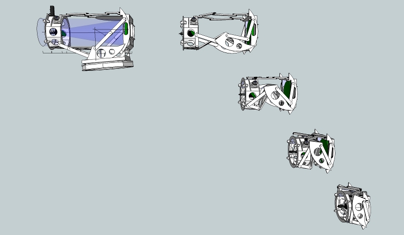
I also designed and built a folding spider design which takes up very little room.
Google Sketchup is found here
Another proposed way to fold a scope, this time using my 10.5 inch [27cm] F2.7
The Google Sketchup of my Zip Dob is here
For more on my 13 inch folding scope shown at the top of this page, go here
Michael Koch's folding ruler scope http://www.astro-electronic.de/reise.htm
Horace Dall's folding Cassegrain. (images by Peter Abrahams). Also check out a video interview with Horace at http://vimeo.com/28160854
Bob Cox's folding Cassegrain
Ken Lulay's folding 8 inch (on the left)
Victor Nikolashin's folding Cassegrain (1970 RTMC)
Carl Lancaster's articulated mast folding scope can be seen at
http://stellafane.org/convention/2013/images/scopes/scope27a.jpg,
http://stellafane.org/convention/2013/images/scopes/scope27b.jpg,
http://stellafane.org/convention/2013/images/scopes/scope27c.jpg,
http://stellafane.org/convention/2013/images/scopes/scope27d.jpg
Besides BertBogchelman's shown at the top of this page, here are other sliding scopes that I know of.
Pat Cannon's folding 17 inch. (Swayze's 40 inch is in the right background.)
Mark Yonkers, current owner, unfolding the scope.
The Teleport telescope, a commercial product, see https://www.pinterest.com/pin/tom-and-three-teleports--505529126919068460/ (image from the website).
Dale Sander's telescoping telescope.
Folding kayaks, see https://www.orukayak.com/
Folding bicycles, see http://www.bikefriday.com/ and http://www.designswan.com/archives/12-creative-folding-bike-design.html
Folding tables, see http://www.studiotoer.com/postable
The inventor of the reflecting telescope is even more difficult to pin down than the inventor of the refracting telescope which is still being debated today. There is a case to be made that the inventor of the reflecting telescope was actually Thomas Digges (1546-1595), not Sir Isaac Newton.
I imagine that humans have held up pieces of glass to the sky for millennium; after all Egyptians were making glass lenses 5000 years ago and there's evidence that they knew that curved pieces concentrated the Sun's rays to start fires. Perhaps the quality of the glass was so poor that not much could be seen. Only after glass dramatically improved in clarity during the 1500's was the telescope 'invented' in 1608, spreading like wildfire through Europe. Tantalizing historical fragments that could imply a telescope are well known: Aristophanes' play The Clouds, written in the 4th century BC, describes a 'transparent stone by which they kindle fire', a century later Euclid described refraction and reflection and Seneca the Younger (~65AD) wrote about lenses that magnified objects. The Camara Obscura was an important advance, first noted by the Chinese philosopher Mo-Ti in the fourth century BC and Aristotle in the third century BC then commented on by Anthemius of Tralles in the 6th century AD; later the astronomer Alhazen (1028 AD) correctly described the concept.
Writings from antiquity that might talk about telescopes include the Chinese emperor Tchuen hio, 2444 BC, who invented an instrument that gave a more distinct view of the heavenly bodies. The Babylonian Talmud, ~100 AD, describes a tube with which one could see a distance of 2000 cubits. Roger Bacon in 1268 AD wrote that refracting lenses can make distant objects appear closer and that print appears bigger when the lens is placed on the page. Not too many years later Italians began using bi-concave lenses to correct for loss of near-focus vision. Leonardo da Vinci essentially described a telescope using the mathematical rage of the day, catacaustic curves. Not knowing about the wave nature of light, he vastly underestimated the exactness needed for a good image. In the 1500's, with increasing frequency, more authors wrote about experiments with lenses.
However, we humans first had to discover that light comes from objects, not from emanations of our eyes as the Greeks suggested. Ibn al-Haytham (1017 CE, the Kitab al-Manathir or Book of Optics), considered the 'father of optics' proved that light comes from illuminated objects then travels to our eyes. He suggested that light exists independent of vision, a new idea. Ibn al-Haytham also said that light moved with a finite speed and that this speed varied as it moves through different materials - in other words, light bends as it travels through a lens. He also found that light moved in lines and that this light was not modified when crossed with other light. Ibn al-Haytham laid the foundation for Isaac Newton 700 years later to further explain light and to engineer eyeglasses, telescopes, microscopes and cameras. His discussions on perspective may have enabled perspective in Renaissance art.
By 1585, William Bourne writes, "... that the Glasse that ys grounde, beeynge of very cleare stuffe, and of a good largenes, and placed so, that the beame dothe come thorowe, and so reseaved into a very large concave lookinge Glasse, that yt it will shewe the thinge of marvelous largenes, in manner uncredable to bee beleeved of the common people." Here, largeness means focal length, not aperture. Bourne goes on, "Wherefore yt ys to bee supposed, and allso, I am of that opinyon, that having dyvers, and sondry sortes of these concave Looking Glasses, made of greate largeness,... yt ys lykely yt ys true to see a smalle thinge, of very greate distance, ffor that the one Glasse dothe rayse and inlarge, the beame of the other so wonderfully. So that those things that Mr Thomas Digges hathe written that his father hathe done, may bee accomplished very well, withowte any dowbte of the matter: But that the greatest impediment ys, that yow cannot beholde, and see, butt the smaller quantity at a tyme." Here Bourne refers to the use of long focal mirrors for greater magnification, and he finishes by describing the narrow field of view of a telescope. Something that we understand today, but would have been unknown in the era.
Bourne describes concave reflectors being coated on the rear surface of tin or antimony plating. Of course this gives ghost images, due to reflections from the front surface of the glass mirror.
Did Digges turn his telescope to the heavens thirty years before Galileo? In 1576 Digges writes in A Prognostication everlastinge, that the infinite universe is populated by stars "farr excellinge our sonne both in quantitye and qualitye...". And "Especially of that fixed Orbe garnished with lightes innumerable and reachinge up in Sphericall altitude without ende." The idea of an infinite universe appears to be new and the idea that there are stars far beyond what we can see with the unaided-eye suggests that he turned his telescope to the heavens.
Thomas Digges potentially connected with the Dutch spectacle makers like Lippershey as he was Muster-Master General for the English force helping Prince William fight the Spanish. As such he almost certainly met Jacob Metius's father. Jacob laid a competing claim to inventing the refractoring telescope on Oct 17 1608, Lippershey's having filed a patent claim on Oct 2. Between the two there is a report of a third Dutchman demonstrating a telescope on Oct 14. Perhaps these three got the idea from a common source, Juan Roget of Spain. For more on Roget, see the BBC story.
Paving the way. Historians, using AI to analyze 76,000 manuscripts in the 1500's, found that knowledge about the stars was widespread. They found evidence for the first proto-international scientific community, suggesting that science was not driven by lone wolves. Instead there was a wide involvement of many people. Textbooks printed in Wittenberg were widely copied throughout Europe.
In any event, once the word was out, the refracting telescope spread like wildfire throughout Europe. By 1609, Thomas Harriot (father of modern algebra, one of Elizabethan England's finest scholars) in England was drawing the Moon using a recently acquired Dutch refracting telescope four months before Galileo. Galileo began observing in 1609, rapidly publishing and promoting his revolutionary observations. Niccolo Zucchi mentioned exploring the idea of a telescope made from mirrors in 1616 but was unable to get a satisfactory image probably because of poor quality mirrors and the tilted optical path. This predates Galileo and Giovanni Francesco Sagredo who discussed mirrored telescopes in the 1620's.
Initially these instruments were called 'perspective tubes'. Galileo called them 'occhiale' or spyglasses. The name 'telescope' was first coined by the poet and mathematician Giovanni Demisiani at a banquet held by Prince Federico Cesi honoring Galileo in 1611.
Like Galileo, Sir Isaac Newton did not mind getting his hands wet with grit. He was likely first to polish with a pitch lap. And he wanted to prove his theory that white light was actually composed of a series of colors. Newton quickly ran into a series of difficulties: the metal mirror had to be extraordinarily accurate and the metal tarnished. The problem with Isaac Newton's 1672 telescope is that he got the design wrong, didn't build a good model and didn't disclose his technique for decades. He wrote that his design of a telescope with a spherical primary and elliptical plane mirror was fully adequate. But it was not, as we now know.
A telescope of his design of four foot focus was brought to the Royal Society's attention shortly after and was found wanting. The truth is that the spherical aberration present in his design rendered it unusable. He did not know how to make parabolic mirrors. Isaac Newton's model received much attention but ended up sitting on the shelf making not the slightest impact for half a century.
Prior to Newton's design, John Gregory devised an all mirror design in 1663 with a perforated parabolic mirror and a smaller curved mirror at the front of the tube sending light back down the tube. But the parabolic curves were far too difficult for opticians of his era and attempts to build the telescope failed.
In the same year as Newton's telescope, 1672, Sieur Guillaume Cassegrain, a sculptor (note the connection between his skill in casting metal sculptures and casting speculum mirrors), wrote of his design for a reflecting telescope, where Gregory's concave secondary mirror is replaced with a convex mirror. Today we judge Newton's invention as likely earlier that Cassegrain's, though it was hypocritical of Newton to criticize Cassegrain for using spherical mirrors. Regardless, the inventions of Newton and Cassegrain went nowhere.
These designs languished partly because neither Newton nor Cassegrain gave information on how to cast the mirror or how to grind and polish the mirror, though Newton did describe his polishing technique thirty years later.
Fifty years later, in 1722, John Hadley unveiled the first reflecting telescope worthy of the name. Hadley had figured out how to parabolize his speculum mirrors. His telescope was a six inch f/10 on a solid altazimuth mount with slow motion controls. He had eyepieces that gave powers up to 230x.
His telescope was tested against a refractor of 123 feet focal length and found to be its equal in resolution though somewhat dimmer. With John Hadley's telescope, observers could see the five moons of Saturn, Cassini's Division and even Saturn's ring shadow on the planet itself. Unlike his predecessors, Hadley shared his polishing and parabolizing technique. His method of testing has been used ever since, particularly in modern times by John Dobson.
Thomas Edison is considered the inventor of the light bulb not because he was first to demonstrate an incandescent light but because he developed the first practical and commercially viable electric light bulb. Karl Benz invented the automobile because he created the first true car though Leonardo da Vinci created the first designs. Galileo invented the telescope because he was first to grasp its astronomical potential and develop telescopes of increasing power even though Lippershey was first to publish and is accorded prime inventor status.
Similarly, John Hadley could be considered the inventor of the reflecting telescope. It may be more proper to speak of looking through a Hadleyian telescope than a Newtonian.
The result of Hadley's invention cannot be understated. Once John Hadley showed his telescope and shared how to build it with others, opticians began making parabolic primary mirrors and the era of the reflector truly began.
References:
The origins of the reflecting telescope, Colin A Ronan, Journal of the British Astronomical Association, vol.101, no.6, p.335-342
Louis Bell's The Telescope, McGraw-Hill, 1922
Robert Garfinkle's Luna Cognita, Springer, 2020
Henry King's The History of the Telescope, Charles Griffin and Co, 1955
Using AI, historians track how astronomy ideas spread in the 16th century, Science News
Scott Berkun's The Myths of Innovation, O'Reilly, 2007
Roma Agrawal's Nuts and Bolts: Seven Small Inventions That Changed the World in a Big Way
Peter Wise's presentation, 'A Brief History of the Telescope – From the Bronze Age to the Space Age', 2009
Actual field in degrees = field stop in inches / focal length in inches * 57.3
Focal length = focal ratio * mirror diameter
Eyepiece focal length / eye pupil = focal ratio
Mirror diameter = eyepiece field stop * eye pupil * 57.3 / (true field of view * eyepiece focal length * 25.4)
Telescope focal length = focal ratio * aperture (better known as, focal ratio = telescope focal length / aperture)
Eyepiece focal length = focal ratio * eye pupil (better known as, eye pupil = eyepiece focal length / focal ratio)
Eyepiece field stop = aperture * true field of view * focal ratio * 0.443 mm/in-deg
Eyepiece field stop = telescope focal length * true field of view * 0.443 mm/in-deg
Aperture * true field of view * eyepiece focal length = eyepiece field stop * exit pupil
Aperture = exit pupil * eyepiece field stop / eyepiece focal length / true field of view
Aperture = eye pupil * true field of view / object size
Magnification = aperture / exit pupil
Magnification = primary mirror focal length / eyepiece focal length
Magnification = apparent field / true field
Magnification = converging angle of the entrance cone of light / diverging angle of the exit cone of light
Etendue/luminance = aperture area * true field of view area (cm^2deg^2) = eye pupil area * eyepiece apparent field of view area (cm^2deg^2)
Focal ratio that maximizes etendue = eyepiece focal length / eye pupil, the focal ratio of the eyepiece and eye; further divide by any coma corrector magnification factor
For maximum etendue: aperture (inches) = 25 / object size (degrees)
Radiance flux (the ability to gather light then concentrate it) = aperture * aperture / (focal ratio * focal ratio)
Select an object from the catalog or enter the object total magnitude and object size as commonly given in catalogs.
The eye's background noise is about 26 mag/arc-sec^2. Objects fainter than this seem impossible to see. Objects near this threshold need an apparent size of 2-3 degrees to be detected. That's an area of 150x150 rods in the eye out of a total of 90,000,000. The brightest IFN (Integrated Flux Nebulae or galactic cirrus) near M81/82 is about 24.5 mag SB (Surface Brightness), the faintest IFN I've visually detected is about 26th mag SB.
These observations are in dark skies. Brighter skies lower the contrast (ratio of object+sky to the sky). It appears that the eye needs about 2% contrast or a 50:1 ratio (~21.75 mag sky background for a object of 26th mag SB 2-3 degrees in apparent size) such that these 150x150 rods create sufficient signal for our conscious brain. For example, a SQM reading of 20.74 (Bortle 4) lowers faintest detectable SB to 25th mag.
Object size makes a significant difference. A 14th mag galaxy when 2x2 arc-minutes size is 24.1 mag SB; if 4x4 arc-minutes size then the SB lowers to 25.6 mag. Doubling magnification reduces SB by 1.5 mag. Face on spiral galaxies are harder!
This calculator also shows the relationship between object visibility and light pollution as expressed by the Bortle level (see below). It appears that it takes a significant gain in aperture to make a practical difference and that increasing light pollution drags down all apertures rather proportionally. For example, tripling the aperture is worth one to two Bortle levels.
Search for an object from the catalog Select from matched objects
| Object name = | |
| Object apparent magnitude = | |
| Object size (arc-minutes) = | by |
| Sky background brightness = | |
| or use the Bortle Scale |
Vary aperture by x for the following chart
For a more in-depth treatment, see Human contrast threshold and astronomical visibility by Andrew Crumey
MPAS stands for Magnitude Per Arc-second Squared. MPAM stands for Magnitude Per Arc-minute Squared. I calculate using a circular area, not a rectangular area. Note that here object surface brightness is in magnitude per arc-second squared (MPAS). Many catalogs give object surface brightness in square arc-minutes. To convert from circular arc-seconds squared to circular arc-minutes squared, add 8.6 magnitudes to the MPAS value to get brightness in arc-minutes squared.
Sky background brightness is 21.5 MPAS for a dark site, 18.5 MPAS for a city site.
Detectable contrast for objects of large apparent size is 3-6%.
Very faint objects smaller than five degree apparent size can be impossible to see; the larger the apparent size the better as long as the apparent size does not exceed the eyepiece's apparent field of view.
The Greek astronomer Hipparchus in the 2nd century BC invented the magnitude system where the brightest stars are of 1st magnitude and the dimmest are of 6th magnitude. I suspect that this system was in use beforehand: it’s common for humans to divide groups of things into sixes and it would have been natural for us to call the brightest stars “first class”.
The magnitude system is logarithmic, not linear. This is no doubt because our eyes work logarithmically (or at least semi-logarithmically). For example a star that is 1 magnitude brighter is 250% brighter; conversely a star that is 0.1 magnitudes dimmer is 10% dimmer.
The first lesson then is that we cannot get hung up on linear percentages instead we must think in logarithmic magnitudes. This is difficult because discussions today are almost universally in percentages which is completely misleading. Illumination drop-off at the edge of the eyepiece? Stated in percentages (e.g. 15% sounds terrible) should be in magnitudes (e.g. 0.06 mag unnoticeable visually). Mirror coating reflections? Stated in percentages (e.g. 92%) are better stated in magnitudes (e.g. 0.04 mag loss). It is very difficult to see differences of 0.2 magnitude or less. And when the view is dimmed both object and background are equally dimmed leaving the contrast unchanged. Unless the view is grossly dimmed the unchanging contrast means that the object does not lose visibility. I will be using magnitudes just as charts and observing manuals.
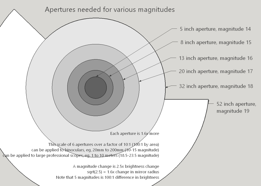
John Bortle created a nine level scale to measure sky background brightness. Level 1 is the darkest skies on Earth, while level 9 is inner-city skies. I use the average between Wikipedia and Clear Sky Clock. Here is a chart of the respective values:
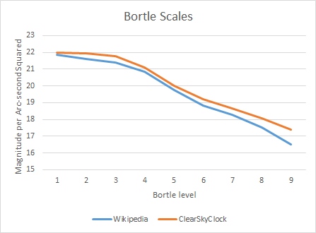
The first three Bortle levels concern themselves with what we typically call a 'dark sky', distinguishing between good, better and best skies. Bortle levels 4-6 represent suburban skies, a transition to urban skies that are covered by Bortle levels 7-9.
Do the Bortle levels, subjective as they are, evenly represent the range of sky brightness? Take a look at this graph of Bortle levels versus object detection. I used the Saguaro object database, a popular and vetted library of more than ten thousand objects, of which 8661 have surface brightness measurements or the surface brightness can be calculated. I use the object contrast multiplied by the apparent size in a 10 inch telescope to determine object visibility. As you can see the Bortle scale is nicely balanced.
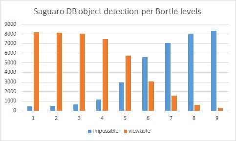
For extended objects things are not as simple as stars. For starters it is not possible to increase the surface brightness of an extended object by increasing the aperture. An example: take an object of 10 magnitude/ square arc-second as seen by the unaided eye at night exit pupil open to 7mm. Now look at the object through a 10 inch scope. If there is no magnification to the image the surface brightness will increase by the ratio of the scope's aperture to the eye's aperture squared or (10 inches / 0.3 inches)^2 =~ 1000x. However in order to fit all of the light from the 10 inch aperture into the eye's exit pupil we must use at least 33x. 33x will dilute the image brightness by 33^2 =~ 1000x so we are back where we started. In fact because of mirror coatings not reflecting 100% and the small obstruction caused by a diagonal the image brightness per area will actually be a little less than with the unaided-eye.
This leads to the interesting conclusion that the brightness of the sky glow as seen in the eyepiece is entirely dependent on the exit pupil. At a given location on a given night no matter the size of scopes if they are giving the same exit pupil then the sky glow brightness will be very similar.
Fifty years of observing deep-sky objects has shown that there is a strong correlation between contrast and object detectability. For an experienced observer a contrast of 6% makes for an easy detection while a contrast of 2.5-3% is quite difficult; contrast less than 2.5% is pretty much impossible. Interestingly, the object needs to be at least several degrees in apparent size for best detection results.
How well does the object's integrated magnitude match the object's surface brightness and size? I studied the Saguaro Catalog. The standard deviation between integrated and calculated magnitude is 1.3 magnitudes. So I use a 2 magnitude band to predict visual detectability when given an integrated magnitude. The following chart is based on my decades of observing experience using scopes up to 40 inches [1M] in size:
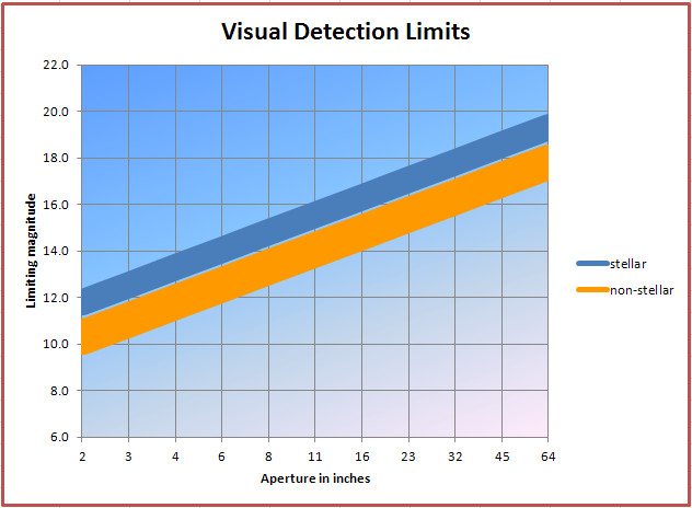
Notice that the lines are banded or thickened. You might fall slightly above or below these bands based on the factors discussed earlier. Beware of anyone or any calculator that states overly precise limiting magnitudes. These are at best guides and give a false impression that an object is either perfectly visible or perfectly invisible. Objects on the edge of visibility come in and out of view over a period of time. One night that object might be visible three times in a half hour (my standard for detectability). On another night it simply is completely invisible. On rare perfect nights not only can I detect it much of the time but there is detail too. Also if the galaxy or cluster or planetary is unusually large then the detection limit will suffer. Note that as aperture increases minor differences (say between a 20 inch and a 22 inch telescope) become insignificant even undetectable except for rare edge cases.
WHen considering surface brightness the limit appears to be the eye's background noise at 26 magnitudes per square arc-second. Here's a graphic based on my observations. When the object's surface brightness approaches the eye's limit, the object needs to be of sufficient apparent area, about 3 degrees in apparent size, to trigger enough rod cells (a minimum area of 150x150 rods or approximately 22,500 rods in total).
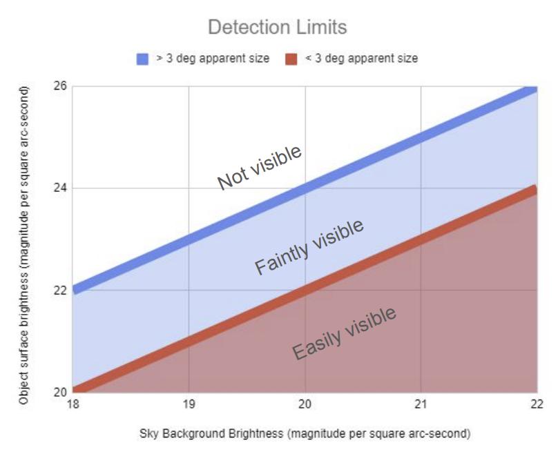
Here's a graphic that sums it all up:
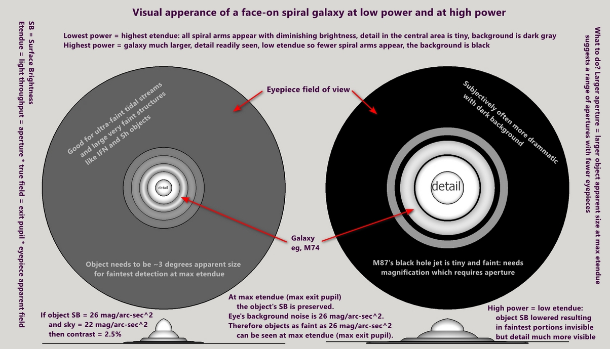
Here are two examples: a tidal stream (high etendue, low magnification) followed by M87's black hole jet (low etendue, high magnification).
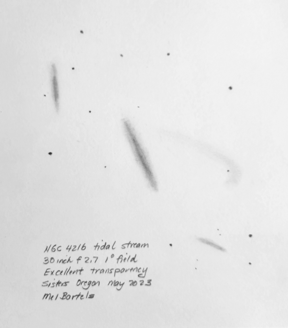
For more see "Praxishandbuch Deep Sky”.
And here is a telescope limiting magnitude calculator that takes into account quite a few conditions.
The surface brightness of familiar objects can be surprisingly low. For example, M31, the Andromeda Galaxy, has an averaged or smoothed surface brightness of 22.2 magnitudes per square arc-second; M51 the Whirlpool Galaxy a surface brightness of 21.7 magnitudes per square arc-second.
Increasing light pollution affects object detection. Bortle 4-5 skies have a surface brightness of 20 magnitudes per square arc-second, which lops two magnitudes off of the detection limit.
And magnification above the lowest magnification that fills your eye's pupil decreases object surface brightness by 1.5 magnitudes for each doubling of magnification. Keep in mind that many deep sky objects are small and require magnification to be seen. And that these objects are often brighter in their central region. The eye does surprisingly well keeping up with the decaying surface brightness as the view is magnified. A range of magnifications then is best for many objects.
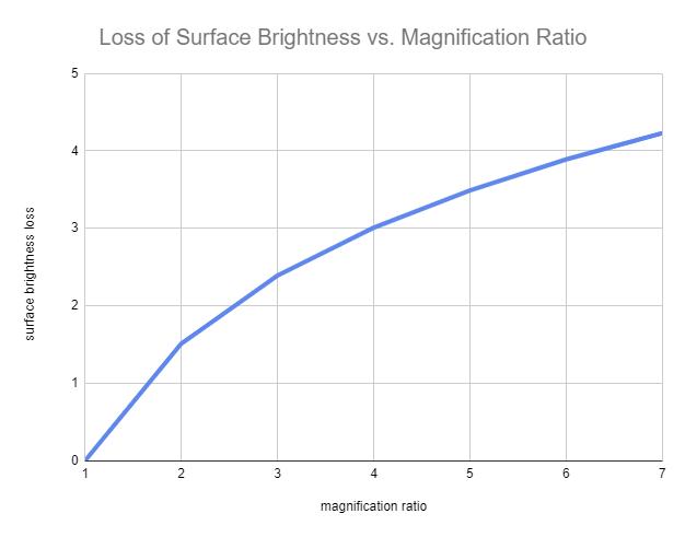
The light from an impossibly distant astronomical object goes through four, sometimes five, filters. They are:
A thought experiment: are stars more visible with a small exit pupil compared to a large exit pupil?
Consider the beautiful star cluster, Carolyn's Rose, NGC 7789. In a 6 inch [15cm] at 1mm exit pupil, or 130x, the cluster is a beautiful ephemeral cotton ball of stars. Let's increase the exit pupil to 6mm, keeping the magnification unchanged. This means increasing the aperture to a 36 inch [91cm]. Here the cluster is an intense collection of stars, many with reddened hues. The stars are much brighter and there are many more to be seen in the larger scope. So we conclude that keeping magnification unchanged, increasing the exit pupil increases the brightness of stars.
If aperture is held constant then limiting magnitude increases with increasing magnification, that is, fainter stars are visible with the smaller 1-2mm exit pupil compared to the larger 6mm exit pupil.
Dividing object visibility into six categories: very easy, easy, moderate, difficult, very difficult, and impossible, I investigated how much the aperture needs to be increased when comparing Bortle level 1 to level 4 skies.
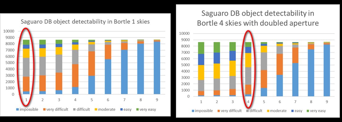
We see that a scope of size 'x' in dark skies (Bortle 1) performs roughly as a scope of size '2x' in modestly light polluted skies (Bortle 4). This is true in a coarse sense for all object types. Put another way, increases in aperture make more of a difference in object detection in darker skies compared to light polluted skies. In heavily light polluted skies, aperture must be dramatically increased to make a practical difference not to mention that low magnification / high etendue views are precluded. Generally speaking, darker skies are more important than aperture. Each person will have to answer the question of how far to drive with what size of scope. One approach that this suggests then, is to make most observations in suburban skies, occasionally traveling to dark skies to finalize the observations.
Seriously. It's happened to the best of us, leaving a stop-down off-axis mask in place, wondering why the views are dim or incredibly murky, wondering why that object cannot be found.
For deep-sky objects, dark adaptation is essential. Benefits continue to accrue for hours: the difference between 20 minutes of dark adaptation and two hours is 1/2 a magnitude.
Averted vision works best if you know where to aim your eyes in the field of view. Here's a chart to help.
Get a dark sky or nebula filter. These filters really help to make subtle detail more noticeable. A filter is more important than aperture because a nebula filter increases contrast more so than aperture. Try different filters, try different filters with different eyepieces.
I am constantly surprised by the view at very different magnifications. However, going past what seeing allows that night is always painful. What is the seeing limit? Only way to know for sure is to run through your sequence of eyepieces.
Eye shields that block extraneous light, even natural dark-sky light, are amazingly effective. Here's an example:
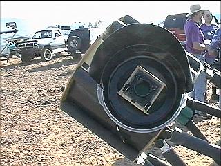
Look down at the dark ground as much as possible - your night vision is affected deleteriously by looking up at the sky for too long of periods of time.
Take breaks, drink some water, remember to blink. Comfort at the eyepiece is worth a half magnitude. Get an observing chair, rotate the focuser to a better viewing angle, set up a small table next to you for your eyepiece case, tool chest and tablet or phone. Make it easy on yourself.
Unless you have astigmatism, try looking without glasses. Refocusing the eyepiece will take care of near and far sighted eyes.
Position the eyepiece as far outward as possible then focus inward until the stars just come to focus. This is the most relaxed, infinity focused position for your eye. Moving the focuser inward results in a slightly more magnified view, but at the expense of focusing your eye close-in, which is tiring.
Your eye needs to be centered over the eyepiece and looking down its axis. You also need to position your eye at the correct distance from the eyepiece. Some eyepieces come with a rubber cup that places your eye at the correct spacing above the eyepiece. You can look up the eye relief spec for the eyepiece to get a guide. In the field move your eye away and towards the eyepiece. Slowly move your eye inward until you can see the field stop - the black edge of the field of view.
Move your averted vision zone around the field of view as you desire. Look for a bit here, look for a bit there (your scan pattern). Do not fixate on the center of the field. For one thing, this mis-places the zone of averted vision towards the bottom of the field, for another thing, it is not possible to prevent the eye from moving. Several times a second, your eye jumps (called a saccade). Even between saccades, the eye jitters. Finally, if you stare too long at a single point, objects will literally begin to disappear from your view. In a sense, seeing is reflective: if the eye didn't move then little could be seen. Move the scope in addition to your eye: this helps to 'pop' objects into conscious visibility.
Observer experience is worth 2 magnitudes (I have a series of sketches of M31 from childhood onward showing my increasing ability to see). There is no substitute for hours at the eyepiece. How often do you observe a week? What can you do to increase your observing hours? Make the telescope more portable, join others observing. Aim to observe one to two times a week on average. Malcolm Gladwell's book, "Outliers", states that thousands of hours of practice are necessary to become an expert. How many hours do you think that Stephen O'Meara has observed? How many have you?
In particular we want to build on our visual memories of previous observations stretching through the years. I practice by sketching charcoal drawings of nature, blurring digital images then sketching them, studying the grays in clouds and looking into the dark grays of landscapes and so forth. How we draw influences what we see too.
Time at the eyepiece is worth a magnitude (objects gradually become recognizable or detectable over a period of time and then they fade after a prolonged period of continuous observing). A few minutes brings awareness to detail that's thrilling and satisfying but do not stop there. More awareness and detail comes after observing for an hour or more on an object. The most difficult objects are only there part of the time. The seeing will stabilize and your concentration will be at your peak with your eyes paying attention to the proper place in the field. My personal standard is that I have to see the object or detail in question three times over a 20 minute session to say that I 'saw it'.
Knowing where to look and what to look for worth a magnitude.
The vast majority of observers are truthful to themselves, knowing or not caring that they will fail to convince doubters. It's all subjective. Look at sketches by observers. Each observer tends to notice or emphasize certain features. If I see something, great; if I don't, that's great too. Knowing that it is beyond my observational powers is worthwhile too. I certainly add the negative results to my lists of "impossibles" to go after on those rare nights of perfect transparency when I find myself under the darkest skies.
The variation in appearance on different nights with different transparency and seeing through different eyepieces can be striking. M1, the Crab Nebula, can look quite different from scope to scope and night to night.
Occasionally an object will be plotted in the wrong location or you will look in the wrong spot. You should never detect something that is not there. This is a great check on your observing skills. For example, many years ago one of the Palomar Globular Clusters was plotted incorrectly in the first edition of Uranometria (the negative/positive sign for Declination had been reversed, resulting in a 20 degree positional error). I spent hours looking for this Palomar Cluster with my 24 inch over two nights. Never could spot it. Importantly, I never fooled myself into thinking that I had spotted it. This happens from time to time and serves as a great check.
Let's dispense with the myth that aperture makes all the difference. One of the greatest observers of all time, Stephen O'Meara, uses a 5 inch [13cm] telescope. I've seen expert observers work their magic with telescopes regardless of the telescope's aperture and quality. I've never seen an increase of aperture turn a so-so observer into a great observer. I have witnessed amateurs regrettably leave the hobby after quickly jumping up in aperture or purchasing expensive high-end telescopes, their dreams unfulfilled. A common progression goes like this: entry level middle of the road scope, then a larger aperture scope followed ultimately by the realization that aperture does not make the observer followed by stirring a smaller scope into the mix. Advanced amateurs favor telescopes optimized for their favorite objects: giant telescopes for clusters of galaxies, long focal ratio scopes for lunar and planetary, very portable scopes for traveling to dark skies.
To an experienced observer, transparency is everything. A wonderfully transparent night renders aperture insignificant. Every telescope becomes a winner on an exceptional night. Learn to look for signs of excellent transparency during the daytime such as blue sky right up to the edge of the Sun (mask the Sun with your hand), jet trails (the trails should be short, not stretching across the sky, indicating a dry upper atmosphere), and clear sunsets and sunrises.
I suppose we all lust after that model '700' instead of the '500' model that we have. It's natural to want the best; we all strive for it, but will it magically endow you with the experience of hundreds of hours of observing time? At star parties I tend to gravitate to the humble observer with the used looking telescope, maybe a bit scuffed up from many nights of use, with optics of decent quality. For example, thanks to the Denomination Bias, amateurs will pay more money for a 1/12 wave mirror than a 1/10 wave mirror, yet the difference between these two ratings is an undetectable 1/60 wave. During a night of perfect seeing and incredible transparency at the 1997 Oregon Star Party, I took time from observing at 2000x, even 6000x, to check out the views in various scopes. Even 'ordinary' scopes gave astonishing views, demonstrating that transparency and seeing are near 'everything'.
Seeing the object in a larger scope then returning immediately to your smaller scope can result in a half magnitude gain. Swing over to a BBBB object (Jerry Oltion's Big Bright Beautiful and Bold) after a couple of hours of going after one or two very faint objects. That BBBB object will look more glorious than ever before.
Psychological factors are as important as physical factors such as sky darkness, object brightness, aperture and magnification.
What we consciously see is heavily influenced by our expectation of what is to be seen and of our training. These expectations and training can be said to form a bias. We want to ensure that training and knowledge of an object's particulars helps us see more but does not fool us. For example, I practice drawing M51, the Whirlpool Galaxy, with small apertures. The galaxy does not look spiral and the connecting spiral arm to the companion galaxy is hardly noticeable.
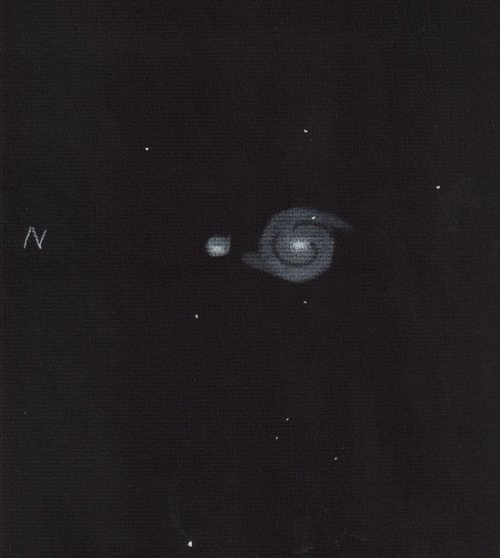
Tricks of the eye should not stop us. It is OK to be fooled. For example, very faint very close (almost touching) double stars can mimic tiny elliptical galaxies in a field of galaxies, suggesting a cluster of galaxies where one does not exist. For example, looking above NGC4565 past NGC4562, we see what looks to be a galaxy cluster. But several of the IC objects are actually very faint very close double stars. The fact that they have IC designations means that I am not the only one fooled by the scene.
Speaking of being fooled, if you watch magic tricks then the sky will be more vivid and you will see more that night through the telescopes. It is about pushing aside our preconceived notions that hush our ability to see what is really there.
In the dark evening sky, take a pair of binoculars and after dark adapting, compare the view through one eye versus both. Two eyes together reveal greater contrast and fainter objects.
For impressions of views through binoscopes, see my binoscope designer.
Observers at the 2022 Golden State Star Party (GSSP) report that a good NV device with a silvered 30 inch mirror produced stunning views of M16 and the Pillars of Creation. They report that the view looked just like this photo with the 4 meter Mayall telescope (NOIRLab) except that it was in real time.
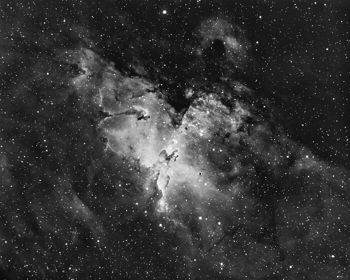
Observing later through Howard Banich's 30 inch f2.7, the twin of my mirror, I am blown away with the Night Vision device's views. Take the Pelican Nebula, for example. Visually I barely make out the two black lanes; with the NV the edges of the lanes glow as well as the heads! I grabbed an image from the Wikipedia page then reprocessed it to look like the view through the NV device. Image attribution: By Urmymuse - Own work, CC BY-SA 4.0, https://commons.wikimedia.org/w/index.php?curid=107860278
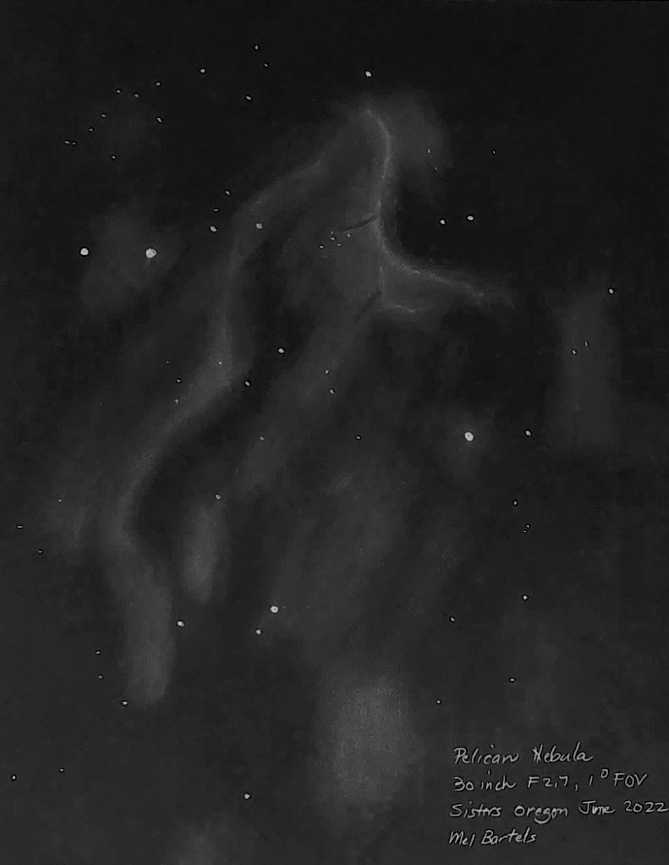
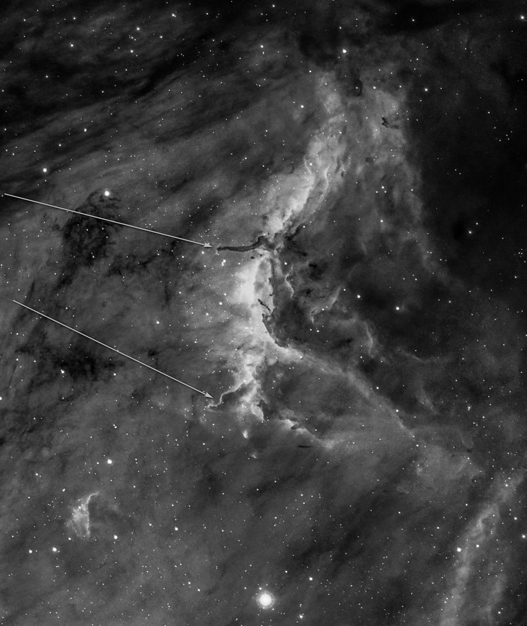
Planning to use a coma corrector? select magnification factor
not to exceed eye pupil of mm
Sort 'Select eyepiece' by Sort eyepiece table by old eyepiece list new eyepiece list
| Select eyepiece | Manufacturer | Type | FocalLength | FieldStop | Field | ExitPupil | TrueFOV | MagX | PerInch | Res | MagLimit | Etendue | ComaAtEdge |
Thanks to Don Pensack for eyepiece data which I combined with my data for older eyepieces into a new list.
A range of magnifications is key to using a telescope properly.
Magnification is the ratio of the apparent size to actual size of an object. For example, looking through a magnifying lens the spider appears three times bigger. That's a magnification of 3x.
Magnification depends on telescope focal length and eyepiece focal length. Calculate magnification by dividing the telescope focal length by the eyepiece focal length. For example, a 6 inch or 15cm telescope of 48 inches focal length used with a 9mm eyepiece yields a magnification of 48 inches * 25.4mm per inch / 9mm = 135x.
Astronomical objects are very far away and very faint. Both magnification and aperture are needed to view and image objects.
Astronomical objects are either point sources like stars, too small in diameter to ever be resolved in a telescope, or extended sources like nebulae.
There is a practical limit to both lowest magnification and highest magnification.
The lowest magnification is simply the ratio of the telescope's aperture to the eye's dark adapted pupil. The lowest possible magnification for a 6 inch or 15cm aperture is 6 inches * 25.4mm/inch / 7mm eye-pupil = 22x.
A useful highest magnification is the magnification where the eye's resolving power is fully utilized. A telescope's resolution is limited by interference caused by the aperture. The interference creates a disk of light surrounded by ever fainter rings of light. The radius of this Airy Disk is ~ 1.2 times the wavelength of light divided by the aperture. For a 6 inch or 15cm aperture scope the Airy Disk is 0.75 arc-seconds. The eye can resolve 120 arc-seconds. The magnification that matches the eye's resolution to the telescope's resolution is 120 arc-seconds divided by 6 inches aperture or roughly 27x per inch of aperture (roughly 68x per cm of aperture).
Some observers prefer up to twice this amount so that the eye isn't strained (54x per inch of aperture or 136x per cm of aperture).
Magnification above this is termed empty magnification: the object is made larger but nothing more can be resolved. In certain cases such as double star observing, increasing magnification above this amount makes measuring the separation between the stars easier, but otherwise the image becomes softer, fuzzier and displeasing to the eye.
Shimmering in the atmosphere, called seeing also limits magnification. If the jet stream is overhead or the upper atmosphere otherwise disturbed, magnification can be limited to 250x regardless of aperture. Steadier nights allow for increased magnification. The number of nights where 500x or higher can be employed are few and highly prized by observers. Nights where 2000x and higher can be used come very rarely. For example see The Night of 6000x at the 1997 Oregon Star Party. For more on seeing and the atmosphere, see my article on atmospheric turbulence.
Stars (other than our Sun) are so far away that they are not resolvable regardless of magnification. They remain point sources. Extended objects (Moon, Sun, planets, nebulae, galaxies), however, are resolvable. As magnification increases, their light is spread over a larger area, decreasing brightness at any single point. The Moon, Sun and planets are so bright that increasing magnification doesn't consign them to invisibility. Nebulae and galaxies are a different matter.
Let's use the Andromeda Galaxy, visible as an elongated smear in dark skies to the unaided-eye. It's about 3x1 degrees apparent size with an integrated or overall magnitude of 3.5. The galaxy has an average surface brightness of 22.2 magnitudes per arc-second square. Let's use our 6 inch, 15cm, aperture at lowest magnification of 22x. At 22x the Andromeda Galaxy now appears 66x22 degrees in size and will comfortably fit within a 80 degree field of view eyepiece. The telescope brightens the galaxy by the ratio of the square of the telescope's aperture to the eye's aperture, or (6 inches of aperture * 25.4 mm/inch / 7mm eye-pupil) squared or 484 times. But the magnification of 22x decreases the object's brightness by the identical 484 times amount, leaving the apparent average surface brightness unchanged at 22.2 magnitudes per arc-second. Yet the view through the 6 inch is immeasurably richer. Why?
Balancing aperture with magnification is as if a rocket ship takes us 22 times closer. We see more detail and the object overall is much brighter. But fly too close and the eyepiece can no longer fit the object into the field of view. Using the same telescope at increasing magnification means more detail at the cost of brightness.
Lowest magnification is given for 7mm and 5mm pupils, older people's eyes being closer to 5mm. Magnifications greater than 250x may be limited by seeing conditions.
| Aperture | Lowest Mag | Lowest Mag | Highest Mag | Highest Mag |
| inches | 7mm pupil | 5mm pupil | doubled | |
| 0.3 | 1 | 1 | 7 | 15 |
| 1 | 4 | 5 | 27 | 54 |
| 2 | 7 | 10 | 54 | 108 |
| 4 | 14 | 20 | 108 | 216 |
| 6 | 22 | 30 | 162 | 324 |
| 8 | 29 | 40 | 216 | 432 |
| 10 | 36 | 50 | 270 | 540 |
| 13 | 45 | 63 | 338 | 675 |
| 14 | 51 | 71 | 385 | 770 |
| 16 | 58 | 80 | 432 | 864 |
| 18 | 65 | 90 | 486 | 972 |
| 20 | 72 | 100 | 540 | 1080 |
| 22 | 79 | 110 | 594 | 1188 |
| 24 | 86 | 120 | 648 | 1296 |
| 25 | 90 | 125 | 675 | 1350 |
| 28 | 101 | 140 | 756 | 1512 |
| 30 | 108 | 150 | 810 | 1620 |
| 36 | 130 | 180 | 972 | 1944 |
| 40 | 144 | 200 | 1080 | 2160 |
| 48 | 173 | 240 | 1296 | 2592 |
| 60 | 216 | 300 | 1620 | 3240 |
Three examples...
Saturn. Since Saturn is a planet, select for highest useful magnification for your telescope, given seeing conditions. For example at my home I am often limited to 250x, sometimes I can get up to 500x, occasionally I can reach 1000x before the image turns fuzzy thanks to seeing.
North American Nebula. The NAN is an extended wide field object, spanning 120 arc-minutes.
Compute the highest magnification such that the entire object plus a border fits into the eyepiece. For this we need to know your eyepiece's apparent field of view.
Dumbbell Nebula. This planetary nebula is a favorite of observers. Its size is about 8 arc-minutes. Enter its size in the calculator above. The calculator will give a value of 240x-600x depending on the eyepiece's apparent field of view. The calculator will also give an aperture value far greater than your telescope. In this situation, use the largest aperture you have, setting its magnification to the calculated amount.
If the object is too faint, then use a slightly lower magnification. If the object is too fuzzy because of turbulence in the atmosphere or perhaps because the telescope is performing poorly, then lower the magnification. Be careful to not over-magnify the object such that it overfills the field of view. This can cause a faint object to disappear.
Here is a table of magnification and aperture for objects of different size. The aperture is based on a 7mm eye pupil. For 5mm eye pupil, increase magnification by 1.4 and decrease aperture by 1.4. Magnifications greater than 250x may be limited by seeing conditions.
| Eyepiece apparent field of view | ||||||
| 60 degrees | 80 degrees | 100 degrees | ||||
|
Object size arc-minutes |
magni- fication |
aperture inches |
magni- fication |
aperture inches |
magni- fication |
aperture inches |
| 180 | 16x | 5 | 22x | 7 | 27x | 8 |
| 60 | 48x | 14 | 64x | 18 | 80x | 23 |
| 20 | 64x | 18 | 85x | 24 | 107x | 30 |
| 5 | 224x | 63 | 299x | 83 | 373x | 104 |
The strategy is to select the highest magnification that frames the object in the eyepiece's field of view, subject to seeing conditions and telescope capabilities. Then select the largest aperture available. Starting with a given aperture, select for the highest magnification that frames the object, subject to seeing. If the object is invisible, then try a lower magnification. This rarely happens. Much more common is a failure to properly frame the object. Use filters, go to dark skies and improve your observational skills.
Should you ever select for less aperture? That's equivalent to stopping down the aperture to improve the view. Stopping down by using an off-axis mask to reduce the deleterious effects of bad seeing helps. Stopping down to improve deep-sky views does not help. While objects can be detected at diminished apertures, there is a general loss of detail. See my results at Is aperture king?
As long as you can select for the largest aperture, you are in telescope mode. Once aperture is constrained, you are in eyepiece mode. Well-equipped amateurs who have a number of eyepieces should also consider equipping themselves with a range of apertures.
Note that wider angle eyepieces allow for greater aperture.
One thing's for certain: I've bought and sold many eyepieces!
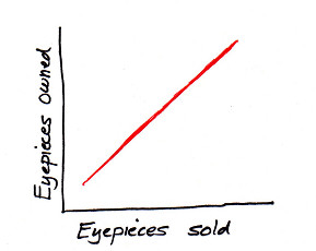
Distance to object is
The TeleVue P2 2 inch coma corrector requires an additional 3/4 inch [19mm] inward travel and moves the focal plane outward 1 13/16 inches [46mm].
I place the primary mirror focal plane 1 15/64 inches [31m] above focuser block top and since the focuser's compression ring is 3/8 inch [10mm] thick, the primary mirror focal plane is positioned 55/64 inch [22mm] above the focuser's compression ring top. This results in the primary mirror focal plane being positioned 35/64 inch (or about 9/16 inch) [14mm] above coma corrector barrel bottom.
I use 5/16 inch [8mm] in-travel for observers who are strongly near sighted. Therefore I design the primary mirror's focal plane to be about 9/16+5/16 = 7/8 inch [22mm] above the racked in focuser top.
Optically the coma corrector needs to be positioned at the designed distance from the primary mirror and its focal plane. However, for very fast telescopes F3.0 and faster where the eyepieces' spherical aberration affects image quality, the coma corrector can be re-positioned to minimize spherical aberration while not materially affecting the coma correction. A mirror that is cooling in the evening that exhibits overcorrection can be brought back to proper correction by slightly altering the position of the coma corrector. Small changes in the coma corrector's position significantly alters the spherical aberration while hardly affecting the cancellation of coma. Using the star test I estimate 1/8 wavefront change for each one letter change of the P2's tunable top.
This calls for a new concept in focusing where two focusers are needed: one of limited range to adjust the position of the coma corrector and the other to adjust the position of the eyepiece. With the P2 I focus in three stages. First, I use the focuser to roughly position the P2, secondly I use the P2's tunable top to optimize the eyepiece position, then finally I return to the focuser to bracket the focus a couple of times until I can precisely find the center of focus.
| Maximum charted magnitude loss = | It's very difficult to see light loss less than 30% or 0.3 magnitude. |
| Or enter your own diagonal size(s). | |
|
Include focuser barrel vignetting? |
|
The chart displays the loss of light from the eyepiece field of view's center to edge. Smaller diagonals obstruct less light, degrade detail less, but suffer from loss of light to the field's edge. Also important is the total amount of light reaching the field. These charts will help you make the best diagonal size choice for your situation. For more, see the discussion below.
| Results: |
Include any P2 intrusion?
| Off-axis mask results: |
For the complete picture, the chart includes light lost from the diagonal obstruction. Larger diagonals improve off-axis illumination but cost light across the entire field.
Use the magnitude scale; avoid percentages of illumination: the eye responds logarithmically, not linearly. It's a mistake to be upset over a 5% light loss when in fact from the eye's perspective the light loss is an imperceptible 1/20 magnitude.
The default diagonal to focus distance is set for a low profile focuser. Low profile focusers shorten the diagonal to focus distance enabling a smaller diagonal. Low profile focusers are not just for fast scopes where the bottom of the focuser barrel cannot be allowed to vignette or clip the light coming in from the mirror's edge to the eyepiece field's edge. Taller focusers have two benefits: the longer focuser barrel implies greater resistance to bending and play and the bottom of the focuser barrel can act to block some stray light.
Coma correctors like barlow lenses are best thought of as eyepiece accessories. Just reduce the desired field size by the coma corrector or barlow's magnification factor. Ignore the change in the focal plane. For example, if the coma corrector magnifies 15% then reduce the desired field to illuminate by 15%. Vignetting is not an issue down to F2.6 for pupils 7mm and smaller.
I find light loss of less than 0.3 magnitude hardly noticeable. For extended objects where both the background and object drop equally in magnitude, the contrast or ratio is unchanged, meaning that the eye's ability to detect the object remains largely unchanged. For instance, compare a 10 inch to a 12 inch telescope - the magnitude drop is 0.4. I can detect this difference when comparing views on borderline objects. A drop of 0.5 magnitude or more is not readily detectable on brighter objects. However, the difference between a 10 inch and a 11 inch telescope is much smaller at 0.2 magnitudes and not readily apparent.
An object's detectability depends on contrast between object and sky, apparent size of the object and the object's brightness. The contrast is the ratio between the object's brightness per area (typically one arc-second squared) added to the sky background brightness that is in front of the object and the sky background brightness adjacent to the object (contrast=(object+sky) / sky). When a star or extended object is dimmed as it approaches the edge of the field of view, so is the sky background. Contrast remains the same. Experiments that I have conducted show that the object's detectability is not diminished as much as the raw magnitude loss suggests. Besides, if critical detection is required, then the object can be brought to the center of the field. Read more on visual detection and limits at the eyepiece.
Diagonals act to lower contrast for certain spatial frequencies. A one-third obstruction, a much larger ratio than the customary visual Newtonian uses, lowers contrast to that of a 1/14 wave RMS system.
In particular I recommend analysis on the effects of central obstruction and optical quality like Damien Peach's at http://www.damianpeach.com/simulation.htm.
Diagonals are offset because the diagonal's edge closest to the primary mirror has further to travel to focus. Commonly the diagonal is positioned further away from the focal plane and closer to the primary mirror, in effect sliding the diagonal along its major axis. Here the diagonal intercept distance does not change.
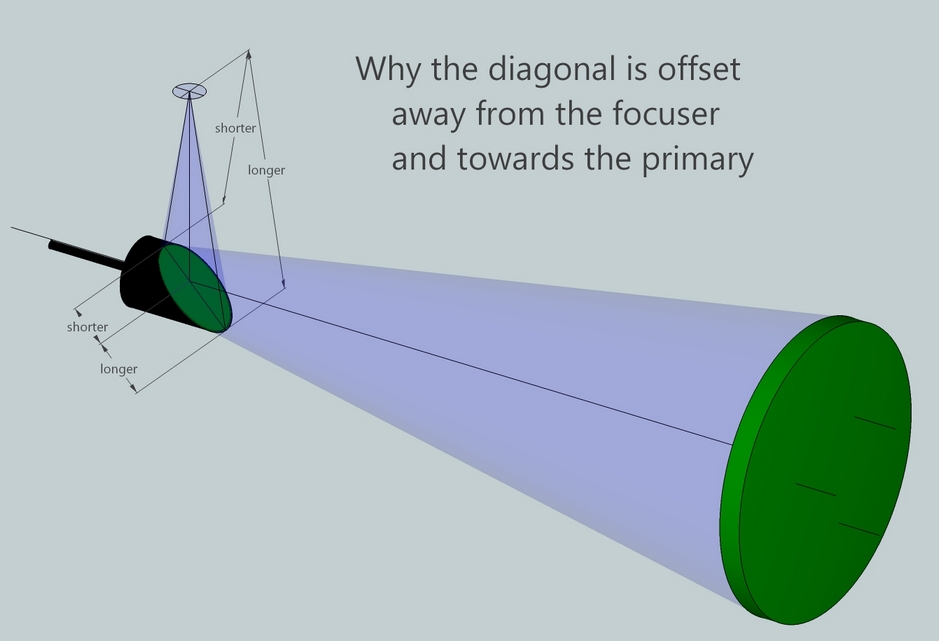
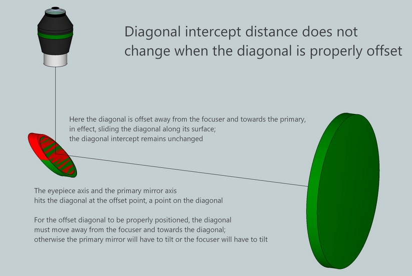
I calculate four different offsets which vary depending on perspective.
In other words, the offset moves the center of illumination (there are at least four 'centers' as noted) towards the field center. Even if the primary mirror's perimeter cannot be seen in its entirely this hardly affects resolution and can be seen as a matter of the center of illumination vis-a-vis the eyepiece's center.
When designing a telescope I select an average offset based on focal plane center and balancing illumination at the field edges. I mark the diagonal at this offset with a very fine point permanent marker, then use a laser collimator to align upper end, focuser, eyepiece, diagonal and primary components, with the goal to center the eyepiece axis and primary mirror axis on each other. For example, see how I built the focuser adapter assembly for my 30 inch [76cm] F2.7 telescope. In practice it is impossible to visually detect these different offsets and digital imagers will flat field anyhow.
Three situations to consider:
The MTF (Modulation Transfer Function) curve is an excellent way to understand the impact of obstructions. Here's Thierry's detailed discussion.
Far more impactful on resolution than the central obstruction are:
This was made evident on a night of perfect seeing at the Oregon Star Party. The central star of the Ring Nebula was a perfect dot at 6000x in my 20.5 inch F4.8 telescope. I took a trip around the telescope field. Even lowly Coulter scopes with their 'average' mirror quality gave surprisingly good images, revealing low contrast features on planets. The impact of seeing is far more impactful than central obstruction.
I wanted the most from my new 14.25 inch [36cm] Horseshoe mounted reflector. Conventional wisdom of the era was that a reasonably sized secondary of 1/5 to 1/4 the diameter of the primary mirror was fine, that there was little benefit to going to a smaller secondary. Some people though were agitating that secondary size mattered a great deal, that I would only be getting the very best images if my secondary was small. Maybe there were onto something, maybe convention wisdom was wrong.
Worried that I might not achieve the very best images, I designed a nifty self-collimating quick-mount secondary holder so that I could swap back and forth between two diagonals: the smallest possible diagonal for planetary and lunar imaging and a larger diagonal for deep-sky use. What resulted was a surprise.
Here is the 1.83 inch diagonal in its self-collimating quick-mount holder. The large diagonal was a 2.60 inch. I built a motorized slide focuser with a single straight stalk diagonal holder. The 1.83 inch
diagonal was 1/8 the diameter of the 14.25 inch primary and the 2.60 diagonal was 1/5 the diameter of the primary.
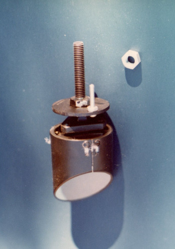
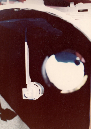
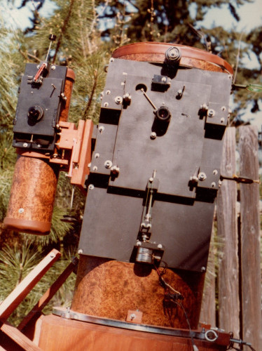
In the 1970's, besides doing a great deal of visual observing, I was into eyepiece projection photography of the planets and cold-camera long exposure astrophotography.
I compared the two diagonals visually over many nights observing the planets with colored filters. I compared hundreds of highly magnified eyepiece projection negatives and slides. For deep-sky I visually counted stars in a small region of M13, the great Hercules Globular Cluster.
After a number of months I was forced to conclude that visually there was no noticeable difference on planetary images and no difference in star counts on M13. To my utter surprise, after months of photographing Jupiter and Saturn, I was forced to concede a very slight advantage to the 2.60 inch diagonal, the opposite of my expectation. How could this be?
Could the 2.60 inch diagonal be covering a bad center zone of the primary mirror? No, the mirror is without zones.
Could there be alignment or vignetting issues? No, I checked again and again.
Could there be a difference in optical quality of the diagonals? Perhaps the 1.83 diagonal had a slight edge problem. After all, only when a diagonal is absolutely minimally sized will its edge be used to form the image at the center of the field of view. I was forced to conclude that this was the most likely reason.
The real message though is that closely sized diagonals do not make a discernible difference in visual performance. Intrigued, I set about making larger masks of 1/4, 1/3 and 1/2 the size of the primary. Over several nights I saw a consistent result: the 1/4 mask give nearly almost identical performance to the existing diagonals, but the 1/3 mask caused a modest degradation and the 1/2 sized mask gave sad images. I also realized that the best mask for star testing spherical aberration or overall correction of a telescope is a 1/3 mask. Well, how about them apples, as my father used to say.
I learned to avoid worrying about secondary size, and became aware of Parkinson's Law of Triviality. I also learned to ignore fear and concentrate on getting the most from all the factors involved.
An excellent discussion of diagonal quality is here. Jump down to the 'wavefront error at the diagonal' section.
A Newtonian telescope diagonal must be offset in order to center the cone of illumination on the field of view. Because of geometry it is not possible to center the cone of illumination on the center of the field of view while also satisfying the desire for even illumination at the edge of the field. The diagonal is offset in relation to the focuser, so either the diagonal can be moved or the focuser can be moved. I assume a fixed focuser. Let's see why an offset is desired.
First, we'll pick a 12 inch [30cm] F4 telescope and select a 2.6 inch [6.6cm] minor axis diagonal with a diagonal to focal plane distance of 10 inches.
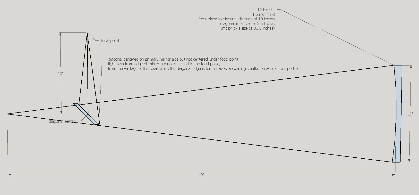
...and in detail...
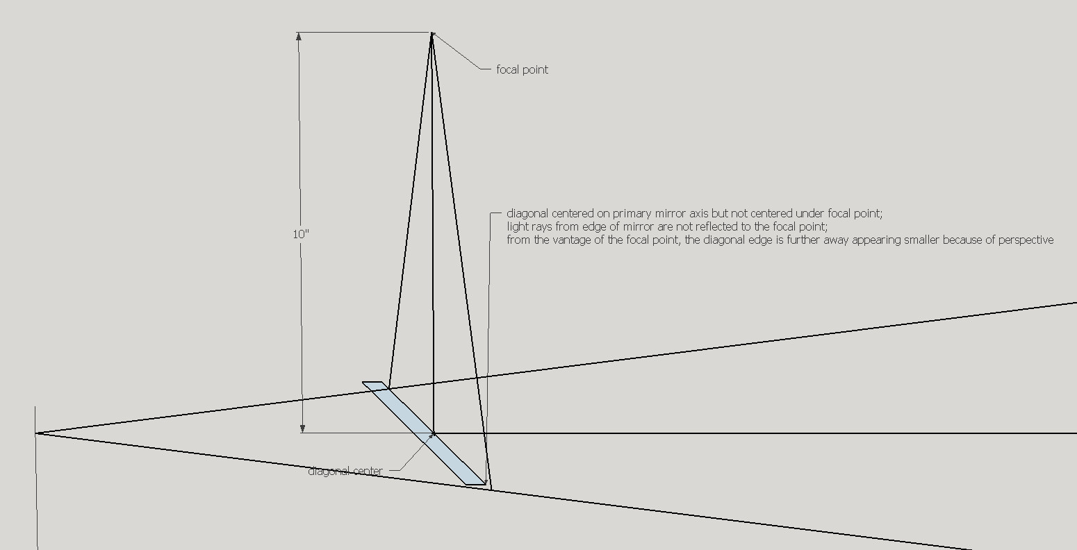
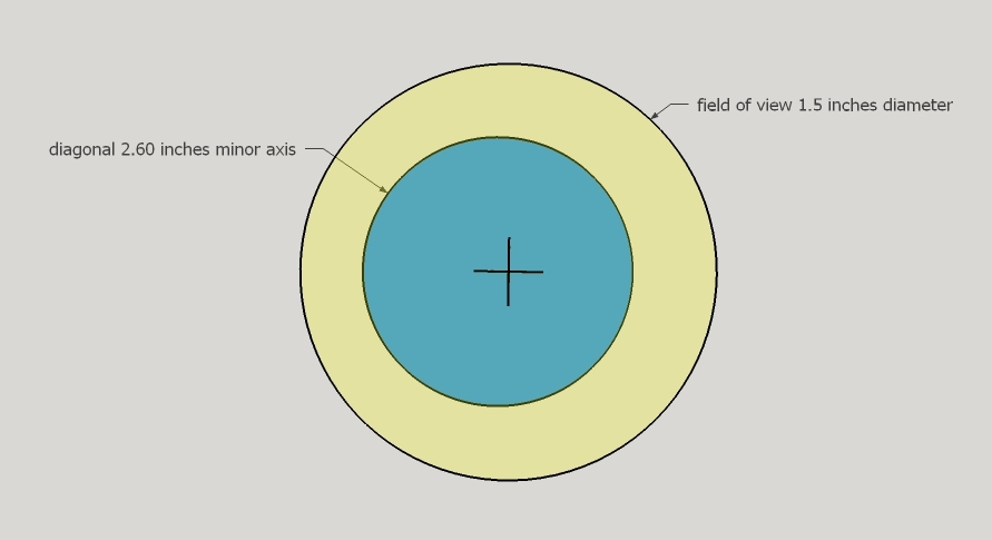
Oops, centering the diagonal on the primary mirror's axis results in the diagonal not being centered under the focal point. Projection causes the near edge of the diagonal to appear bigger because it is closer and the far edge of the diagonal to appear smaller because it is further away. The diagonal does not evenly intercept the light rays converging from the primary mirror.
Re-aligning the primary mirror slightly upward so that the converging light cone is aimed squarely at the diagonal does not work because the reflected converging beam will not be centered under the focuser, because the re-aimed mirror's axis is no longer coincident with the mechanical axis resulting in pointing errors and because the tilted incoming beam of light is vignetted by the upper end.
Our only recourse is to slide the diagonal towards the primary mirror and away from the focuser like this.
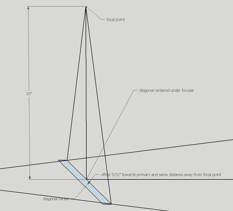
Now the diagonal intercepts the entire light cone converging to the focal point. But what about the field of view, particularly the edges of the field? Here's the layout for a 1.5 inch [3.8cm] wide field.
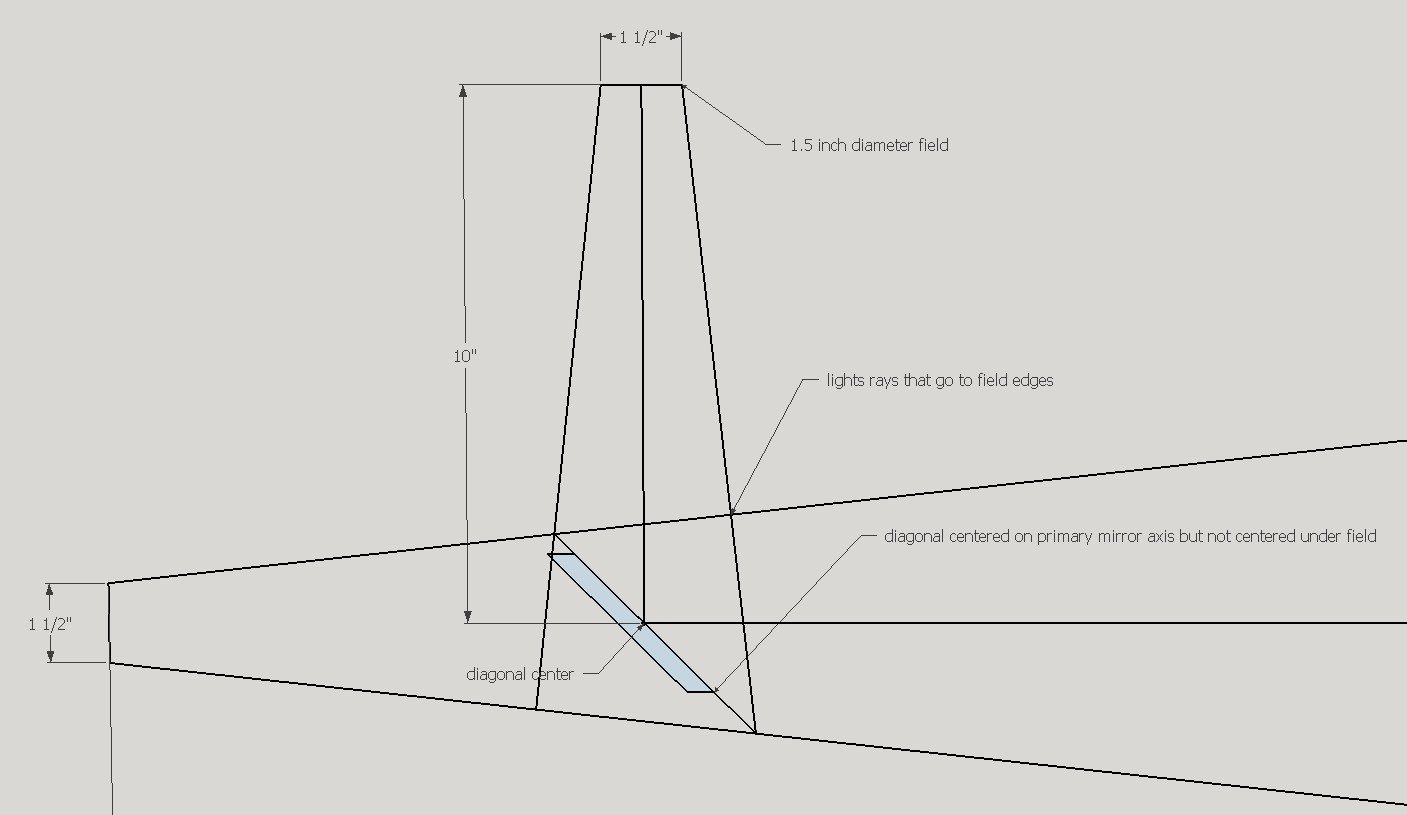
Let's add in the light cones from the left side and right side of the field. Note that just like the light cone converging to the focal point, the light cones have an angle of 14.4 degrees.
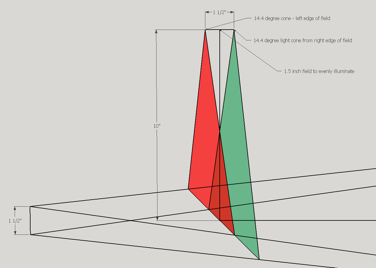
Now let's place the diagonal, offset to illuminate the focal point properly as above.
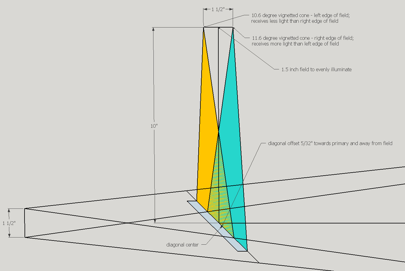
First, we see that both light cones are vignetted by the diagonal size, leaving us with illumination falloff at the edges of the field of roughly 0.4 magnitude. Secondly, we see that the right edge of the field receives more light than the left edge of the field as the left edge has a 10.6 degree cone of illumination and the right edge has a 11.6 degree cone of illumination.
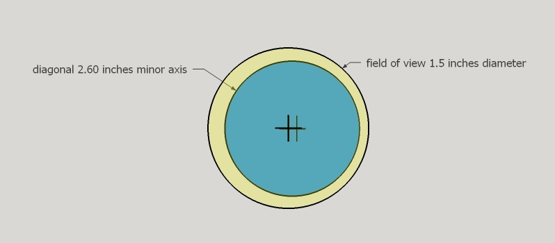
By reducing the offset by a third, the diagonal can be repositioned to balance the edge illumination reaching the left and right edges of the field, but then the primary mirror's entire converging cone of light will be slightly off-center to the left.
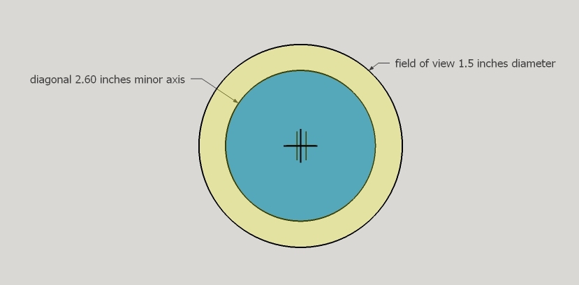
Here's my derivation of the formula to calculate offset by balancing the angles from the field of view's edges.
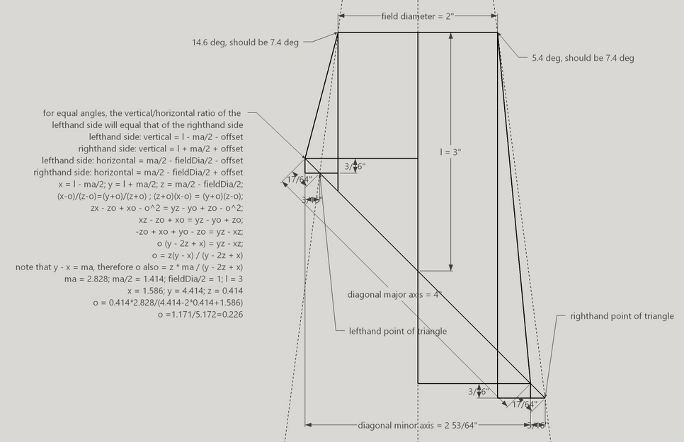
Every aspect of telescope design is a compromise that can be optimized. For example, consider aperture. More aperture means deeper (and narrower angle) viewing but at the cost of size, weight and price. Is a larger aperture scope used occasionally in dark skies a better value than a smaller scope set up in the yard?
Two unheard of optimizations are 1) a narrower upper end and 2) intrusion into the light path of the coma corrector. What do I gain by doing so?
In some cases a smaller tube diameter leads to a smaller diagonal with good light throughput and less weight. Allowing the coma corrector to intrude into the light path results in a smaller diagonal that obstructs less light than the coma corrector. The smaller tube diameter does not obstruct the light significantly. And the intrusion does not materially affect the images. Here's an optical study by Rob Brown on these kinds of intrusions. If the tube is closed with no active air movement, then allow 1/2 inch [1.2cm] for air currents to creep along the inside of the tube.
A narrower upper end means less weight, a smaller spider, perhaps a smaller diagonal and potentially a correspondingly smaller mirror box. In a fast focal ratio telescope, the diagonal is typically sized to deliver adequate (not 100%, but 70% or so) illumination at the edge of the lowest power eyepiece. Looking from the extreme off-axis point as we see in the graphic based on looking through the focuser's edge, we see that the portion of the primary mirror that is vignetted by a narrower upper end is very small, in the neighborhood of several percent or a few hundredths of a magnitude.
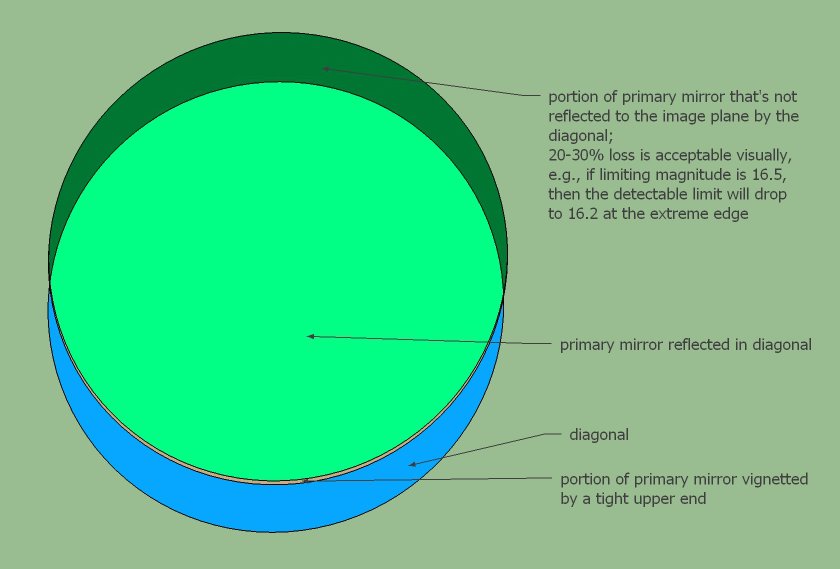
Optimizing diagonal size is all about selecting for the smallest responsible diagonal. Moving the focuser closer into the diagonal means a smaller diagonal. For fast focal ratio scopes, the minimum diagonal size is calculated by dividing the diagonal to image plane distance by the focal ratio. For example, if the diagonal to image plane distance is 12 inches and the focal ratio is f4, then the minimum sized diagonal is 12/4 = 3 inches. For very fast scopes, f3.5, f3.0, f2.5, the coma corrector can jut into the light path. So the focuser is moved outward, resulting in a larger diagonal. But let's think about what we are truly optimizing, namely, obstruction. Obstruction reduces the light going to the image plane and produces diffraction. More obstruction, more diffraction (the shape or edges of the obstruction determines the shape or style of the diffraction). The total obstruction of a minimally sized diagonal and the coma corrector slightly jutting into the light path can be less than a larger diagonal by itself. This is a worthy optimization to make, minimizing light loss and diffraction.
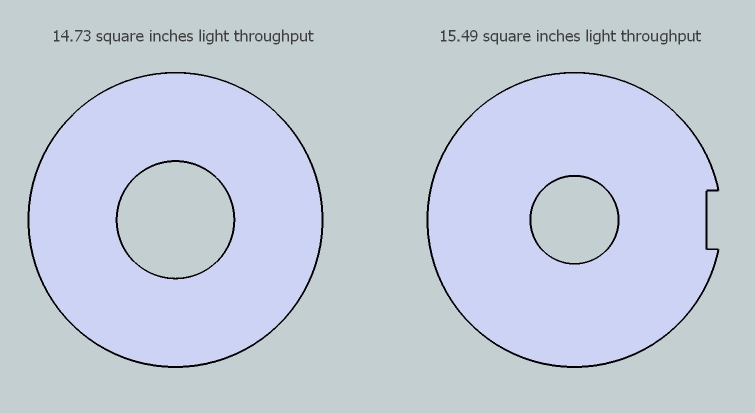
Here are two of my telescopes showing that allowing some P2 intrusion not only results in a smaller diagonal but slightly less overall obstruction.
30 inch [76cm] f2.7 comparing 6.5 to 7 inch [165 to 178mm]
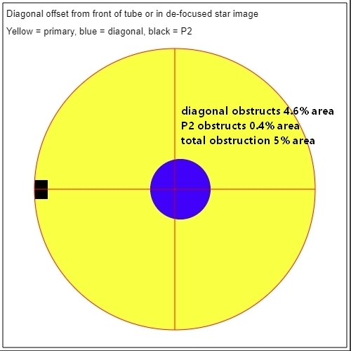
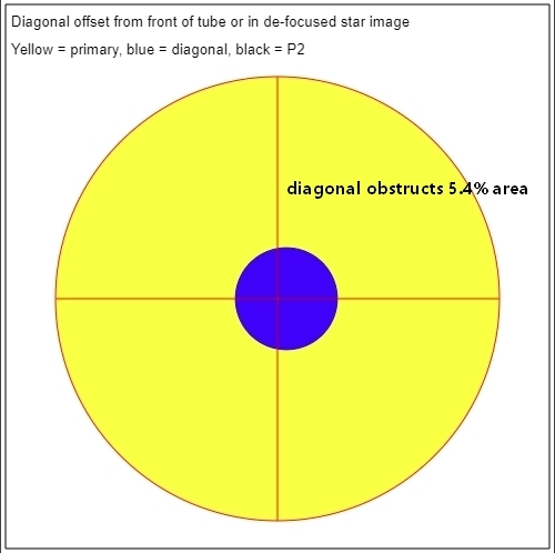
6 inch [15cm] f2.8 comparing 2.14 to 2.6 inch [54 to 66mm]
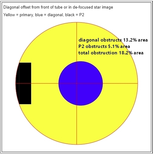
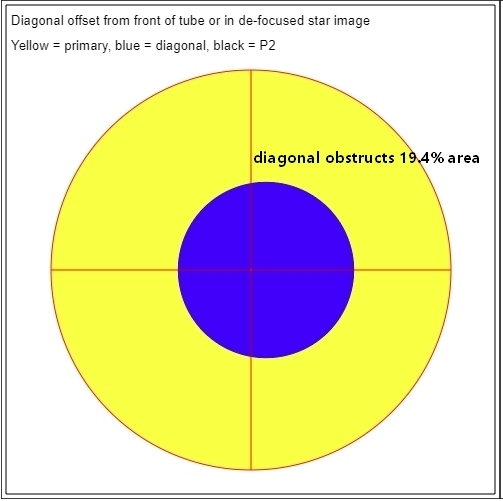
A narrower upper end and allowing some intrusion of a coma corrector into the light path are two optimizations to consider.
Stopping down by using an off-axis mask is a time honored way to beat seeing and to cut the dazzling light of the Moon and bright planets in large aperture scopes.
Stopping down is less popular today. This could be so because of drifting preferences. It is also a testament to learning how to use large Dobsonian mirrors in the dropping night time air by cooling them with fans.
The maximum diameter of an off-axis mask is set by taking the primary mirror's diameter and subtracting the diagonal's minor axis size then dividing the result by two. For example, a 16 inch with a 3.5 inch diagonal has a maximum off-axis mask diameter of (16 - 3.5) / 2 = 6.25 inches. If placed opposite any diagonal offset, the off-axis mask's diameter can be increased by the offset.
The light throughput is the inverse of the mask diameter to primary mirror diameter squared. Using the numbers from above, (off-axis mask diameter / primary mirror diameter) squared is (6.25 / 16) ^2 = 0.15 or 15% light throughput. That dims the Moon's brightness by two magnitudes.
When using an off-axis mask at lower powers, be sure to account for vignetting due to smaller sized diagonals that act to clip the off-axis aperture.
Make a black cardboard mask with a one inch off-axis hole and aim at a bright star. The Airy disk and many rings look textbook beautiful. But that costs resolution. Of course this resolution is wasted at low magnification.
What is the relationship between the off-axis mask's resolution and the telescope's magnification? What size should the off-axis mask be to resolve all that is possible at a particular magnification?
Since the eye's entrance pupil at best resolution is 1mm in size, the eyepiece's exit pupil is the factor that the primary mirror's aperture can be reduced. For example, an exit pupil of 6mm (the exit pupil is calculated by taking the eyepiece's focal length in mm and dividing by the primary mirror's focal ratio) means that the off-axis mask should be 1/6 the diameter of the primary, an exit pupil of 3mm means that the off-axis mask should be 1/3 the diameter of the primary. This leads to the conclusion that the smallest exit pupil to use with the maximally sized off-axis mask is 2-3mm.
There is also a very simple and easy to remember relationship between aperture and magnification with respect to resolution. And it is this: the telescope will resolve all that the human eye can see when the aperture in inches equals the magnification divided by 25. For example, at 100x, the off-axis mask should be at least 4 inches in diameter, 100 / 25 = 4.
For the 16 incher's off-axis mask mentioned above, the optimal magnification is 6.25 * 25 = 156x.
That's it! Now you can make those off-axis masks understanding the brightness reduction and the best fitting magnification (or what diameter to make the off-axis mask given a desired magnification).
Note: double star observing with smaller apertures can double, even quadruple the optimum magnification, up to the seeing limit of the sky, in order to better see the Airy disk and rings.
A final note: large off-axis masks on fast scopes require a coma corrector just as the full aperture view. Otherwise the star image is badly distorted by astigmatism. Selecting a different quadrant for the mask makes a difference. Tilting the eyepiece by about 5 degrees may help. For an in-depth discussion, see https://www.telescope-optics.net/tilted3.htm.
Select a spider type
| Spider Type | Diffraction Pattern | Description | Strength | Weakness | Examples |
My wire spider for the 25 inch [64cm] f2.6. How I wired my spider for my 20.5 inch [52cm] f4.8.
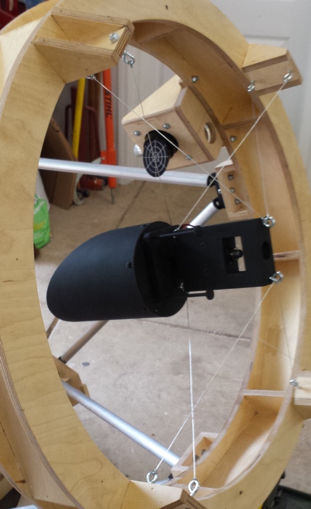
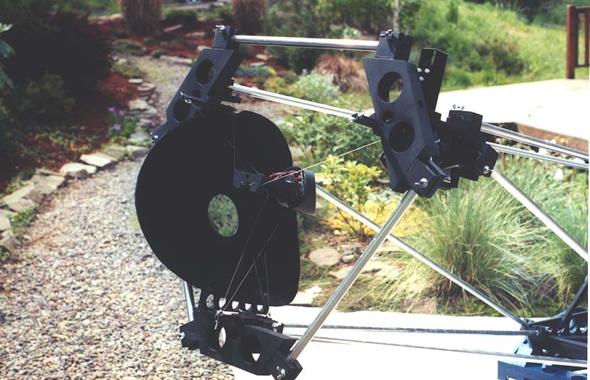
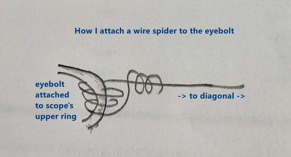
Wire spiders were popularized by Henry E. Paul in his "Telescopes for Skygazing", 1965, and in Sky and Telescope articles in the 1950's and 1960's. In the early 2000's, Jonathan Pogson, Mark Cowan, Jerry Oltion, Larry Shaper and I began investigating and using wire spiders. The reason is that we found that wire spiders give refractor like views.
Babinet's principle states that the amount of light diffracted is proportional to the area obstructed; the obstruction's shape determines the shape of the diffracted light.
The length of the diffraction spike is inversely proportional to the spider vanes thickness. For example, if the spider vanes are half as thick then the total diffracted light is cut by half and the length of the spikes is increased, causing a further reduction in the brightness of the diffraction spikes.
I use wire spiders because they are very thin and do not exhibit thermal issues that result in enhanced diffraction. It is surmised that the metal vanes cool, refracting light around them. In fact, I only see tiny narrow spikes in large apertures on the brightest stars. I find refractor like views aesthetically satisfying.
In comparison a standard 3 or 4 vane spider produces multiple bright and long spikes, and a single stalk diagonal holder creates two long, bright and thick diffraction spikes. On every single star. Annoying.
It is important to wrap your arms around the fact that wire spiders gain their strength from geometry, not from tensioning. Increasing the tension on the wires does not make the wire spider stronger. The wires are tightened only to the point of not sagging.
Every diagonal needs two support considerations:
Therefore wires need two geometries:
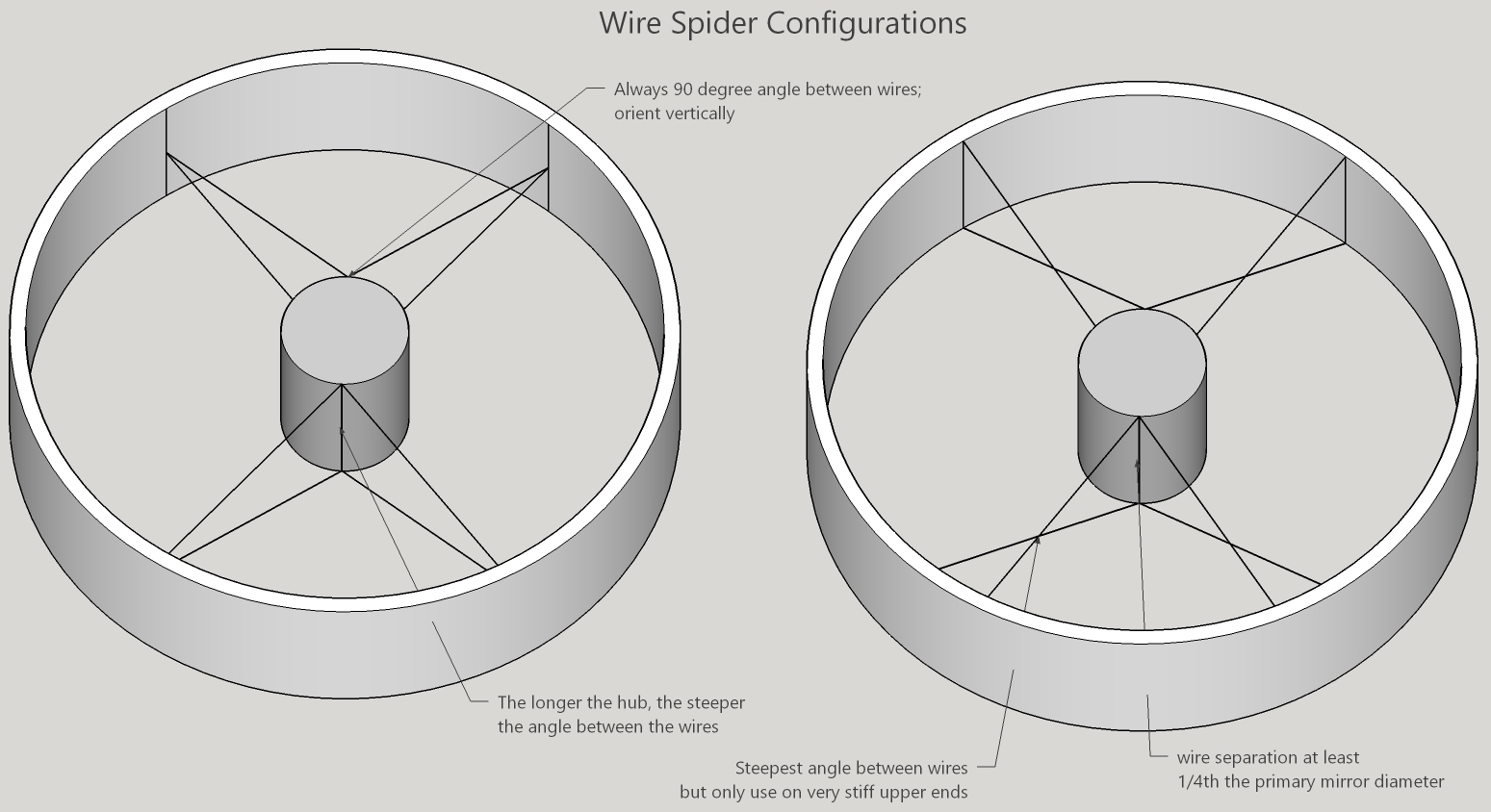
Future exploration includes a thin single stalk vane in combination with thin wires.
Since the diagonal is cantilevered, the spider can deform, misplacing the diagonal. One approach from decades ago is to add a small counterweight on a longer arm opposite the diagonal. This carries with it the downside that the diagonal can vibrate at a low frequency if energy is dumped into it.
Results:
Or select a custom value:
3
6
9
12
18
27
54
Mirror cell dimensions:
The primary mirror cell has two purposes:
These cell designs are a starting point. I like to think of the mirror cell and the mirror working in concert to deliver a quality wavefront to the focal plane. In fact I do final figuring with the mirror in its cell.
In my experience, thermal cooling issues, cooling fan induced deformations, and less than perfectly made mirror cells including poor edge support, all contribute to deform the primary mirror more than mirror cell deformation calculations suggest. Studies show that thermal issues restrict borosilicate glass to 1/10 wave; plate glass is worse unless it is very thin.
A simpler well made mirror cell outperforms a more complicated poorly made mirror cell. 1/20 wave is a reasonable criteria. The mirror stays well within the Danjon-Couder criteria of a smooth surface with total deviation a small fraction of a wave. Mirror cells weren't really a 'thing' until amateurs began making larger thinner mirrors. Though Texereau mentions more elaborate mirror cells a half century ago and the original ATM series featured Hubble's 18 point support. And floating support points go much further back all the way to Herschel.
A telescope mirror sags between support points due to gravity bending and shearing. There are three approaches to calculating the necessary number of support points so that the bending and shearing of glass is insignificant at the focal plane. They are: 1) Hubble's equal area rule, 2) structural deformation calculations, and 3) finite element analysis. To a useful approximation, all three agree.
For a 3 point support, minimum bending before refocusing occurs at the 70% radius while after refocusing minimum bending occurs at the 40% radius. See David Lewis' discussion and further references to Luc Arnold and Richard Schwartz. Texereau placed the support points just inside the edge to better position the mirror with respect to the edge supports. We can conclude that the radius can range from 40% to near 100% with but a slight degradation in the cell's ability to support the mirror.
For a 6 point support, the ring that the 6 points form is best placed at a radius of 57% according to PLOP. Six point designs are nearly as good as 9 points and have been popular from at least the 1960's. The support radius can vary from 50% to 71% without too much degradation. It is interesting that by turning a 3 point ring into 6 points, the optimal radius moves outward closer to an equal area inside and outside of the ring.
Perhaps surprisingly, a 6 pt support slightly out performs a 9 pt support and performs nearly as well as a 18 pt support. Analyzing a 16 inch mirror per PLOP, the 6 pt support's bending and shearing is 1/100 wave while an 18 pt support is 1/128th wave. That's a difference of ~ 1/500 wave! The 6 pts are arranged in a ring where the mirror's center and edge sag equally. In any event, as the mirror is tipped up on its edge, the edge support comes into play and deforms the mirror much more than 1/100th wave.
For a 9 point support, place the inner ring at the 33% radius and the outer ring at the 72% radius. If x is outer radius and y is inner radius then balance point = 2/3(cos(30)x-y) + y) = 2/3*cos(30)x + y/3 = 0.577x + y/3 = 52.6%.
For a 18 point support, place the radii at 38% and 76%. If x is outer radius and y is inner radius then balance point = 2/3(cos(15)x-y) + y) = 2/3*cos(15)x + y/3 = 0.644x + y/3 = 61.6%. Using similar math as the 9 point support design, place the bar centers at the 53.4% radius.
John Dobson used an alternative arrangement to balance the 18 points. Instead of 3 bars leading to 6 triangles leading to 18 support points, John used 3 triangles leading to 9 bars leading to 18 support points.
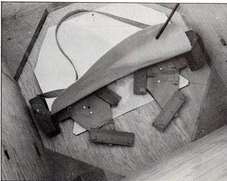
To further lessen the mirror's bending over sharp support points, spread out the deformation with miniature support triangles or circles of material sanded to fit the mirror's backside can be fitted to each support point. This can reduce deformation that appears in the star test as coarse surface roughness.
The triangles and bars can float or an astatic design can be adopted where there are three fixed points (which can be floating triangles themselves) and an equal number of astatic points.
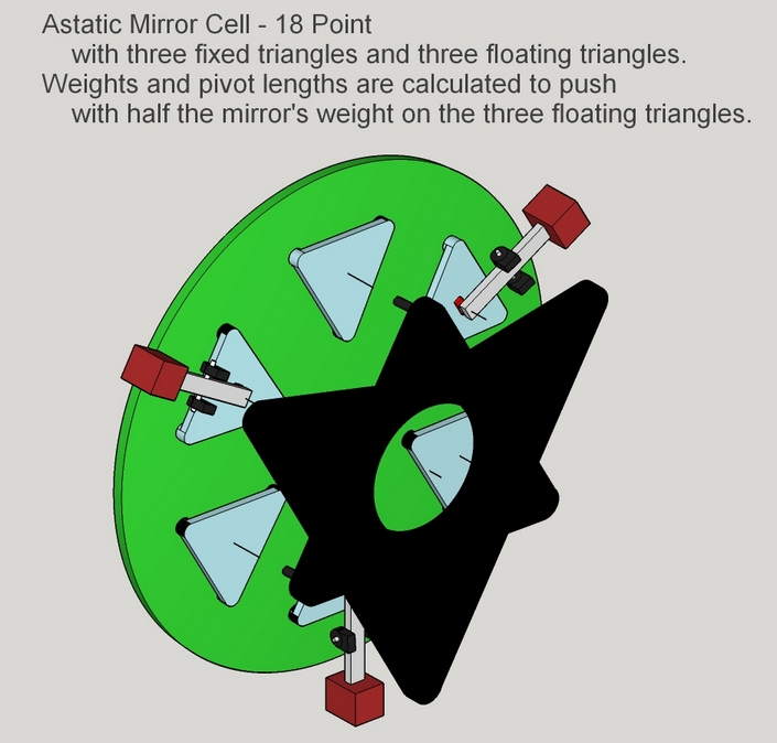
Important is the quality of construction and the balance of the pieces. A poorly made 18 pt is far worse than a well made 6 pt cell. Considering other factors helps us rationally judge how much bending and shearing is acceptable in a mirror cell. Focusing can easily introduce an additional 1/4th wave error; less than perfect collimation deforms the wavefront by a considerable degree. Additionally the diagonal's and primary mirror's quality should be soberly assessed. Then there's seeing to consider.
If using flotation cells, then the pivoting should be as close to the mirror's back side as possible. Another reason to keep the stack of bars and triangles to a minimum. This implies that the support bars and triangles be as thin as possible.
My definitive test is to move the scope from zenith to horizon: the brighter high magnification star images should be perfectly tiny round discs of light. Even with bloated poor seeing near the horizon, mirror cell issues are pretty easily seen.
Edge supports are analyzed in R.N.Wilson's Reflecting Telescope Optics, Volume II, pages 264-271. The author summaries modeling and results of various edge support designs on 1-4 meter mirrors. He finds that:
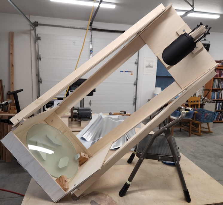
The edge support points or sling should be at the mirror's center of gravity. Use the 'center of gravity' calculation that I include in the 'Telescope Designer' section. I've found for large thin mirrors that even a small displacement of 1/8 inch [3mm] away from the center of gravity can cause noticeable deformation in the high power star test.
Check out the mirror sling on my 30 inch diameter, 5/8 inch thick meniscus mirror telescope and on my 16 inch diameter 3/8 inch thick meniscus mirror telescope along with Howard Banich's 30 inch diameter 5/8 inch thick meniscus mirror. Here's John Dobson's sling and mirror mount for his thin 24 inch that won an optical price at the highly competitive RTMC. Note the unusual way he balanced the 18 point back support points.
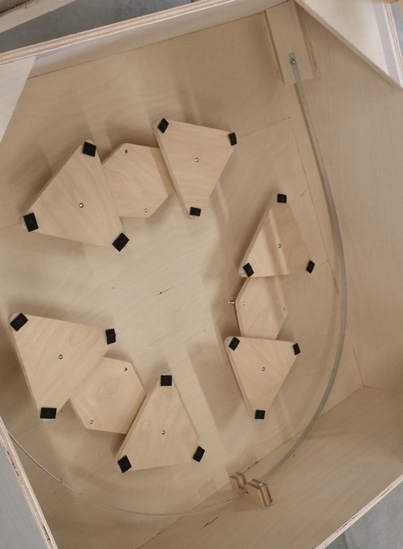
Cable slings must be applied carefully: the cable can twist lifting the edge or the attachment point might be too close to the mirror. Worst of all is a cable that stretches in the slightest - often the case with wire or chains since mirrors are usually heavy.
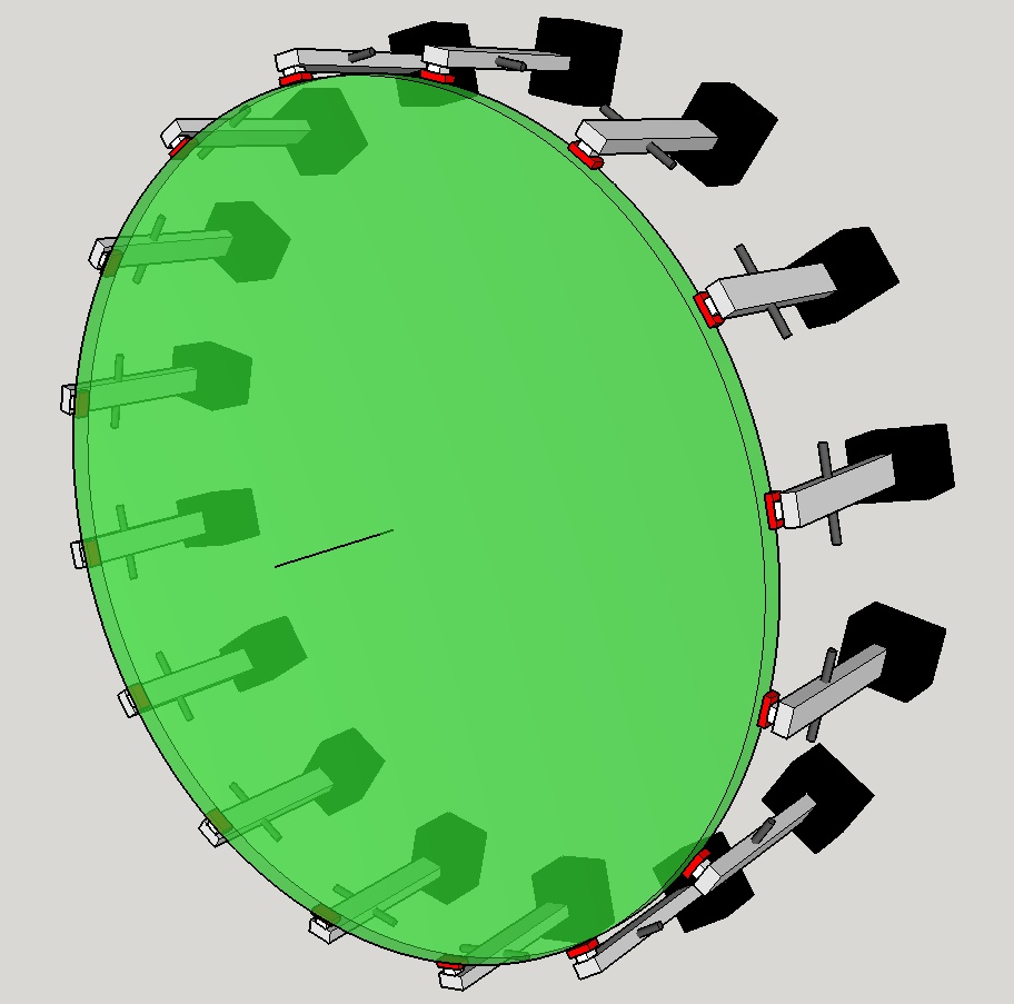
Typically the mirror's defects dominate the mirror cell, meaning that the mirror cell adds very little error to the optical system. For example, consider a mirror of 1/6 wavefront peak-valley error that is otherwise smooth. The 1/6 peak-valley wavefront is about 90 nm peak-valley wavefront error in green light. That is 45 nm peak-valley on the mirror's surface. Even a crude mirror cell of say 35 nm peak-valley error (10 nm RMS) does not materially degrade the optical performance. Errors are added by root mean square, so a mirror of 45 nm peak-valley added to a mirror cell error of 35 nm peak-valley results in a total error of nearly 57 nm peak-valley or 1/4.6 wavefront. This is a degradation of only 1/20 wavefront from the mirror's 1/6 wavefront!
We need to ventilate the mirror to:
A warm telescope set up in the colder night air undergoes cooling. If the primary mirror has a thermal coefficient of expansion, for example, borosilicate (Pyrex) glass and plate glass (quartz does not), then the mirror will deform as it cools. In fact, as the night time temperature drops until the early morning hours, the mirror undergoes continuous cooling. Additionally, the glass warms the air around it, causing deformed views like looking down at a swimming pool.
The mirror's face is exposed to the cold dark sky as the telescope is aimed at astronomical objects. The mirror's face contracts and deepens, becoming overcorrected. In addition, the edge shrinks back as it cools, creating more overcorrection.
So we cool our mirrors to restore the curve of the glass. But it is not just the mirror that needs cooling. The warm glass heats the air that clings to the front of the glass. We call this air the boundary layer. This air needs to be scrubbed away.
Consequently we may blow air on the mirror's back and on the mirror's face.
Dealing with the mirror's face, Alan Adler discovered that a fan blowing air across the mirror's face with an escape hole in the tube on the other side of the fan effectively clears out the boundary layer. The demonstration is impressive. As soon as the fan is turned on, the high power planetary image stabilizes. Turn off the fan and the image disintegrates. Chuck Dethloff and others demonstrated that hanging a centrally located fan on thin wires directly above the mirror's face works. Ed Allen developed a system where the air blowing on the mirror's back side is directed around the mirror's edge then channeled to scrub the mirror's face. And Mike Lockwood has shown that four corner fans blowing obliquely on the mirror's face is effective too. He's also found that turbulence is better than laminar flow in removing heat from the mirror.
Owners of larger mirrors need to be careful about where the fan blows. It is easy for three fans arranged in a triangle to preferentially cool three areas of the mirror's back side, creating trefoil astigmatism.
Large ultra thin meniscus mirrors can change their parabolic shape due to the glass acting as a bi-metalic strip where the front cools faster than the back.
Large mirror cooling strategies that worked for me:
24 inch F5.5 x 1.5 inches thick borosilicate: in a deep enclosed mirror box. Performed well after a cooldown period of 30 minutes. No fan.
20.5 inch F4.8 x 2 inches thick borosilicate: very open framework without a fan. Often used at 1000x, one night at nearly 6000x.
16.25 inch F2.9 x 3/8 inch thick meniscus shaped plate glass: enclosed tube assembly: the mirror is ready to go as soon as I remove the dust covers and performs well all night with no issues. No fan.
30 inch F2.7 x 5/8 inches thick meniscus shaped plate glass: enclosed tube assembly, a small fan blowing at the center of the mirror's backside and four small corner fans blowing air across the mirror's face.
References:
David Lewis' PLOP, the mirror cell finite element analysis software.
Robert Houdart's mirror cooling discussion and software.
Mike Lockwood's "A modern Guide to Mirror Support".
Mike Lockwood's "Thermals and Telescope Optics", Winter Star Party, 2024.
Bryan Greer's fan discussion
Ed Allen's Complete Ventilation System (C.V.S.) for Amateur Telescopes, 2020.
Alan Adler's thermal management system.
Chuck Dethloff's face-on fan.
Allyn Thompson's Making Your Own Telescope and
Jean Texereau's How to Make A Telescope. These books discuss thermal experiments done mid-century.
A focuser can focus at the eyepiece, slide the eyepiece and diagonal, adjust the tube's length or move the primary mirror to and fro.
Baffling on my 20.5 inch [52cm] F4.9 TriDob. Pictured is the diagonal baffle to the right of the diagonal and to the left, the focuser pre-baffle in front of the focuser's mounting board. The baffles are designed to block all direct light that could find its way into the focal plane of the eyepiece. The focuser baffle works to reduce the diagonal baffle's size and further constrain stray light entering the focal plane.
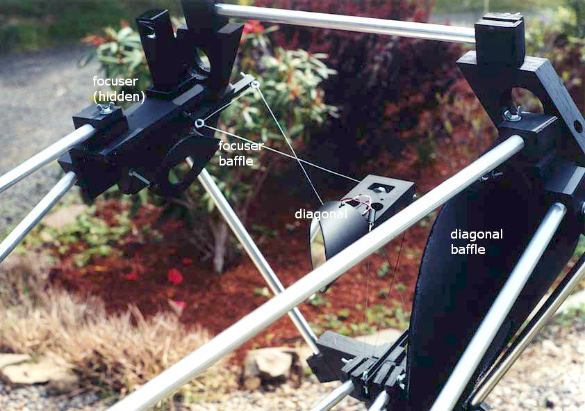
| Distance between the diagonal and the focuser baffle = | |
| Adjust scaling |
Results:
| Adjust scaling |
| Results: |
We want the 'good' light to reach our eye, the 'rogue' light to be blocked. Some rogue light we simply cannot block because it comes from the upper atmosphere exactly between the object and our telescope. This includes sky glow and reflected light pollution. Other rogue light strays into our eyes. This we can block with a hood over our head or by cupping the eyepiece with our hands. Remaining rogue light can sneak past the diagonal into the eyepiece and sneak past from behind the primary mirror, bouncing off the diagonal to fog the eyepiece.
The rogue light sneaking past the diagonal can be blocked with a baffle. This baffle is called the projected focuser baffle or diagonal baffle. And rogue light sneaking past from behind the primary mirror can be blocked by baffles that surround the primary mirror. This baffle is called the primary mirror baffle. The baffle designer calculates the minimum size for these baffles based on geometric light ray traces. An additional baffle, not shown and not calculated, can be placed just below the focuser to tighten up the projected focuser or diagonal baffle.
Using an idea by Larry Shaper in Amateur Astronomy magazine, Issue #91, Summer 2016, page 52-53, the edges of the baffle can be tilted to direct light away from the focuser's tube bottom aperture. Larry concludes that the flattest black paint always looks gray while a baffle painted in gloss black with tilted sides looks truly black. You can see that the tilt angles light past the focuser tube and is long enough that light reflected at a narrow angle face on is also directed away from the focuser tube. Since the optical tube assembly can be open, I tilt the projected focuser baffle on both sides.
Design the baffle by starting with projecting the light from the focal plane to the bottom of the focuser's tube. This cone of light needs to be blocked to prevent fogging of the focal plane. This is colored lime green. Next, set the angle of the baffle by dividing the angle between the lines: the vertical line across the tube opening and the line from the tube front bottom to the inside bottom edge of the focuser tube. This is colored light green. Finally, determine the edge of the angled baffle segment by finding the point where light is blocked from the bottom of the focuser tube. This is colored dark green.
| Adjust scaling |
| Results: |
By increasing the diagonal's angle, we can aim move the focuser a little closer to the primary mirror, lessening the eyepiece's height above the ground.
Why a folded reflector (popular name, 'low rider')? It's all about convenience: the eyepiece height above ground is shortened. This can make the difference between ladder and no ladder or between high up a ladder and stepping up onto a stool.
Baffling is an issue. Needed are a focuser baffle just below the focuser to block the extremely wide angled light and an additional baffle on the farside of the diagonal or on the farside of the tube.
An early example of a folded (or low rider) reflector is Ed Danilovicz's 12 inch, featured in Sky and Telescope magazine, April 1976 pg 278. A more recent astonishingly impressive example is Mike Clement's 70 inch, featured in a variety of online articles and forums. Here is Dan Gray's 28 inch showing less onerous though still significant baffling around the secondary.

Surprisingly, the optimal bending angle that minimizes the secondary's major axis is not the standard 90 degrees, but instead is closer to 60-70 degrees. The major axis matters because that is the size of glass that the secondary is cut from, whether elliptical or spherical. Here is a study that additionally shows that the secondary can be made spherical when the bending angle exceeds 30 degrees.
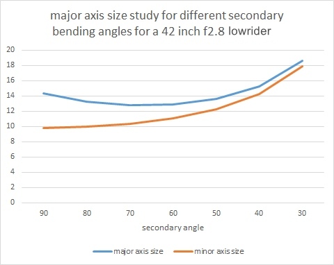
| Secondary reflection angle (deg) = | |
| Eyepiece divergence (deg) = | |
| Optical axis downward tilt (deg) = | |
| IPD (InterPupillary Distance) (mm) = | |
| Adjust scaling |
| Sideview results: | |
| Frontview results: |
The gray shape represents an adult human's face, neck and shoulders.
The secondary is calculated for minimum size to illuminate the center of the field of view. The tertiary is calculated for full illumination of the field, which may be excessive.
A bent tertiary (adding eyepiece divergence) can reduce secondary to tertiary distance, permit a smaller secondary and reduce central obstruction. The eyepieces are consequently tilted toward each other and optionally slid off-center. Here are images of a proposed 30 inch F2.7 bent design. You can inspect this design by switching to the Export/Import designer then selecting the proposed 30 inch design.
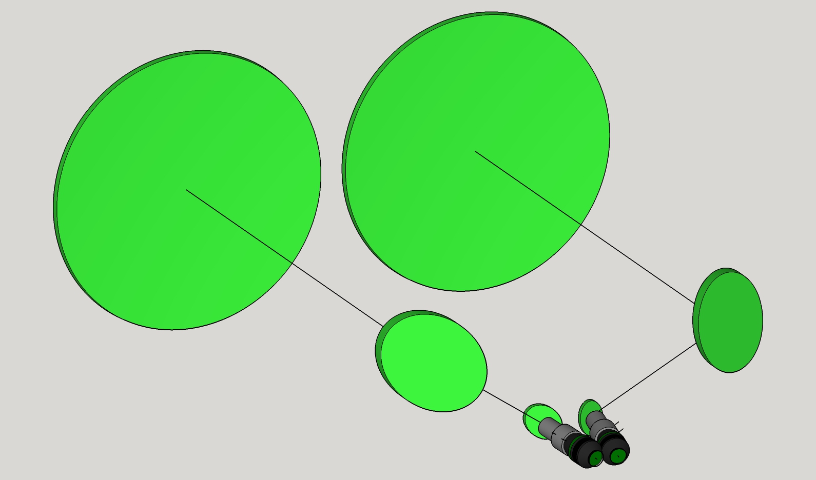
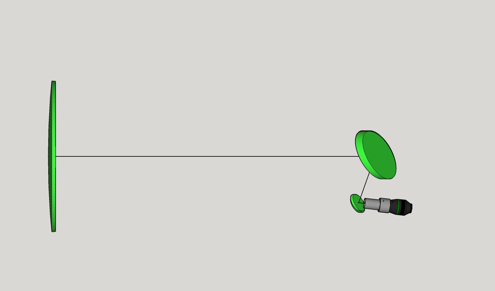
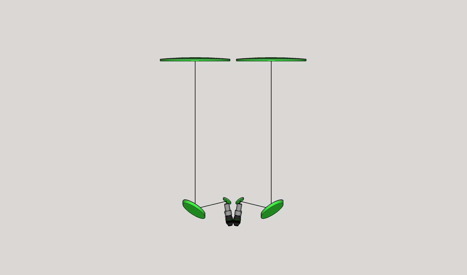
Here's another illustration of a proposed 8 inch F3.1 binoscope with divergent eyepieces.
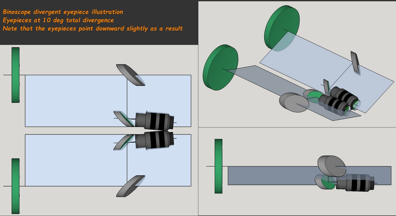
The primary mirror, secondary and tertiary mirrors form a plane. The eyepice can change angle as long as it stays in this plane. What's not ok, what causes image rotation, is when the eyepiece rotates up and out of this plane. For example, trying to use the tertiary mirror to create a more comfortable eyepiece angle. For more, see this Cloudy Nights discussion with paper drawings by Clive Milne.
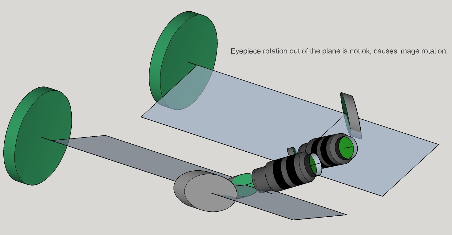
Diverging eyepieces can also narrow the IPD; even become the IPD adjustment mechanism.

The idea originates with Clive Milne, who writes, "To see what this looks like, just hold a pair of [low power wide angle eyepieces] up to your eyes and look at a blank wall. Concentrate on one eye; orient the eyepiece such that its field stop is visible in the direction over the bridge of your nose. Now orient the opposite eyepiece such that it's field stop edge is displaced about 1/10th the native field of view. That's what 5° tilt per side looks like. Go further and see if you like 10° per side. I suspect it is subjective and somewhat personal, but the field really seems to open up for me when you do that. When the eyepieces are parallel (with overlapping field stops) at no stage does it feel natural. Even though I can get my eyes over the exit pupils I'm very conscious of the fact that they don't really fit my face all that well in parallel mode."
When the eyepieces diverge and the tube assemblies are aligned parallel pointing to the same spot in the sky, then the axes of the eyepieces must be offset from each primary mirror's optical axis. If the eyepieces are coincident with the primary mirror axes and the eyepieces diverge then the two primary mirrors must point to different spots in the sky for the images to align in our eyes. For example, if each eyepiece diverges by 5 degrees and the binoscope with eyepieces magnifies 60x, then each primary mirror must diverge by 5 arc-minutes; if magnification is 120x then each primary mirror must be re-merged at 2.5 arc-minute offsets. So, changing eyepiece sets requires re-merging.
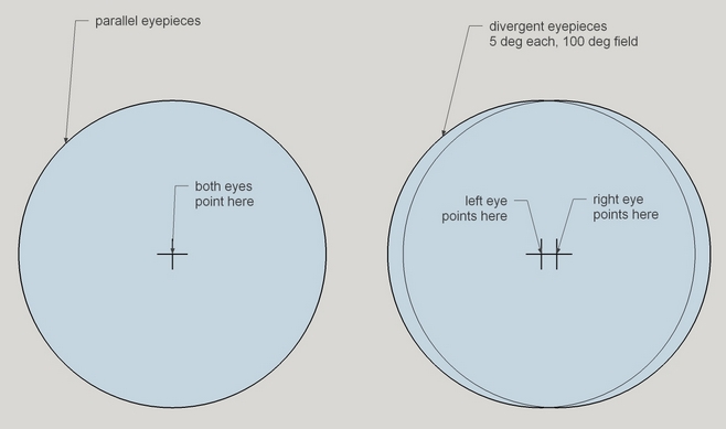
And diverging eyepieces increase the overall field of view, albeit decreasing the field that both eyes see. It remains to be seen how this affects observing. Perhaps the slightly more rectangular view facilitates detection.
To get a clear understanding of binoscope reflections, I used CAD and cheap mirrors set up in my shop.
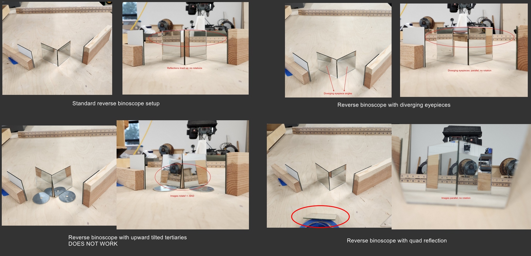
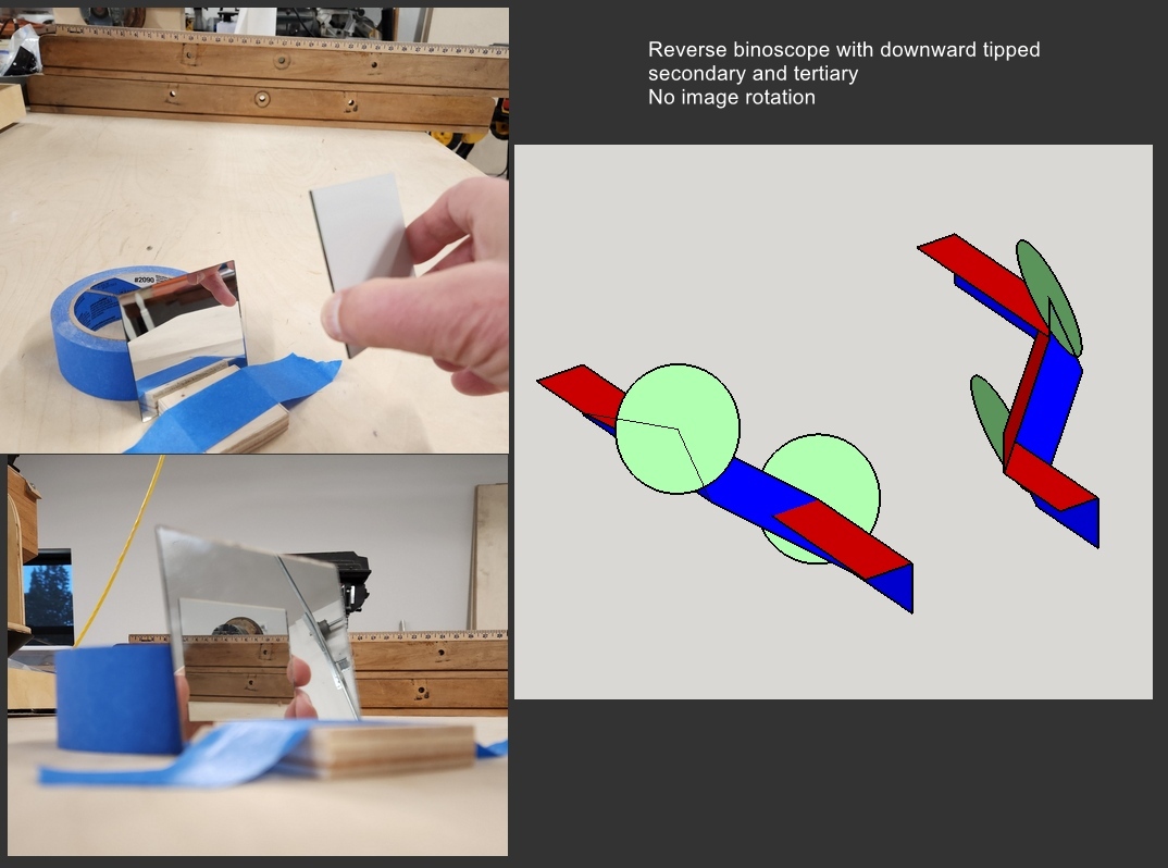
For more on this, see this Cloudy Nights discussion.
The topic of binocular summation, or what is an equivalent monoscope aperture compared to a binoscope, is popular. The views in the monoscope and binoscope are not comparable, unless the monoscope is equipped with a binoviewer that splits the light between the two eyes. With this in mind along with the observation that results vary from observer to observer and from binoscope to binoscope, I find that faint stars are enhanced by anywhere from 20% to 40% and faint extended nebulae by 40% to 100%. For example, a 10 inch binoscope is equal to a 12 inch to 14 inch for faintest stars and equal to a 14 inch to 20 inch for nebulosity. The binocular summation factor is thought to be a combination of probability summation, an increase in the signal to noise ratio, and neural summation. For a cogent discussion, see https://arieotte-binoscopes.nl/Binocular Summation Factor.pdf
Let's compare a monoscope with a binoviewer to a binoscope, say a 10 inch [25cm] monoscope. With the binoviewer each eye gets half of the 10 inch aperture's light or the equivalent light from a 7 inch [18cm] binoscope. The comparison then is that a binoscope is equivalent to a monoscope of 40% greater aperture equipped with a binoviewer.
Notwithstanding binocular summation, I find the greatest advantage of a binoscope to be a milky smooth perspective to extended objects. Returning to monocular viewing (as simple as closing one eye), I see extensive and bothersome mottling and scintillation that gradually recedes over an hour or two.
At a 2018 shootout between 10 inch [25cm] telescopes of varying focal ratio, an 8 inch [20cm] binoscope and my 25 inch [64cm] f2.6, with four very experienced amateurs, the 8 inch binoscope on the Veil Nebula performed closer to the 25 inch, clearly outpacing the 10 inch scopes by a considerable margin.
Here is my report of our 'shootout' between a 28 inch [71cm] monoscope and a 22 inch [56cm] binoscope. In a test conducted October 24-25, 2003 at the Shingletown air strip three of us experienced observers were able to compare the 22 inch binocular to Dan Gray's innovative 28 inch string telescope (an aperture ratio of 1.27). Benchmark objects included the NGC 281 edge-on galaxy, the Andromeda galaxy, Einstein's Cross, the Perseus double cluster and the Great Orion nebula. The consensus:
We compared an 8 inch binoscope and a 30 inch telescope in 2025. The views are so wildly different that the three of us concentrated on the aesthetic pleasure, delight and novelty of the views. Views of wide scale nebulosity and composition of objects was surprisingly novel and serious in the 8 inch binoscope. Of course, views in the 30 inch were novel and surprising too. The 8 inch binoscope couldn't compete on stars and colors of stars nor on the typical planetary nebula nor on galaxies other than the show galaxies. Overall, I found the 8 inch binocular scope as enjoyable as the 30 inch.
From his video. "Comparing binocular views to telescope views is missing the point because looking through binoculars is just an entirely different experience. Big telescopes definitely have their advantages. I'm not saying big big [8 inch] binoculars completely replace everything a 14 inch or 18 inch Dobsonian can do. But when it is time to express the overall binocular experience, different things emerge beyond simple brightness and detail. The big thing is it's about a thousand times more comfortable to look through both eyes than one. Being comfortable means you can focus on detail better, which means you need less magnification, which means brighter wider views where you're taking in so much more. The scenes I'm seeing are so different from what my friends are taking in through their telescopes. Even familar objects feel different and brand new. If you told me that I had to choose between my 8 inch binoscope or a big telescope, how big would the telescope need to be? I really think it would have to be at least a 20, maybe a 25."
Early light with his 50mm 'Heart' and 8 inch 'Bloom' binoscopes. "I started around Sadr in Cygnus and it was awash in not only stars of every color but doubles I’d never seen, open clusters I’d never seen, and strong background nebulosity. I moved over to Deneb to see the North American Nebula, and it was huge! No longer does it fit in the view, let alone with the Pelican. Much more surface detail can be seen, and it's a totally different experience. I moved to the Cygnus Loop (the Veil). All four veils easily visible, southeastern knot visible, hints of southern blowout region visible. I didn’t spend too long here and only looked at 28x but there’s a wealth of new detail to see even at this magnification. Scutum was remarkable, with all Barnard dark nebulae standing out in stark contrast to the star clouds behind. All stars in M11 easily resolved at 28x. Eventually, I could move down to M24 and it was simultaneously familiar and not. The LDN nebulae framed its shape in a way I didn’t remember at all. The long, lacy arcs of stars stood in dramatic contrast, so beautiful.This is the first time I zoomed in with the 17.5 Morpheus because M24 is so immersive when it’s several fields wide.
"M24 was incredibly beautiful but I expected that. What I didn’t expect was how bright the Lagoon glowed with NPB filters at 28x. The heart of summer! The LDN were visible as were the large “wings” that point toward the Trifid. This means you’re seeing not just the bright core but the full extent of the red hydrogen area you see in photographs. The Trifid showed structure and detail. You could clearly see the “flower petals”, delineated by the radiating dark lanes. I didn't crank up the magnification on this but will be comparing the view this summer to my memory of it in Akarsh Simha’s 28”, a tremendous view.
"As I travelled further south, I came to the most enchanting view of the night, the teapot steam, the Great Sagittarius Star Cloud. Even at 28x, it spanned several 2.5 degree fields. Words fail me, so I'll point out Barnard 86 and the dark region to the south, LDN 1795. LDN 1795 is a large dark cloud south of B86 (the Ink Spot) and the journey between the two is an astonishing fabric of light and dark. Keep in mind you’re seeing a window to the galactic core through dust clouds and you get a sense of just how far away we are in the outskirts of our galaxy. One of the greatest pleasures of studying the sky is not just memorizing the two dimensional map of our cosmos, but also the three-dimensional map of the Milky Way, so that when you step outside under a dark sky, you see a three-dimensional scene above you. Studying these dark nebulae around the galactic core, getting to know them is such an exquisite part of that journey. It’s just achingly beautiful and there’s just so much to see.
"The IFN, Integrated Flux Nebulae, are patches of the background sky that brighten up because there is interstellar material floating around in the galaxy. This is the supernova material that eventually becomes new stars and grubby little humans, so looking at IFN is really being able to see a whole new stage in stellar evolution that amateur astronomers have ignored until Mel Bartels started seeking them out in his fast scopes. To be clear, we’re talking about seeing something in real time that imagers have to spend hundreds of hours collecting data to pick up. He gave us a talk on Friday night via Zoom where he encouraged people to seek these out in any instrument they have, just get the biggest exit pupil possible. Of course Bloom and Heart have two exit pupils so they’re at a huge advantage. I sought out a couple by request. First, in Heart we looked at the huge IFN wall that stretches from M31 all the way down to M33. Then we spent some time looking at M13, which is surrounded by a bunch of IFN. This was a super-cool composition where we could see much of the detail in Mel’s sketch of the area [done with a 30 inch].
Later at the Shingletown (California) Star Party, Randy Muller (responding to a question from a TAC-SAC listserv member, "What was your favorite [view] at SSP this year?") wrote, "The Lagoon Nebula, (M8) (in OIII) at around 100x through Bruce Sayre's 22" binocular. I visited Bruce near the end of the evening (actually I kept him up longer than he wanted to be up, but he graciously allowed me to look through his scope), so there was no line, and I was able to adjust precisely the inter-ocular distance and focus of each OTA."
"Never have I viewed such bright and overwhelming detail in this object. My brain interpreted the stars as being in the foreground, bright billows and wisps of nebulosity being in the middle-ground and the fainter parts of the nebula as being in the background."
"The wide-angle eyepieces, plus the illusion of depth made me feel like I was inside the nebula. As I looked, the whole thing had an almost windswept feel as if I was standing on a hill with fog billowing and blowing around me. But the image was still, so that gave it a peaceful, calm and serene tone, rather than stormy and violent."
"The color was that unearthly fluorescent blue-green typical of all the bright emission nebulae, but instead of being present only in the brightest central area, it was suffused throughout the whole nebula, with varying intensity, giving rise to a sense of varying density and thickness."
"It was an incredible view that I will never forget."
I don't have the energy (or the time) to give a full account of the first light with my [20 inch] binocular telescope, but here are a few impressions. Firstly, they worked with only a few minor repairs and tweaks, and that was a pleasant surprise considering that I took delivery of the optics 2 hours before sunset. It would be fair to say that setting the things up proved to be a little 'quirky', but that was to be expected I suppose. As they stand, the design is entirely valid for a permanent set up, and the minor modifications I have planned should ease the pain of using them on a whimsical basis. Currently, set up is a 'non-trivial' undertaking, but the issues have relatively simple solutions and all will be addressed in due course.
Some of the positives include the off-set wire spiders, which amazed everyone who tested their stability. And of course the OTA alignment joystick, which streamlined the operation by two orders of magnitude. People who had never used a telescope before found no difficulty in observing with this instrument, and no one reported any eyestrain over the two nights. What can I say other than 'it works'. The views through the instrument are hard to describe. However, to give you an idea of the compelling nature of observing with giant binoculars, consider that the first night with them, they were effectively as good as an un-baffled instrument. Every moment was so precious that we elected not to trade eyepiece time for that required to baffle the instrument properly. I don't think I have ever heard so many 'Ohhhhhhh myyyyy Goddddds' uttered in a single night. Except of course for the second night when the baffling was greatly improved. I also had the opportunity to compare a few objects using a nearby 25" Obsession. There is no denying that the views through it were quite stunning, and one could argue the merits of one instrument over the other based on limiting magnitude or faint detail perception, but that just misses the point completely. The incredible sense of total immersion in the reality of the experience is what binoculars are all about. The one positive impression that the 25" Obsession left me with was that I simply must build an even bigger pair of bino's :)
There is a negative side to observing with a giant binocular telescope though, and that is that the comfort level afforded by using both eyes means that people tend to 'hog' the eyepiece. I regularly had to suggest 'sorry, your time is up, let someone else have a look'.
As daylight now floods my eyes, I still vividly recall the visual spectacle of those first two nights. It was like seeing all my old favorite objects again for the first time. The LMC truly defies description, field, after field, after field, of ghostly fluorescent gas studded with innumerable glittering diamonds. The stars of Omega Centauri are so impossibly bright that the subtle contrasting hues of the stars themselves are clearly visible. Nameless planetary nebulae transformed into powder blue cotton balls in the sky. I also found myself appreciating double stars, star clusters and dark nebulae, classes of objects that previously never really managed to capture my interest. I found it hard not to be seduced by the shear beauty of them, they are truly transformed with the aid of binocular vision. And of course Eta Carina... I lack the words and the skill with them to even hint at the staggering beauty of this nebula. You will have to come down and see it for yourself. Finally I must give thanks to a few people in direct proportion to the assistance they gave me. Jos, thanks SO much for trusting me with your workshop. Onya mate! ;) Horst, pitching in made the difference. Christine, your patience with me made this possible. And lastly Mark Suchting, not just for his help with the mechanical aspects of the telescope, but also for the first class optical work on the primary mirrors. For the record... these primaries show no visible defects in the diffraction pattern when viewed on the test bench!!!!! I think that counts as a 1 on the Bratislav quality scale? My views on astronomy will never be the same.
On several nights over the last couple of years, I have taken my 17.5″ Dobsonian and my 13.1″ binoculars to a dark sky site. On the night of one memorable test session the seeing was very steady (unusual in Colorado) with much detail visible on Jupiter. All these optics are extremely good, with superior pedigrees and nearly perfect performance under careful testing. I tried both instruments on several targets, of various types. I made nearly all comparisons using approximately the same magnification through both (about 150x for most cases). The exit pupil was different in each instrument, of course, but fairly small so as to reduce effects due to the outer edge of the lens of my eye and make sure my 51 year-old eyes were accepting all the light. The effective light gathering of each instrument is about the same including the additional loss from the third reflection in the binoculars.
On M13, both views were spectacular, with stars resolved to the core. My notes indicate more detail in the 17″ but the detail is more obvious in the binocs. The Veil Nebula was obvious in the 17″ and even MORE obvious in the binocs, with exquisite fine detailed knots and tendrils in both. Careful comparison indicated more detail visible in the 17″, but the detail was more “true” in the binocs. My notes here indicate that the effect in the binoculars was similar to the effect that many experienced deep sky observers are familiar with which occurs when you move the telescope slightly and faint nebulosity jumps out at you; the brain tunes in to motion. Apparently the brain tunes into binocular vision in a similar fashion. Jupiter showed much banding, swirls and fine detail in the 17″. The effect in the binocs was DUMBFOUNDING! It looked as if the seeing had just been locked down to perfect! It seemed as if as much or more detail was visible in the binoculars and it was OBVIOUS! Perhaps some of this was the standard effect of smaller aperture on seeing effects. I noticed that when one eye was seeing a momentary blur, the other was seeing a clean view. Subjectively, the effect was astounding. I strongly suspect that an experienced planetary observer would be able to painstakingly extract more detail through the 17″ with many tens of minutes at the eyepiece. But, through the binoculars such information was immediate, intuitive and unquestionable. In the 17″ the dust lanes of M31 were easy. In the binoculars the dust lanes jumped out of the eyepiece and slapped me in the face!
Overall Impressions
My overall impressions were that the brightness in both instruments was about equal. Faint object detection was easier in the binocs and detail was more obvious in them as well. Discriminating appraisal indicated more actual detail in the 17″. The planetary image in the binoculars was equal to the 17″ general, but the comparison is difficult to make because the differences were qualitative. There is something profoundly satisfying and comfortable about the views through the binoculars. This is something which must be experienced to be appreciated. The effects I noticed have been described by other binocular users. Lee Cain wrote an article in the December, 1986 issue of Sky and Telescope (pg. 662) which addressed this issue, in part. My experiments seem to support his comments there. I suggest you try to get a look through large binoculars some time, so you’ll know what we are talking about.
After my night of careful comparison, which telescope did I prefer? The views through the binoculars were superior in some notable respects. But critical comparison showed that the actual image had more detail in the larger telescope. Nevertheless, there was a strong element of “Gee Whiz” with the binoculars. If I had to choose just one instrument for a particular evening I’d consider it this way: for a lazy night of relaxed viewing, or when time was at a premium, I’d take the 17″ Dobsonian. However, if I was prepared to endure more setup time and more twiddling with adjustments all the time, then I’d opt for the binoculars.
A good video by Peter Vercauteren, an experienced binoscope viewer is at https://www.youtube.com/watch?v=-zeKqdjMVtQ.
Bob Bjornstedt 17.5 inch [44cm] 2023)
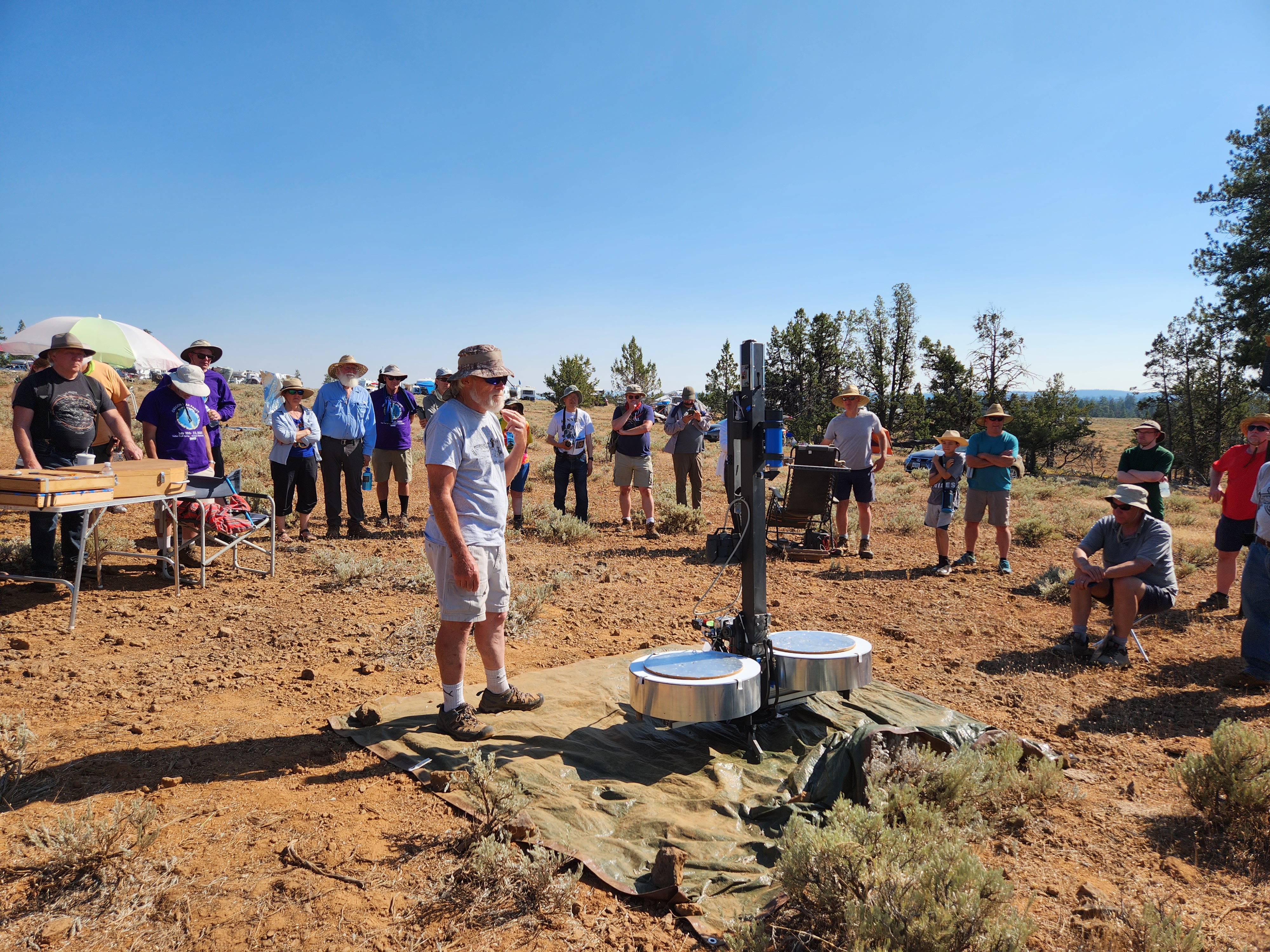
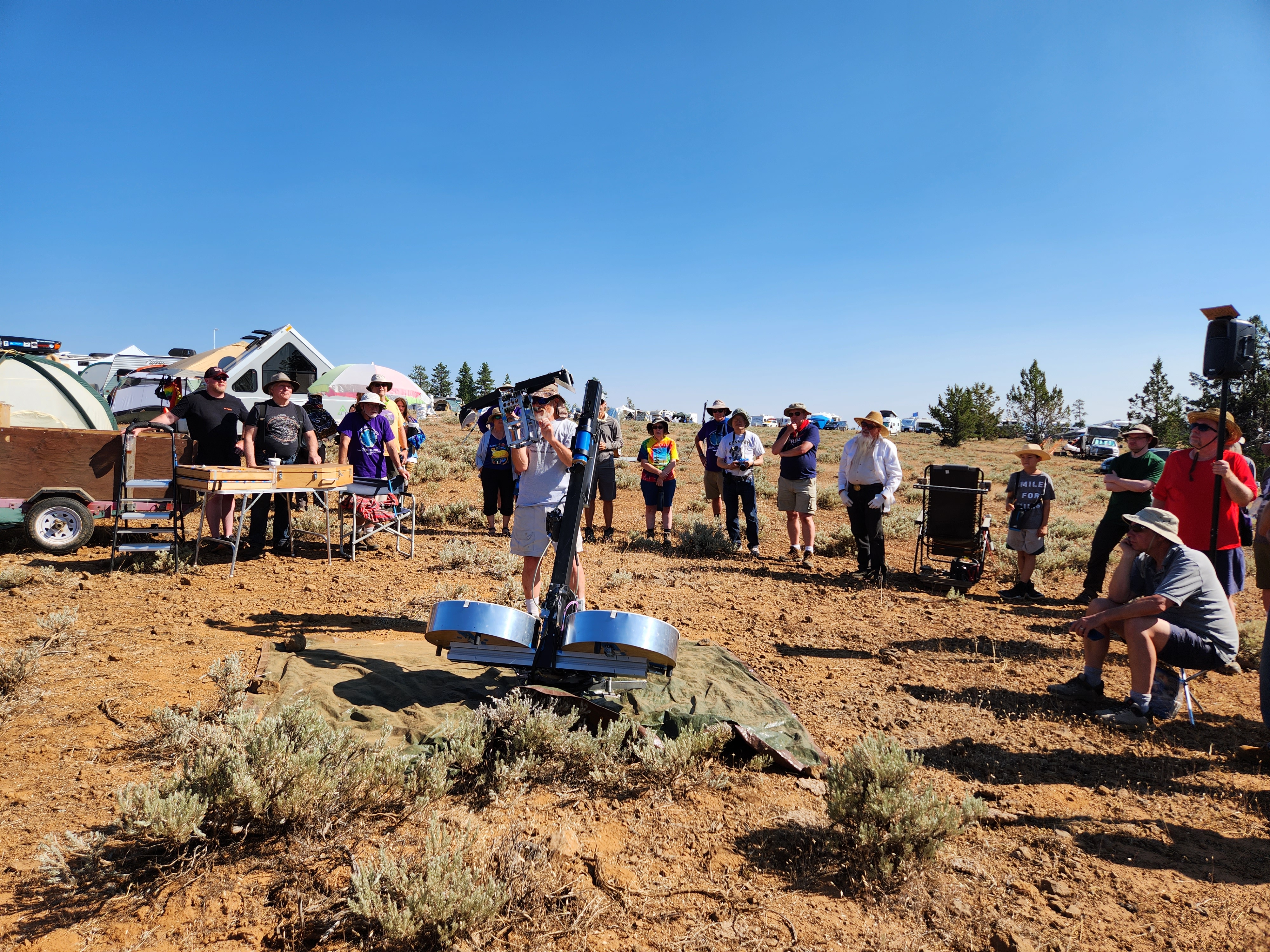
Frank Szczepanski 8 inch [20cm] (1998,2002)
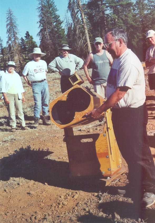
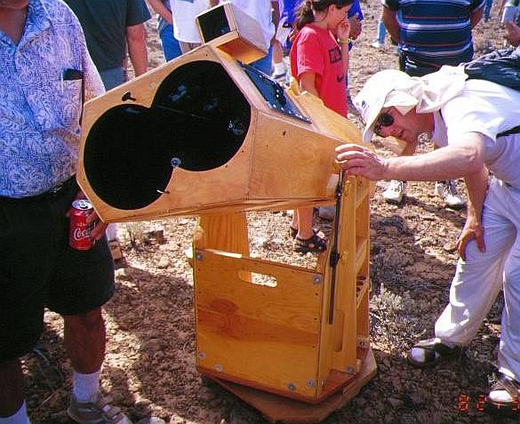
Frank Szczepanski 4 inch [10cm] (2014)
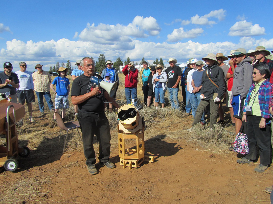
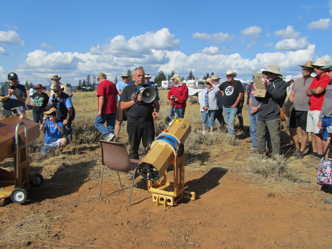
Frank Szczepanski 10 inch [25cm] (2019)
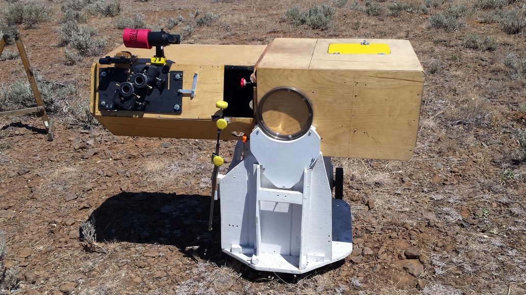
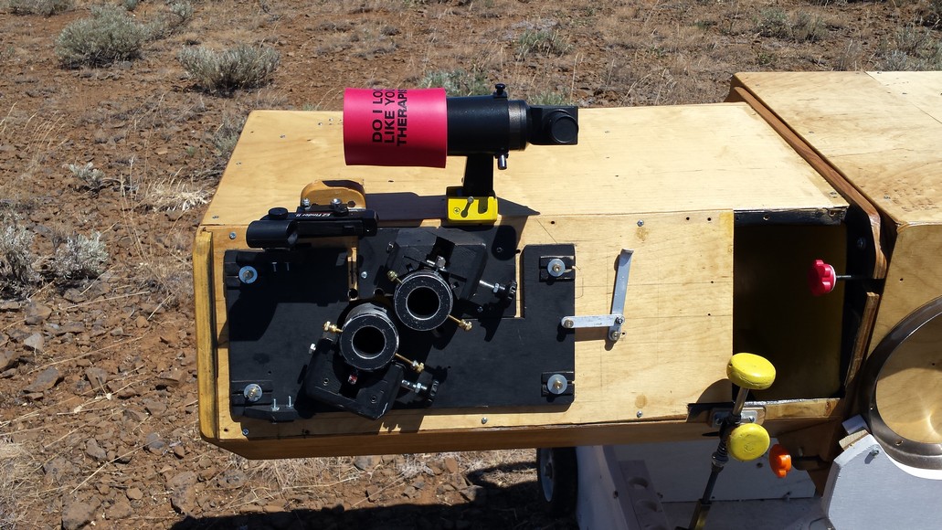
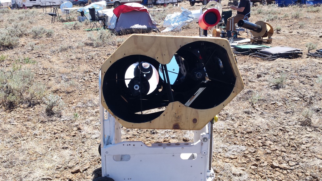
Frank Szczepanski unequal aperture 12 inch [30cm] and 10 inch [25cm] binoscope (2015)
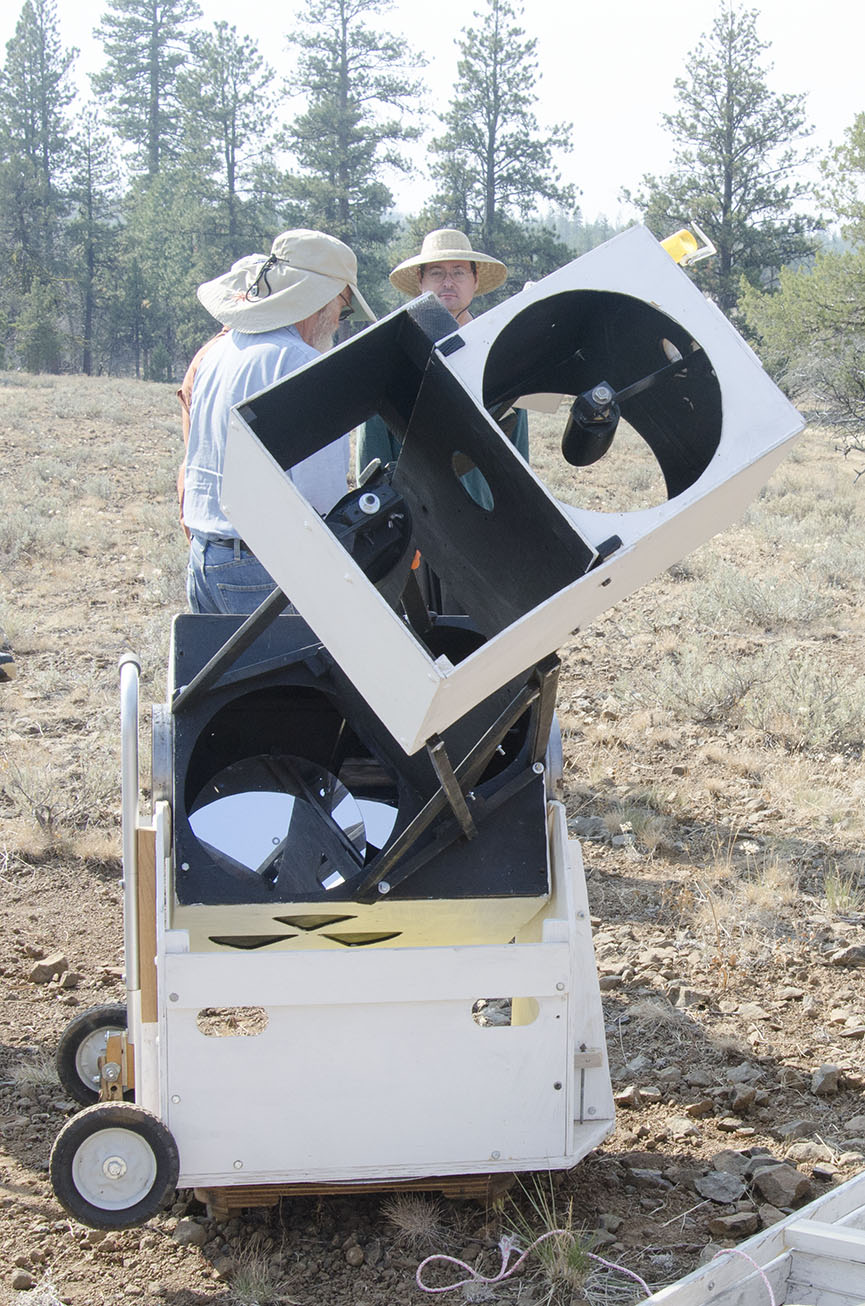
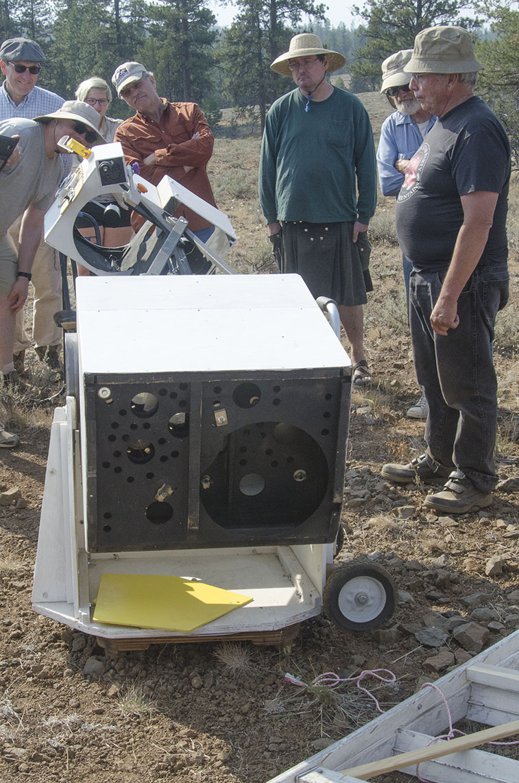
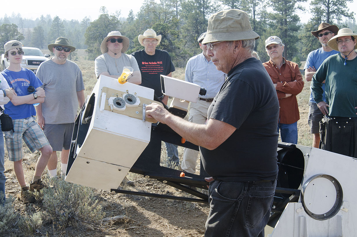
Jerry Oltion 12 inch [30cm] (2014)
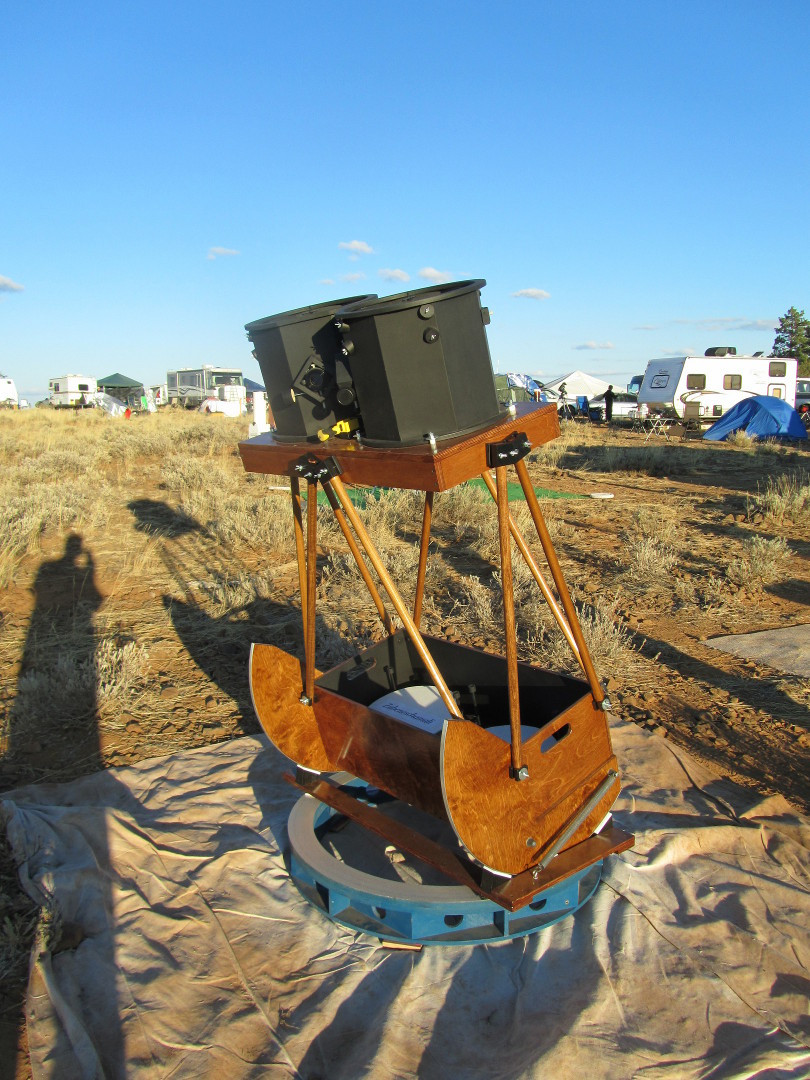
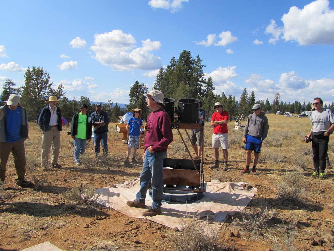
Frank's 8 inch and 4 inch, Jerry's 12 inch (2014)
Bruce Sayre 14 inch [36cm] (1999,2017)
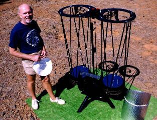
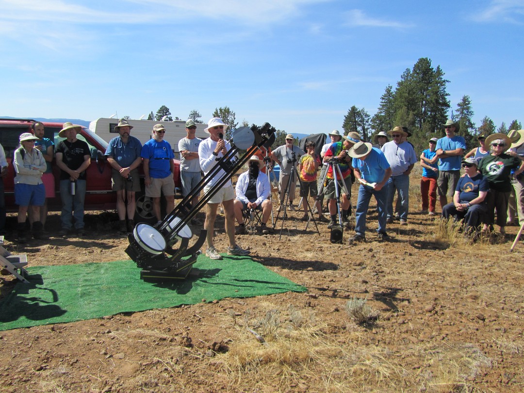
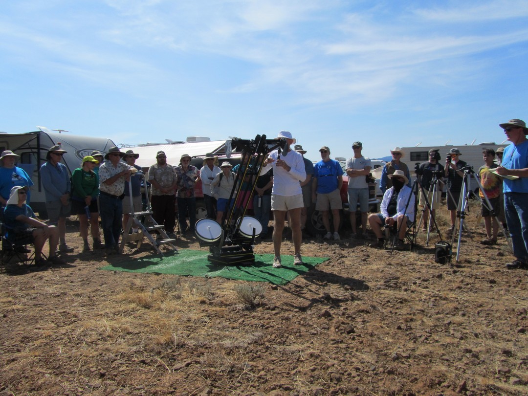
Bruce Sayre 22 inch [56cm] (2003,2005)
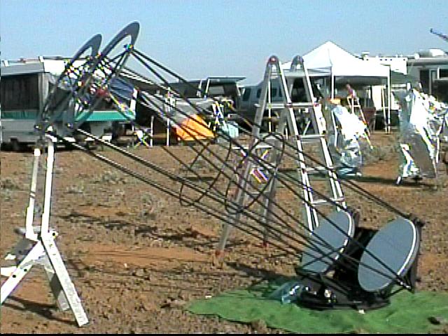
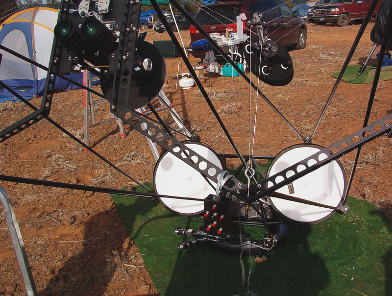
Jonathan Dubay 10 inch [25cm] (2016)
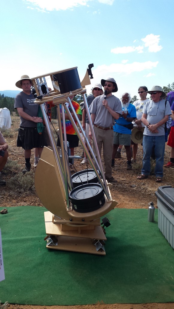


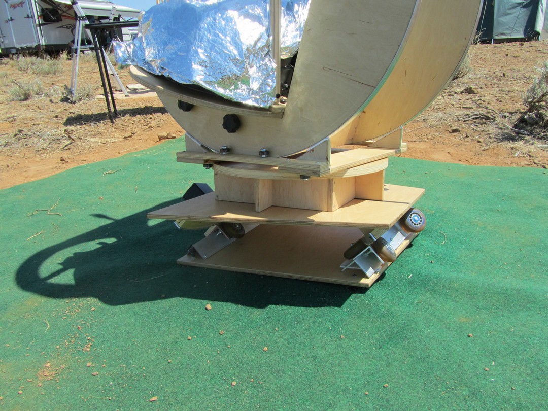
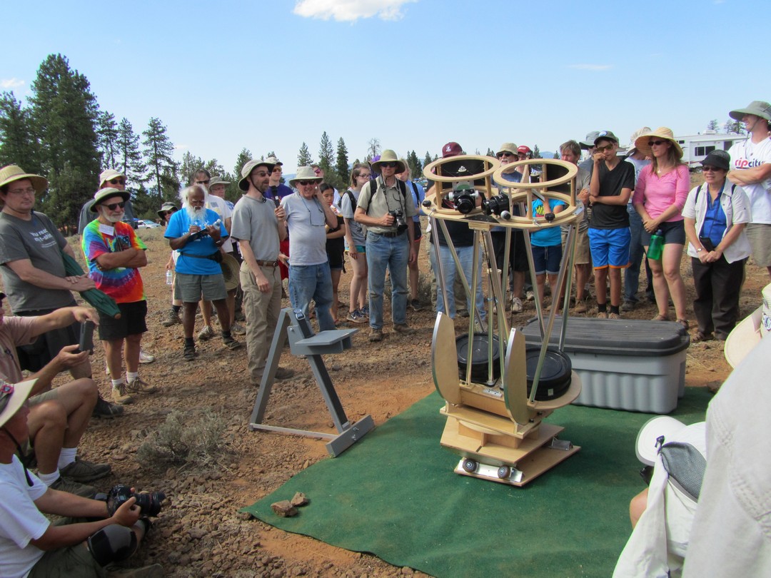
Robert Asumendi's 8 inch [20cm] 3D printed latest version (2019)
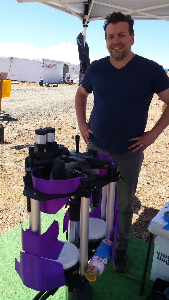
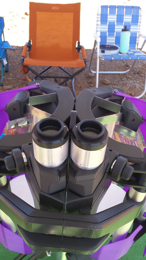
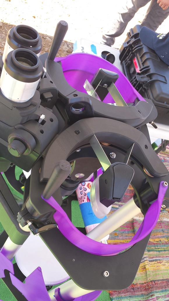
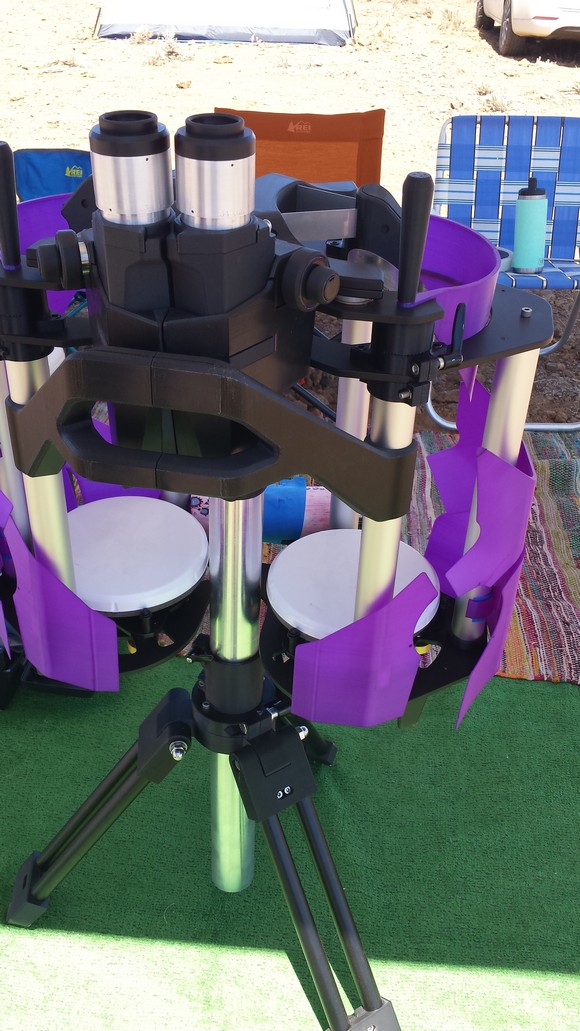
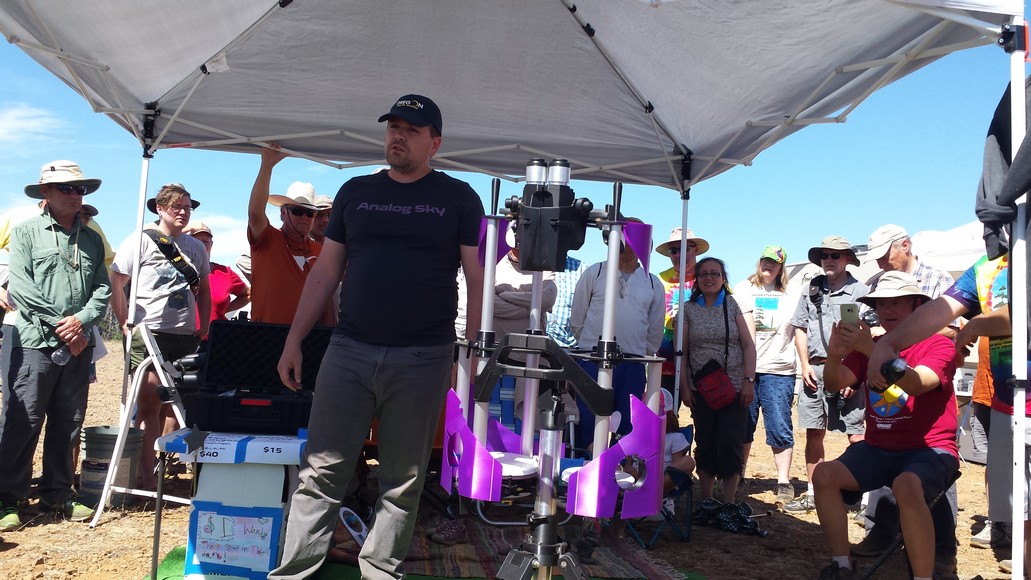
Robert Asumendi's 8 inch [20cm] 3D printed early version (2018)
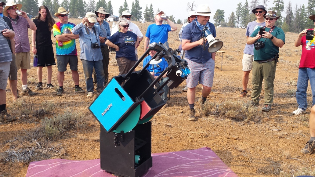
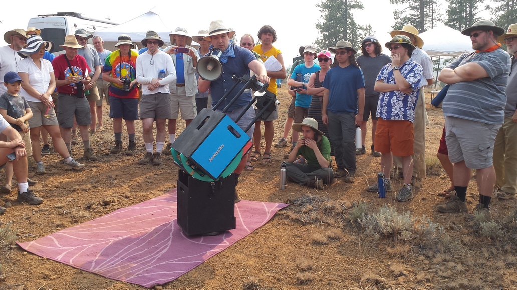
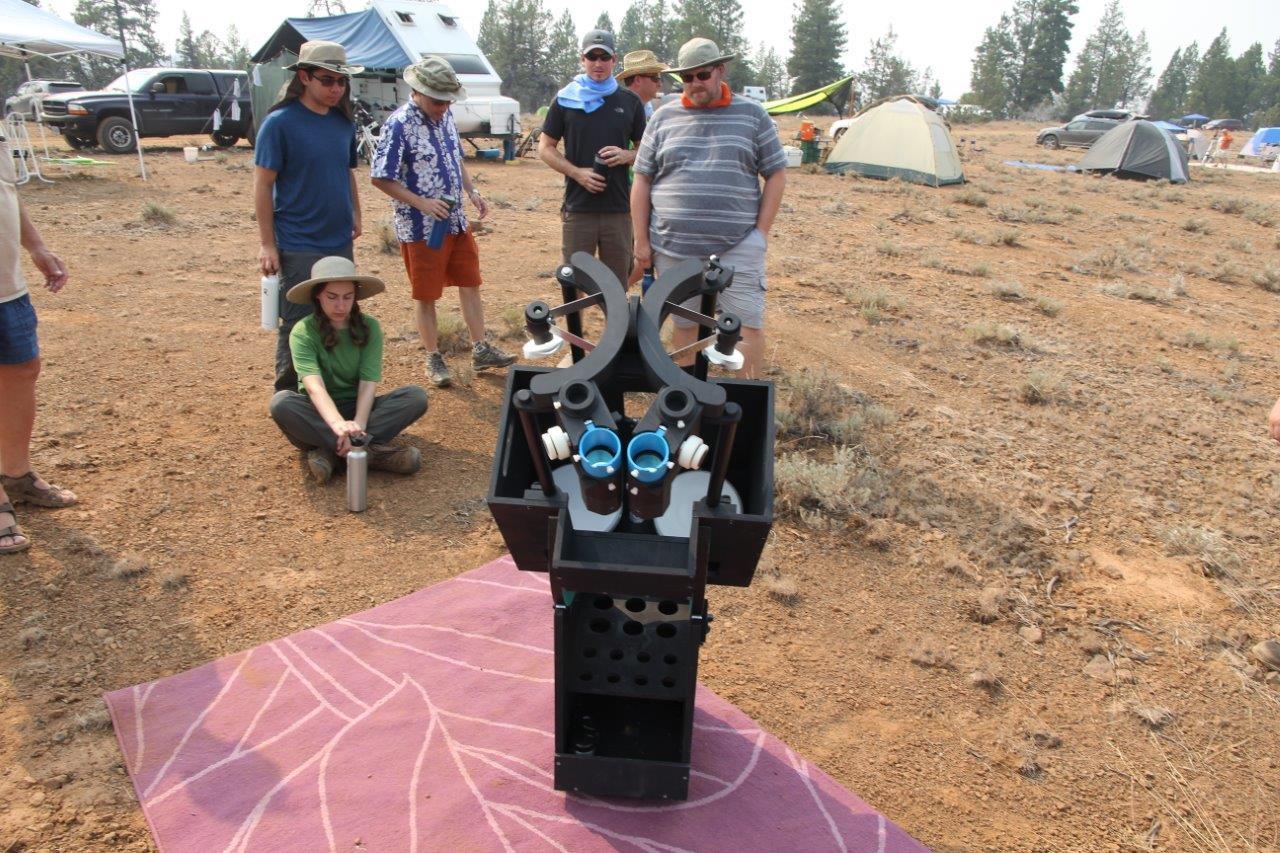
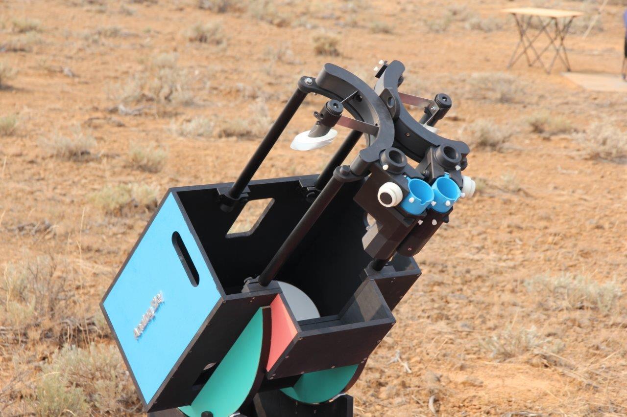
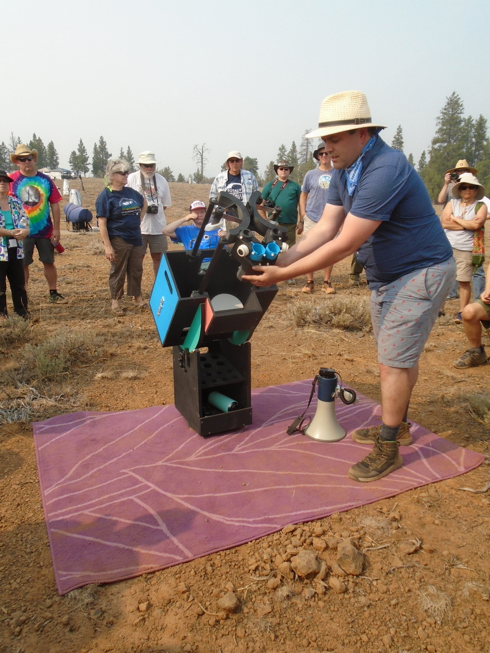
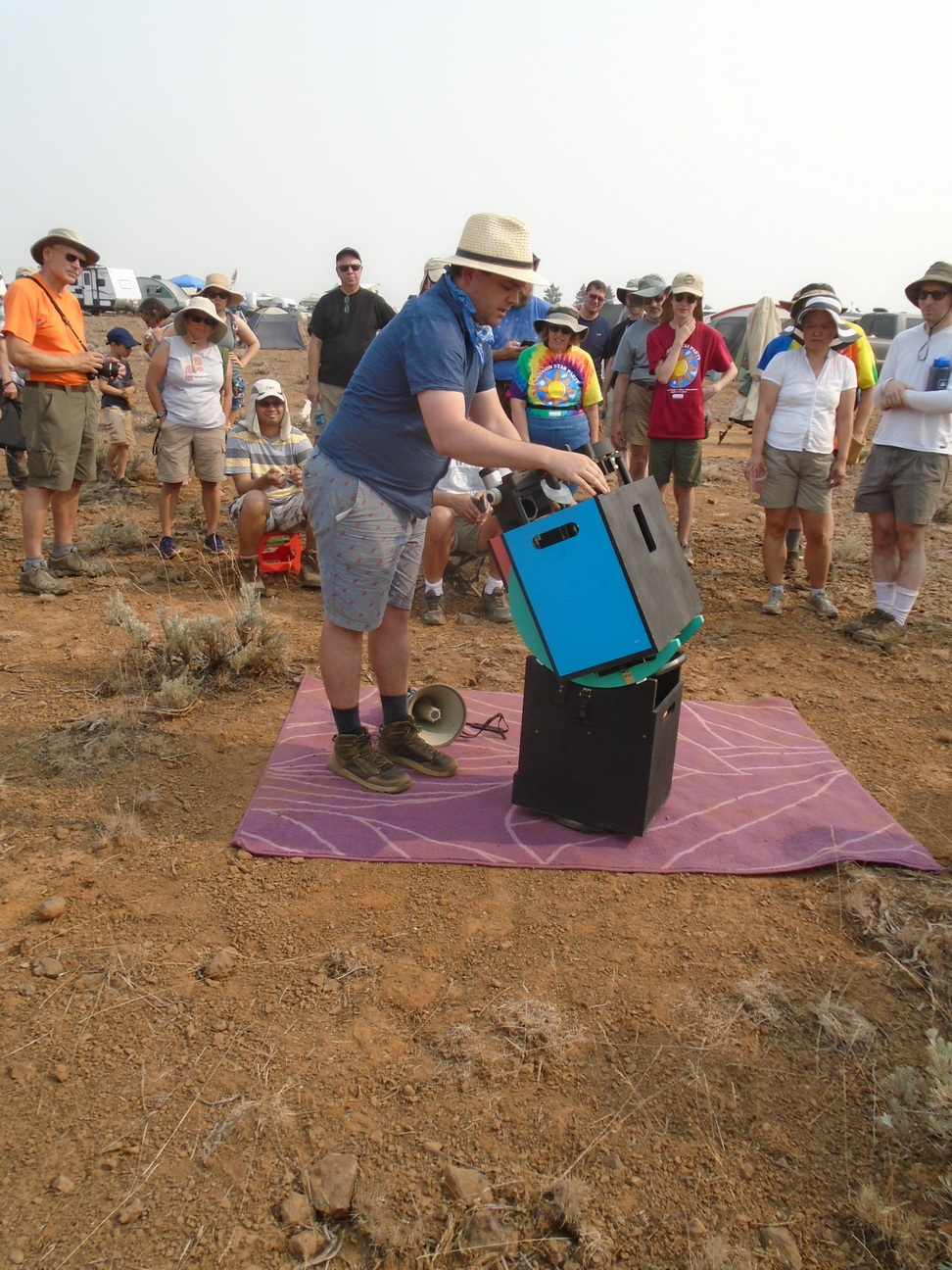
Bill Faatz, A.K.A. "Mr. Bill" on the CloudyNights forum 5 inch [13cm] (2015)
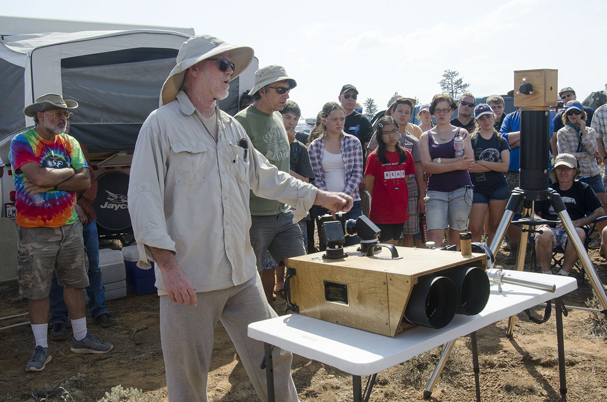
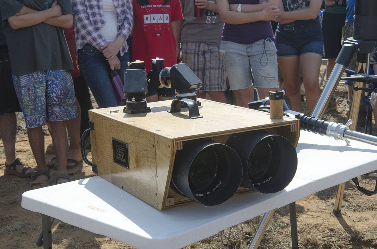
Hitoshi Yokoyama, Japan 76mm reflecting binocular (2015)
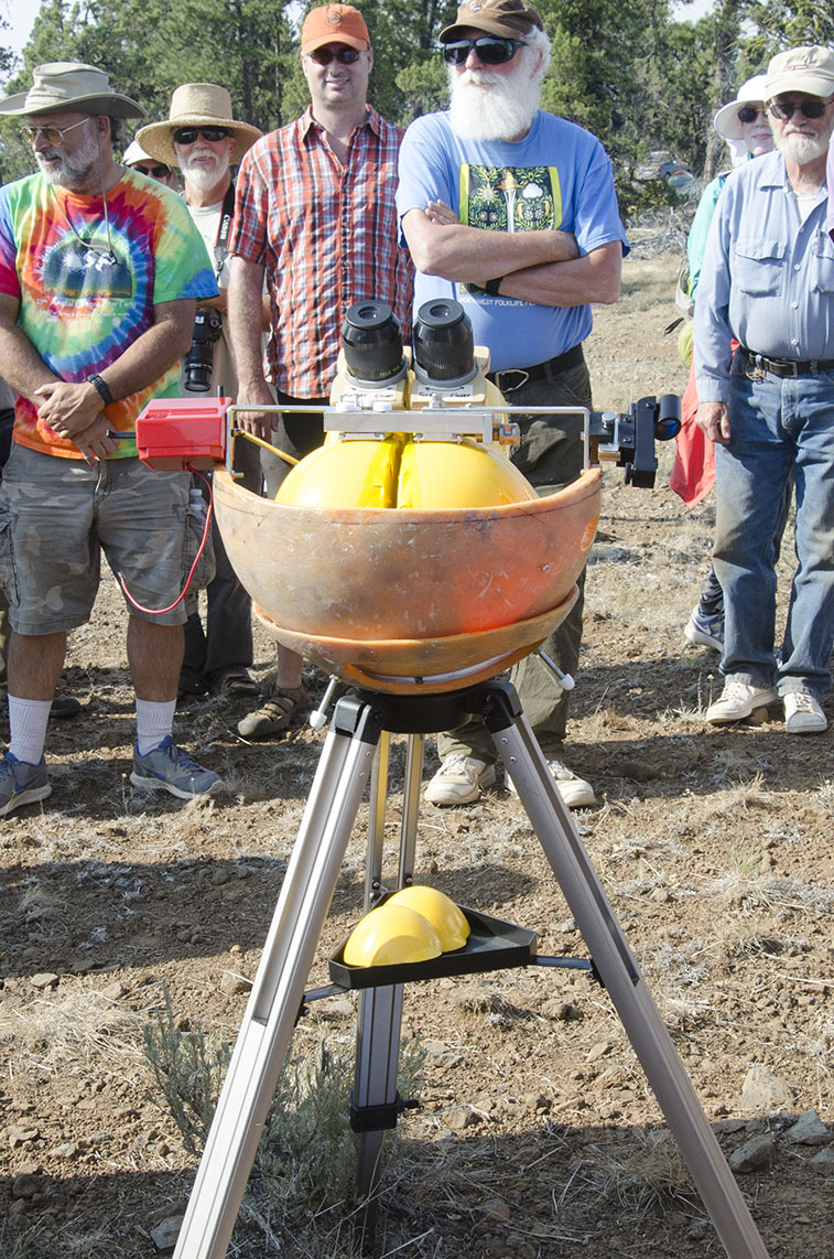
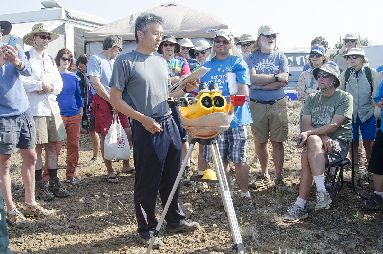
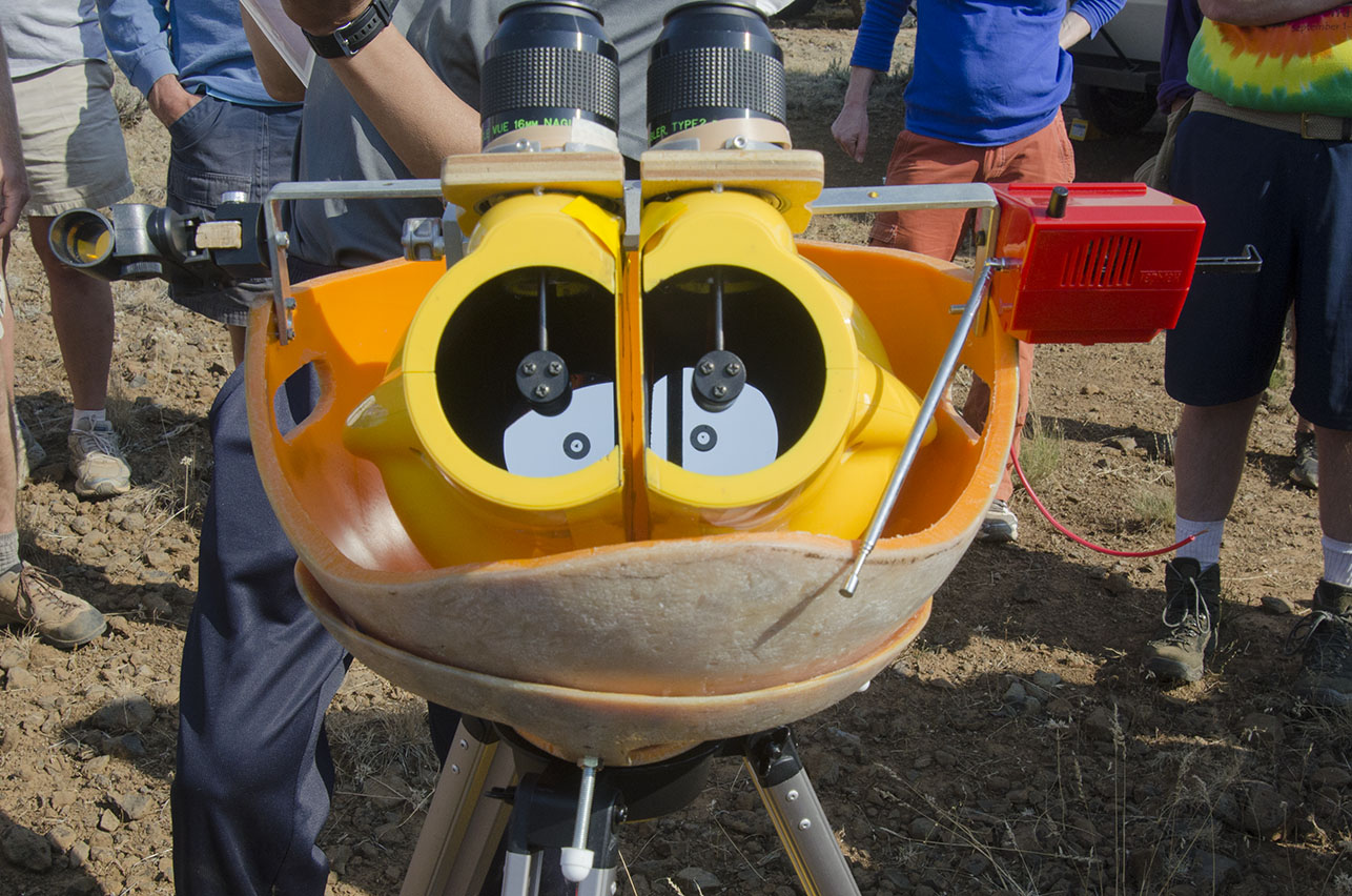
Steve Swayze, 12 inch F5 binoscope, RTMC and OSP (circa 1993)
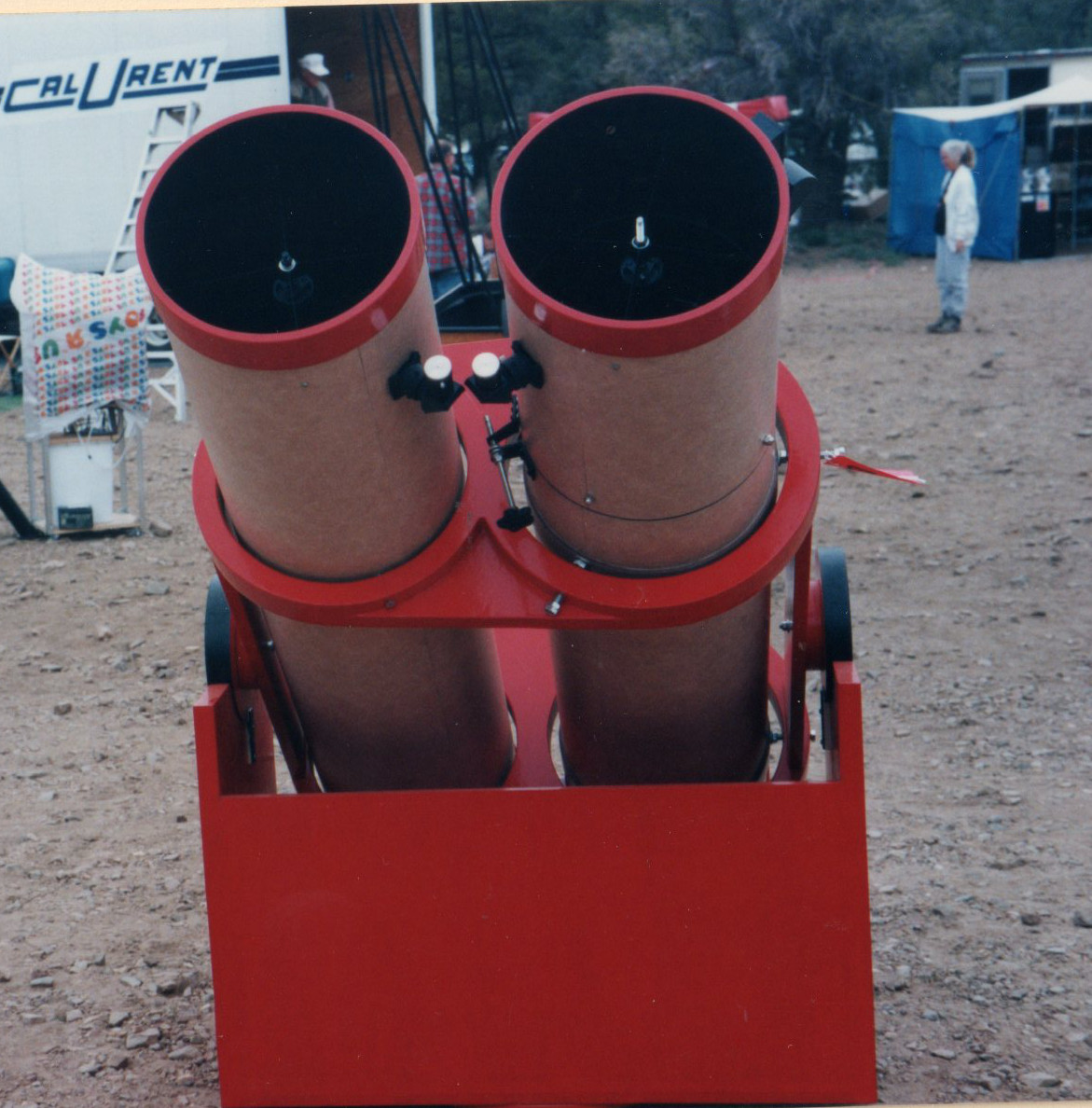
There are four optical path styles:
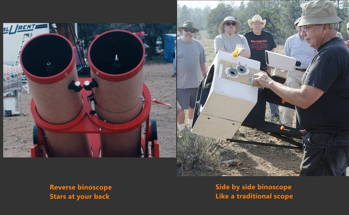
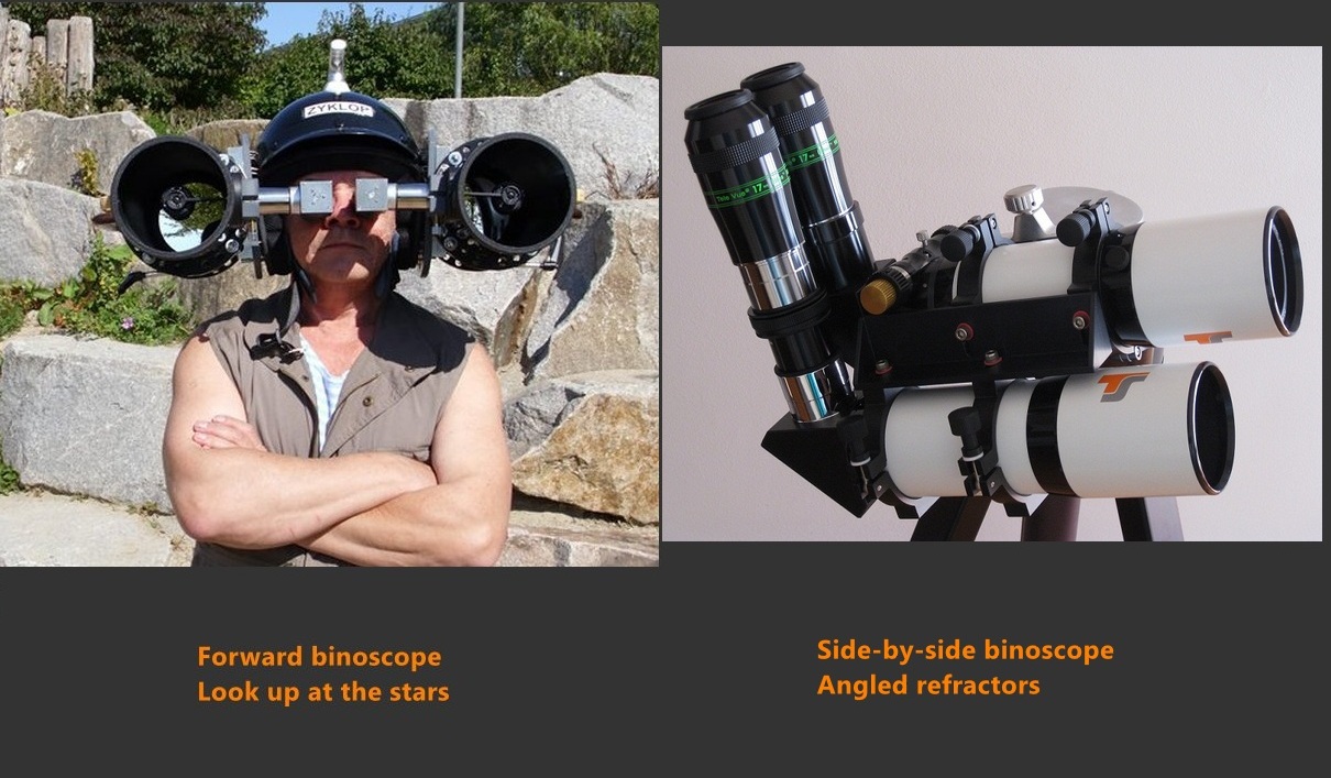
The overly large diagonal in the side-by-side design can be reduced in size by pushing up the more distant mirror, clipping the closer mirror slightly. The area gained by reducing the diagonal size is far greater than the clipped area. Additionally, the large diagonal can be reduced in size by lowering the focal plane into the closer mirror's optical path. The reduction in diagonal area compares to the area blocked by the lowered focal plane. Diffraction effects from the intrusive eyepiece barrels can be lessened by a baffle with curved edges. Here is the comparison for an 8 inch binoscope.
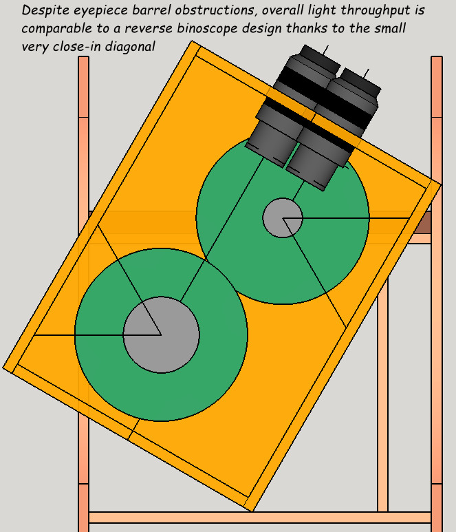
In the side by side design, the two mirrors do not have to have identical diameters. They do have to have identical focal lengths. Here is Frank Sczcepanski's unequal 10 and 12 inch mirrors binoscope.
IPD adjustments
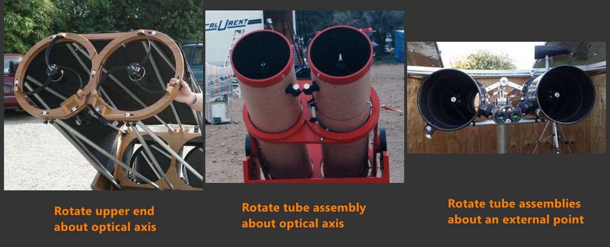
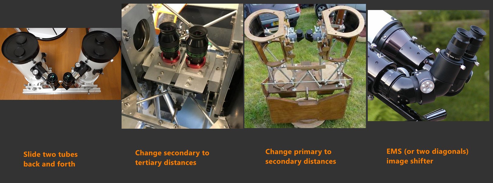
Diverging eyepieces can be used to alter IPD.
Vertical and horizontal merging
*** Here is a study showing how Eric Royer's adjustment of both primary and secondary can maintain collimation while making slight changes in aiming, allowing merging of the two images. The center of the field of illumination shifts slightly. See Eric Royer's detailed discussion. And my Sketchup model here.
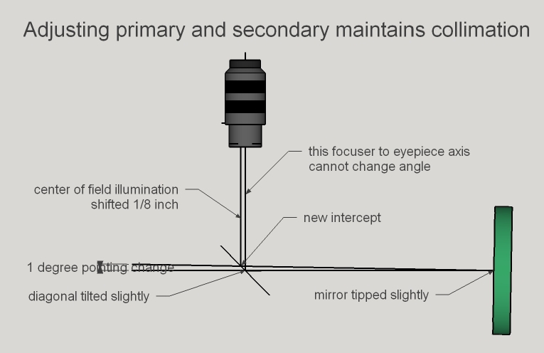
Focusing: adjusting the eyepiece to primary mirror's spacing so that the sharpest view is projected onto our eye's retina
Focusing mechanisms
Variations in altitude bearing placement and tube assembly designs
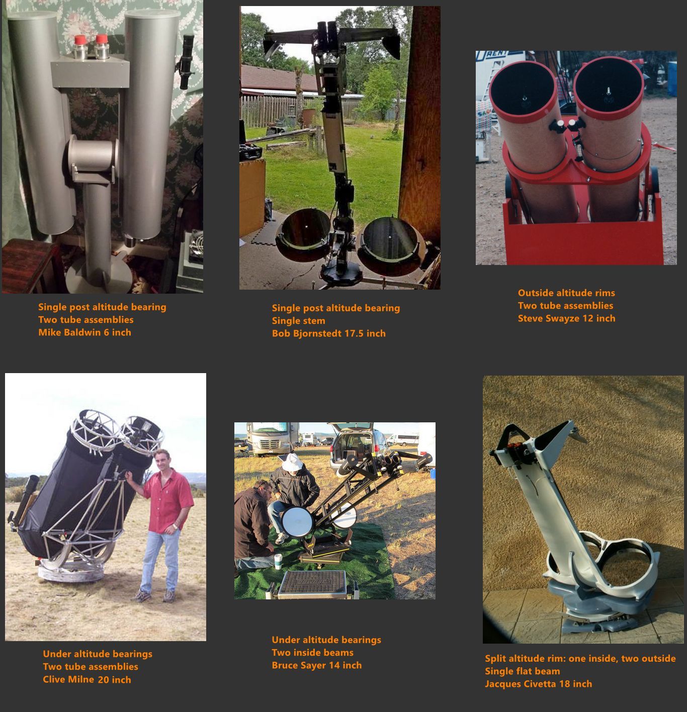
This gives us then the following design criteria to consider
Because of the design challenges and the imperative to innovate quickly and often, 3D printing is an ideal medium to design and build a binoscope.
Robert Asumendi in particular has demonstrated that a desk with computer is a fine substitute for a metal or wood workshop. Design a part, print it, inspect it, improve it, and repeat as often as desired.
links
Peter Abrahams has researched the history of the binoscope extensively.
In the above article, Peter mentions a binoscope from the ATM book series, book I. It was built by Mr. Hilmer Hanson of Holdrege, Nebraska, in the 1920's.
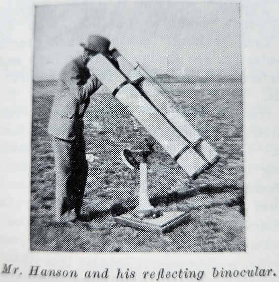
Peter also describes Herschel's binoscope design.
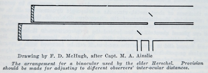
Since the advent of the Dobsonian era, Lee Cain of Houston Texas made several large aperture binoscopes using Coulter Optical mirrors in the early 1980's.
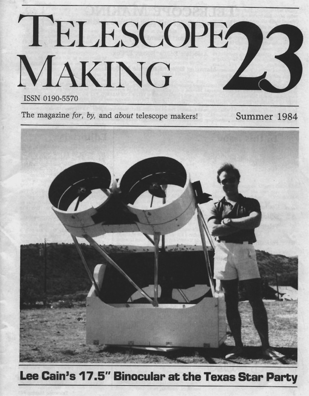
The Aussies got into binoscopes circa 2000. See links in my resources section below. Oregon amateurs have also built a number of binoscopes. See my binoscopes featured at the Oregon Star Party section above. Also see some of the European binoscopes in my resources section below.
I maintain a list the largest amateur binoscopes made here.
Commercially, JMI was the first to make and sell binoscopes. Today, Robert Asumendi's Analog Sky uses rapid 3D printed prototyping to innovate in the commercial arena.
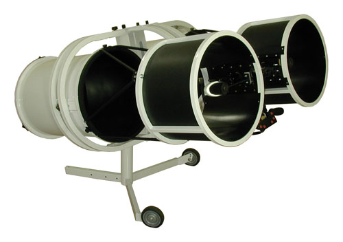
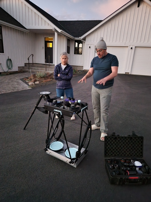
| Part | Weight | Distance | Vertical offset |
|
| |
| Results: | |
I like to use the mirror's forward edge to reference distances. So the mirror cell has a negative distance and the diagonal, focuser and eyepiece are at the mirror's focal length minus the diagonal to focal plane distance minus the sagitta.
To arrive at the tube clearance needed for the Dobsonian rocker be sure to set the tube's OD.
With today's heavy eyepieces and coma correctors, it is important to vertically offset the Center of Gravity to maintain balance as the scope swings upward.
Here's a table of tube types with links to further information, current as of October 2018.
Tube types vary greatly; a great deal of clever thinking. The details matter, for example, truss tube connectors. Open frame telescopes are susceptible to dewing unless the optics are heated as well and need attention to baffling. On the other hand, closed tubes can insulate the primary mirror keeping it from cooling down expediently.
Select a tube type
| Tube Type | Truss Count | Local Seeing Issues | Engineering Note | Examples |
Starting in 1992, I began building telescopes with a single upper ring. Here is a series of telescopes I built, showing how my upper ring design evolved.
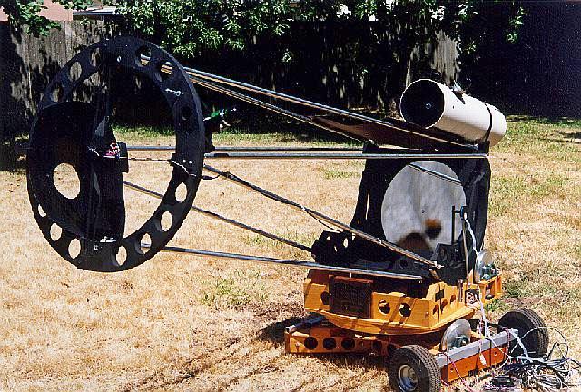
Ivar Hamberg in 1982 built the first amateur truss tube telescope. See Telescope Making issue 17. He used an 8 tube truss, attached to the inside of the mirror box. Here is a picture from a Spanish website

As you can see, it was quite revolutionary, enabling the transport of large Dobsonians in small cars.
The vast majority of truss tube Dobs are of this design. Another design that works nicely and looks elegant is Albert Highe's 3 truss arrangement. It is important to clamp the tubes, not letting them pivot on their connectors. Doing so increases the stiffness ~10x. Still the design sags another 10x over tradtional truss designs, so it is important to use larger diameter tubing. This image from a CloudyNights discussion.

There are other truss arrangements. Here are some to consider:
My 6inch F4 travel scope.
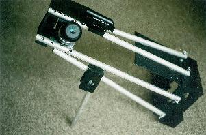
Jonathan Pogson's 3-2-1 hex arrangement (pictured is his binoscope prototype). From a CloudyNight discussion

Seth Jeleu's 6 truss arrangement.
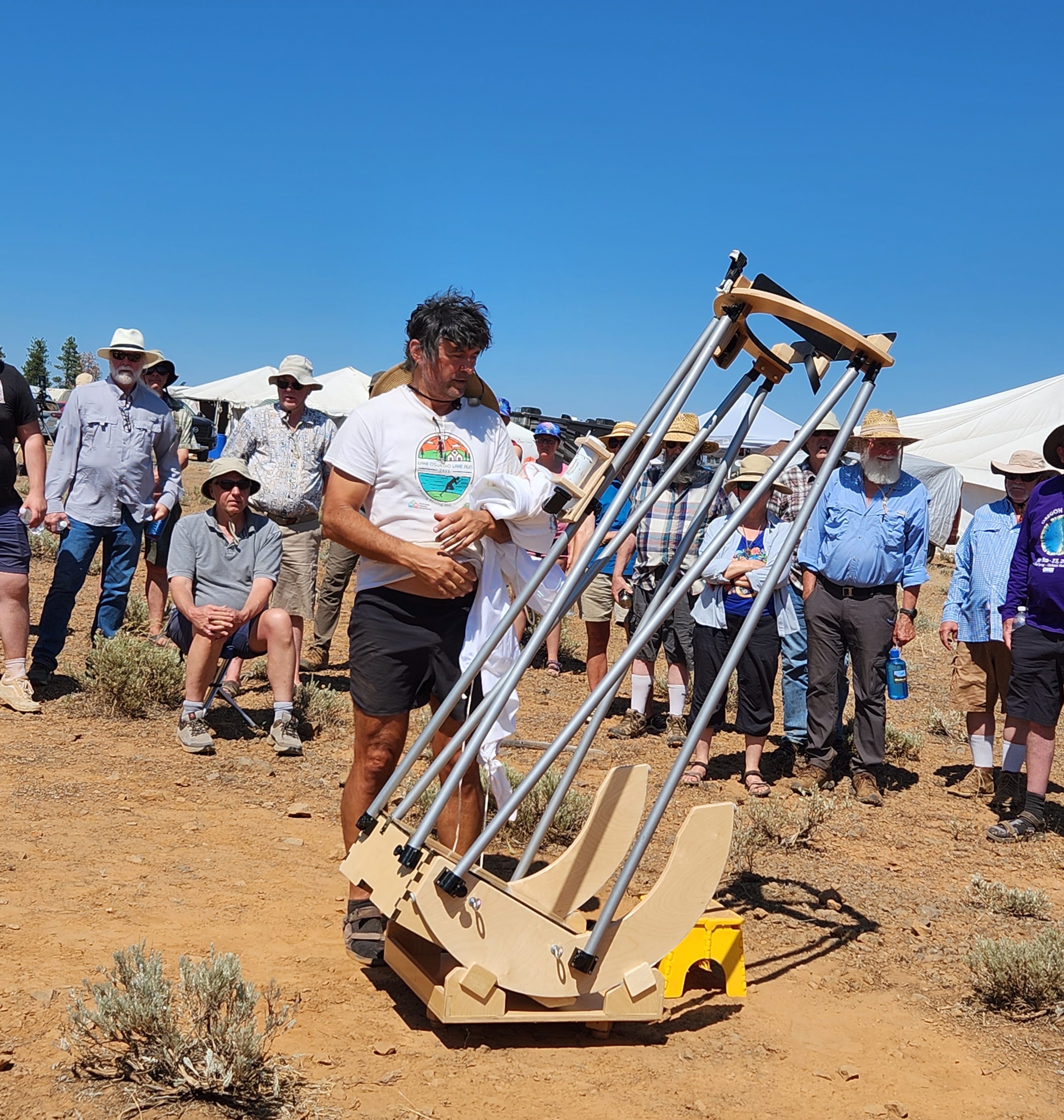
My 6 truss 20 inch Tri-Dob and 6 inch.
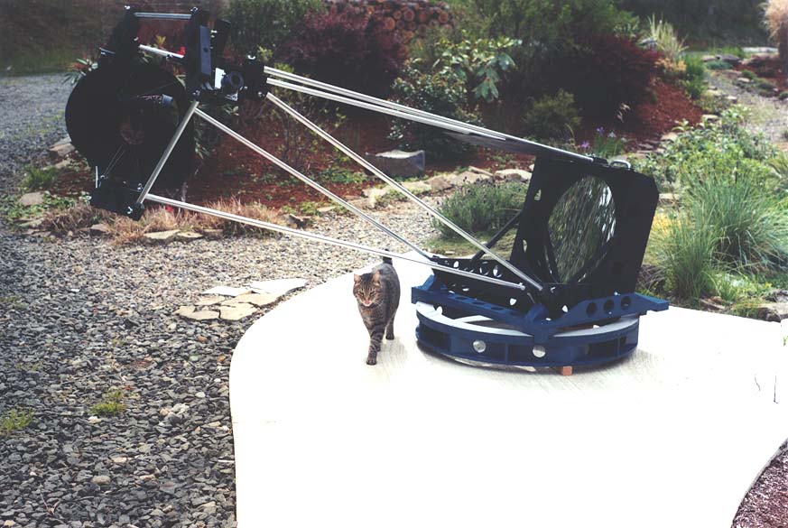
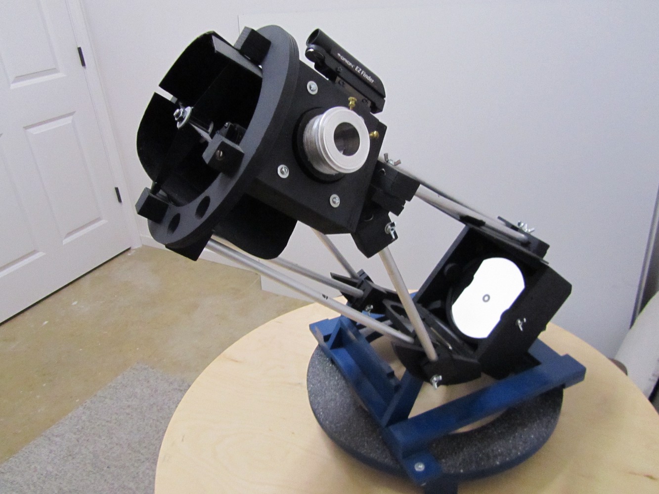
The 'A-frame' tube arrangement.
Alan Gillispie's two angled truss 8 inch
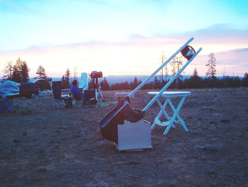
Two trusses vertically arranged. My 24 inch F5.5.
Two trusses arranged horizontally. A 17.5 inch scope from 1984's RTMC.
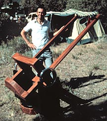
A single truss from RTMC.
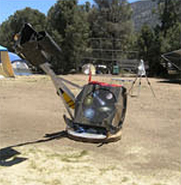
16 inch ultra light Dan Gray string scope
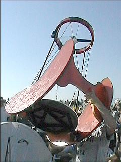
28 inch Dan Gray string scope
Don Peckham's Tensegrity telescopes (the inventor - see his webpages)
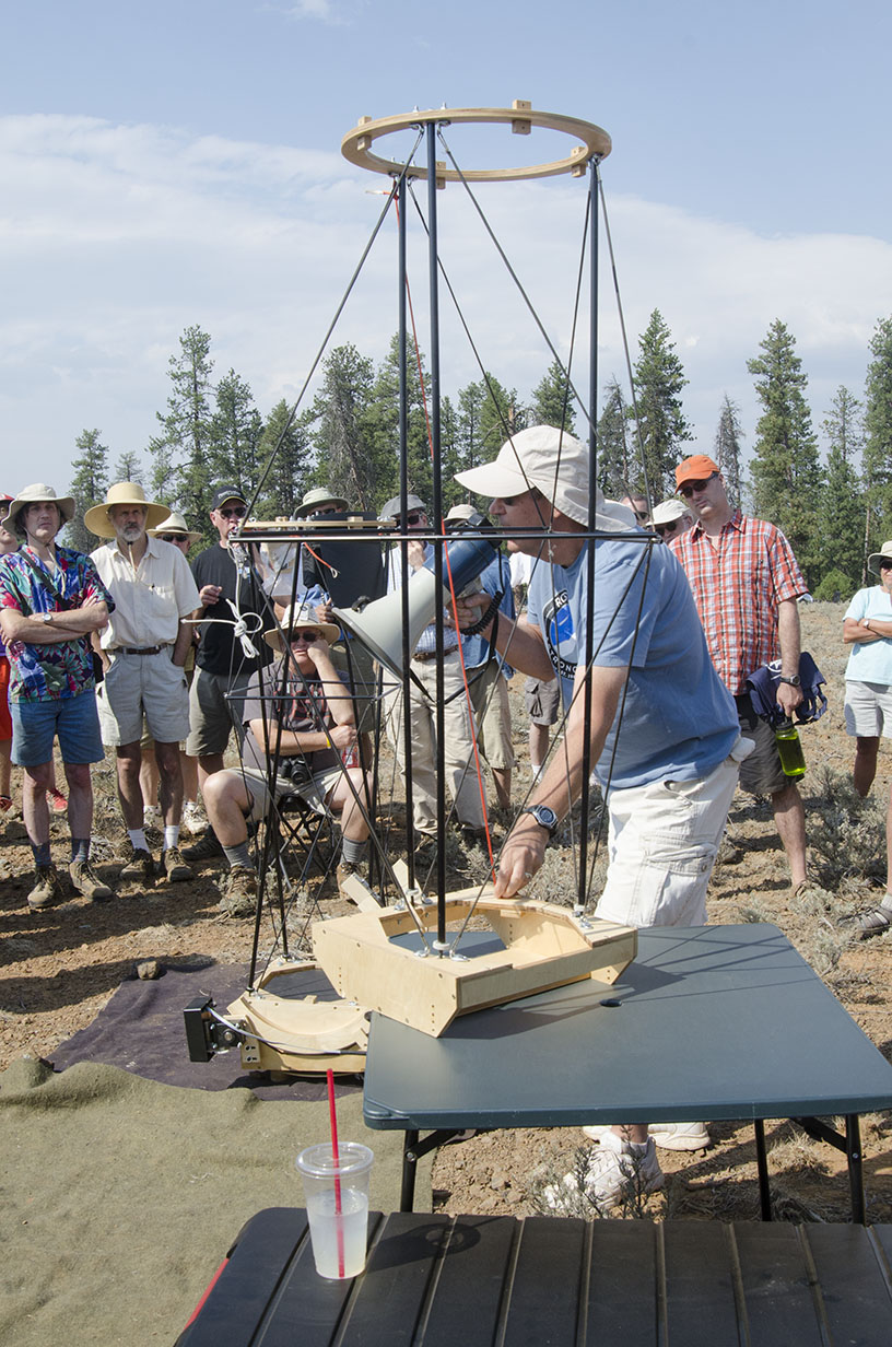
Rob Brown's Tensegrity scopes
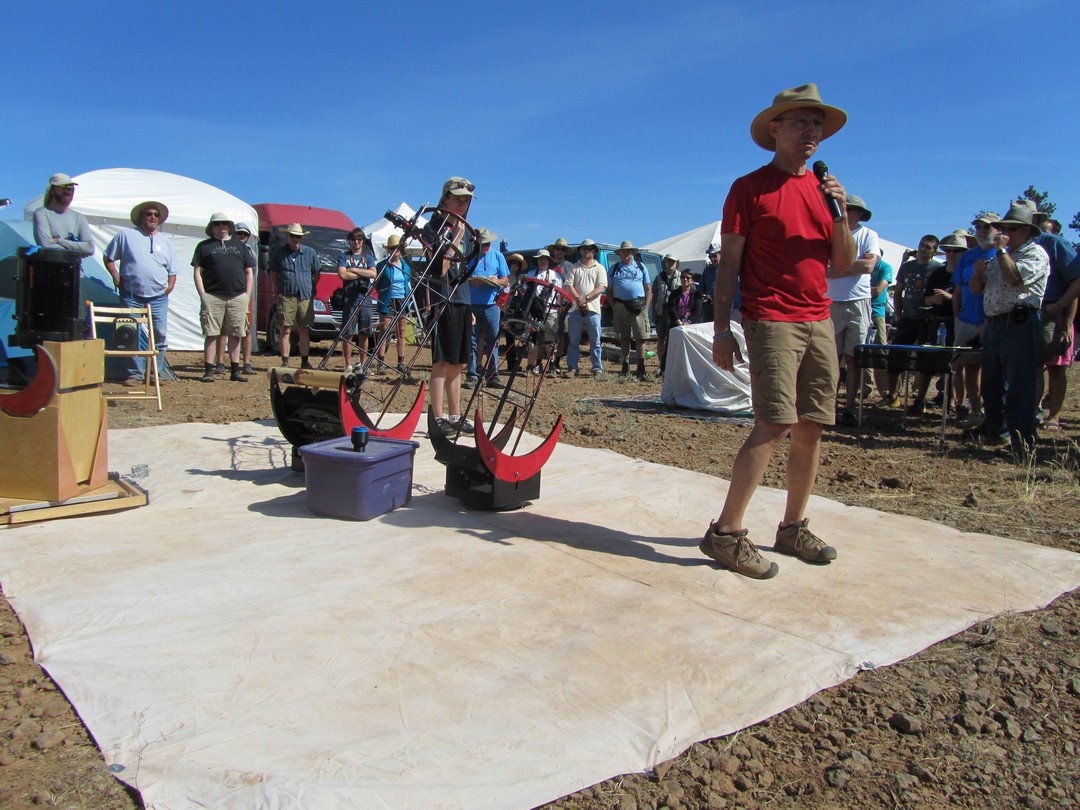
There are more. See the RTMC (Riverside Telescope Makers Conference) archives. Indeed, the traditional solid closed tube is just that: a single tube that happens to encompass the optics.
Three mount types dominate: the Dobsonian altazimuth rocker mount used for portable and larger aperture Newtonian reflectors, the German equatorial mount for smaller scopes that require sidereal tracking and the fork mount for commercially manufactured Schmidt-Cassegrains. But these are not the only mount designs available. Another mount design might prove a better fit.
Equatorial mounts are polar aligned needing only a single motor operating at a constant speed to track the sky. There is no field rotation (other than a minuscule amount due to refraction at the horizon). Other mounts are either hand pushed or require more complex varying speed motors and incur field rotation.
Here's a table of mount types with links to further information, current as of October 2018.
Select a mounting type
| MountType | Primary Axis Access | Move Past Primary Axis | Primary Axis Fully Rotates | Meridian Flip Possible | Meridian Flip Required | Notes |
Vibration is a particular concern to telescope users. Not only are telescopes prone to vibration thanks to heavy weights at one or both ends, but whatever vibrations are present are highly magnified when looking through the eyepiece. That's why telescopes have massive mountings - to combat vibration. In the old days (1960's), the most popular type of amateur telescope was a 6 inch Newtonian on a pipe mount. The rule of thumb was to focus, then stand back and count to twelve to let the vibrations quiet down. Nowadays amateur telescopes are typically mounted on a Dobsonian mount - a form of an altazimuth mount much like a battleship's guns. An excellently designed and built Dobsonian telescope will quiet down in one second or less.
There are three sources of vibration: wind, hand touching, and motor drives. As the wind buffets a telescope, the scope's cross section, substantial thanks to its length, absorbs a surprising amount of energy, moving the telescope tube about its center of gravity imperceptibly. When the wind calms or momentarily swirls, the tube will spring back, setting up a vibration. Similarly when hand touching a telescope to focus an eyepiece or to make a positional adjustment, the telescope will spring back when the hand is let go.
Telescope users care about three principal characteristics of telescope vibration: the amplitude, the frequency, and the dampening time. The amplitude is the amount of back and forth movement. This can be measured at the eyepiece in arc-minutes or arc-seconds where the planet Jupiter is on average 45 arc-seconds of size. The frequency is the number of vibrations per second. Most telescopes vibrate at a low enough rate to be estimated by counting the shakes over a second or two. The dampening time is the amount of time in seconds that it takes for the vibration to come to a halt. An ideal telescope will have small amplitude and short dampening time. For instance, a Dobsonian telescope might have an amplitude of 1 arc-minute, a frequency of 5 Hertz, and a dampening time of 1 second.
Wooden and aluminum truss Dobsonian telescopes typically have a frequency of several Hertz, that is, they vibrate back and forth several times a second. The relatively slow speed is due to large masses at some distance from the center of gravity. The frequency can be increased by making the upper end lighter, by making the mirror box lighter, and by shorting the tube. Increasing the frequency is desirable as the overall dampening time will often shorten.
Vibration is absorbed by the ground and by the mount itself. A slightly soft surface such as grass or dirt will absorb vibration much better than concrete. But if the ground is too soft then it may act to amplify slow telescope vibrations. To promote absorption, sorbothane pads should be placed between the mount's feet and the ground. These pads absorb vibrations, prevent vibrations from traveling back into the telescope, and give the mount a slower characteristic resonant frequency. Wooden and aluminum mounts are somewhat flexible and therefore have more vibration absorbing ability. The frequency is lower with these mounts. In addition, these mounts suppress harmonics. The sorbothane pads respond slowly to vibration and therefore lower the natural frequency of the mount. Dangling chains from the upper end of the tube absorb vibration as they clang together. Another more common tactic is to place vibration absorbing material such as sorbothane-, rubber, and leather between critical components of the mount.
While the hand can be a source of vibration moving and focusing the telescope, the hand can also be used to absorb vibration by touching the upper end while viewing.
Vibration caused by wind can be significantly reduced by removing as much as possible of the telescope tube's cross section. Instead of the completely encircled upper cage and shroud, amateur telescope makers have used single ring upper ends drilled with holes without shrouds to good effect in windy conditions.
This will expose the diagonal to the wind, consequently an ordinary spider may no longer suffice. In windy conditions, the heavy diagonal causes the diagonal holder to very rapidly vibrate about the spider center in a back and forth rotational arc. Splitting the spider so that the four vanes come to two points forming what looks like two 'V's that are not quite touching, removes the ability of the diagonal to rotate about the diagonal axis.
Finally, the motor tracking system can induce vibration. Any change from a completely smooth motor movement can induce vibration. This can come from the motor, from the motor coupling, and from the gearing. Very rarely if at all does the gearing cause vibration. But if a repeating or periodic error in the gearing is bumping or throwing the scope, and if the frequency of this error coincides with the natural resonant frequency of the mount, vibration not only would be induced but also amplified.
A coupler between the motor and the gearing is designed ease misalignment of the shafts and possibly absorb motor vibration. However even with a flexible coupler, badly misaligned shafts can cause vibration as they spin. The coupler itself can induce vibration also. If it is flexible, it might tighten and relax on its own accord, causing a sporadic jitter at the eyepiece. This can occur when the friction to rotate the output shaft is significant compared to the force required to twist the coupler. Here the coupler will tighten until finally it can transmit enough torque, at which point the shaft will skip ahead and the coupler will relax and shaft movement will cease until the coupler is would up again. The coupler can also indirectly cause vibration if the motor control feedback is on the opposite end of the coupler from the motor. The feedback algorithm will have a varying delay caused by the twist up of the coupler introduced, causing it to feed large control signals to the motor first one way, then the other way. These control signals can cause the motor to transmit large oscillatory movements through the coupler into the telescope mount.
Typically in servo motor systems, the overall gearing reduction is less, putting a premium on the coupler. So couplers for servo systems should be rigid, particularly if geared lightly and if the motor control feedback is on the other side of the coupler. The coupler can be somewhat flexible in highly geared servo systems and in stepper motor systems. The coupler should be as short as possible otherwise the windup effects mimic a long spring.
With modern servo systems, the control system can induce very slight vibrations. The pulse width modulation often used to control the motor velocity might be felt. The control system algorithm may have periodicities and the feedback loop may induce vibration under certain load conditions.
With stepper systems and their typically highly geared drivetrain, a somewhat flexible coupler can help smooth out any jerkiness in the stepper motor as it moves from step to step. Stepper motors snap from step to step when operating in fullstep or halfstep mode. This causes a jittery motion in the eyepiece that can be quite objectionable. A good test for this is to turn the drive off and on to see if there is any difference in the image quality. Another way to test is to put your fingers lightly on the eyepiece. Jittery and higher speed oscillations can often be felt, if not downright heard by the ear.
Metal tubed telescopes such as refractors don't have the natural frequency absorbing characteristics of wood and aluminum Dobsonian mounts. Metal tubed telescopes also tend to not only vibrate at the lower frequencies caused by the entire tube shaking, but also tend to vibrate at higher frequencies and at harmonics of lower frequencies. This is manifested in the eyepiece as a very high speed wobble, perhaps only detectable by a frame to frame analysis by a camcorder, by the drive off and on test, or possibly by the finger test. Ideas to try to cure high speed vibrations include placing a piece of damping material between tube and cradle, significantly beefing up the mount, and not allowing potential sources of vibration to occur. These include stomping around the scope, wind, pulling and shaking of cables, and nearby car and rail traffic.
The ballscope is a wonderful mount; it commands a loyal following. With a single push the scope can move in both axes and rotate the eyepiece to a comfortable viewing angle. And there is no overhead 'Dobson' hole at the zenith, the bane of altazimuth scopes.
Did you know that Russell Porter once sketched an all-in-one ballscope/dome for the 200 inch Palomar telescope?
Ballscopes can track. Norm James (San Diego, California) in the late 1960's devised a motorized polar axis attached by a suction cup on his 'spheremount'.
Circa 1990 Alphonse Pouplier (Belgium) invented a two drive wheel and two motor 'crossed parallel' mounting that tracked, slewed to an object and tracked satellites (August 1993, Sky and Telescope magazine).
Pierre Lemay (Quebec) in the mid-1990's devised a polar oriented two roller drive system.
About 2010 Jerry Oltion independently invented a single motorized polar axis drive system that he calls the TrackBall.
The size and weight of the ball becomes prohibitive in scopes larger than 20 inches [0.5m] aperture.Here are my ideas to modify the ballscope for larger apertures. First, the standard ball scope: a ball for pointing with the attached upper telescope tube:
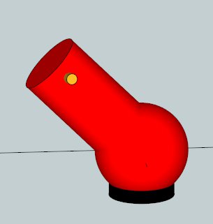
As you can see, the ball is about twice the aperture. For a 20 inch [0.5m] scope, the ball size would be approximately 40 inches [1m] but with careful thought as Pierre Lemay has demonstrated, it is possible to use a ball as small as 30 inch diameter. Otherwise such a telescope would be difficult to transport.
What would the ballscope look like if we start removing unused sections of the ball? If we give up pushing the scope all the way through the zenith to the far horizon and instead allow a modest movement through the zenith to cover 'Dobson's' hole, then the trimmed ballscope might look like:
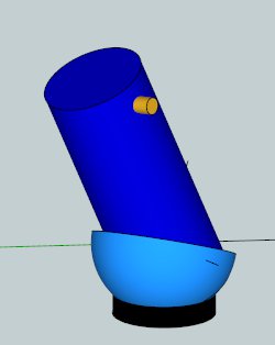
Here's Frank Szczepanski's hemi-ballscope 8 inch f/5 which uses a half sphere from a barbecue lid and a plain old 5 gallon plastic bucket for a base.
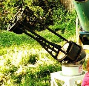
In this design the scope must be pushed around to reach the far horizon. However, large Dobs are often built with mirror mounts that use slings or two bottom edge supports at 90 degrees which preclude moving from horizon to far horizon by pushing through the zenith.
The ball is still too large but its weight has been cut in half. Let's keep going by acknowledging that in very large scopes, the eyepiece points out the side of the scope roughly horizontally within an angle of +- 20 degrees or so. Now the doubly trimmed ball scope might look like:
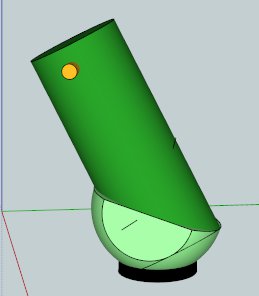
The ball has been trimmed severely to a manageable size and weight. In fact, other than the extra effort to make the smooth spherical surface, it is about the same dimensions from side to side as a Dobsonian styled altazimuth mount. But unlike the Dob we can push through the zenith forbidden zone and rotate the focuser to a comfortable viewing angle.
Trimming the ball to a saucer shape and adding altitude bearings for motion
up and down results in the following design:
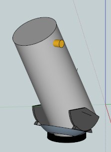
In this design the Dobsonian rocker box has been replaced with a curved saucer or Frisbee shape with an optional hole in the middle to allow the tube to swing through. The saucer acts to close Dobson's hole and allow the focuser to be adjusted to a comfortable angle. The altitude rims will need stops to keep the scope from sliding off. This has been demonstrated successfully by amateurs, e.g. see Rob Adam's Rob-a-Dob.
It is also possible to position the ball somewhat up the tube assembly. Then the telescope looks like:
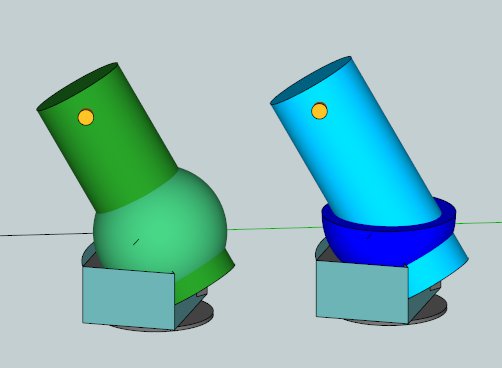
Here's Frank Szczepanski's 4.25 inch slipped ballscope whose lower tube is from a round ice bucket and a sauce pan and chunk of lead that extends through the opening in the brown wooden box.
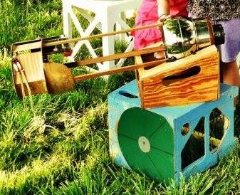
At the cost of a rocker box and the customary azimuth motion of a Dobsonian telescope, we can push through the zenith hole a few degrees and rotate the focuser to a good viewing angle at will. The rocker box contacts the ball at three points so the front panel needs reinforcing as shown and the side panels need trusses to not split apart (not shown).
These variations on the standard ballscope design show how the aperture limitation on ballscopes can be overcome.
Taking a completely different tack, the ballscope can be modified in an interesting and elegant fashion.
Let's start again with a side profile of the standard Dobsonian showing the telescope pointed horizontally and vertically:
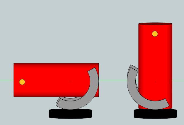
For large scopes with lighter primary mirrors, the altitude rims can be surprisingly large. It's possible to compress the altitude rims into a smaller elliptical shape, like a sleigh:
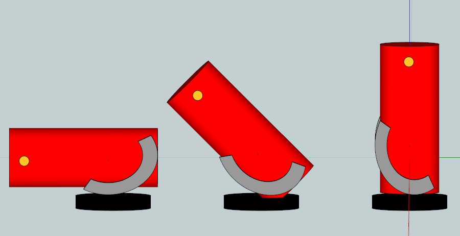
Besides the obvious squeezing of the altitude bearings, something else very interesting happens: the tube assembly slides backwards as the telescope points down to the horizon. This means that elliptical bearings can handle telescopes when the center of gravity is located uncomfortably further up the telescope tube. Explained differently, the center of gravity slides vertically downward as the scope transitions from pointing at the zenith to pointing at the horizon. The consequence is that the altitude bearings can be made smaller. This is a design that I've successfully prototyped and discussed privately for several years now. The drawback is that the elliptical altitude bearings need a varying drive rate if the scope is to track and slew across the sky to point at an object.
If we marry the elliptical concept with the ballscope, then we get a new design, the 'Egg Scope':
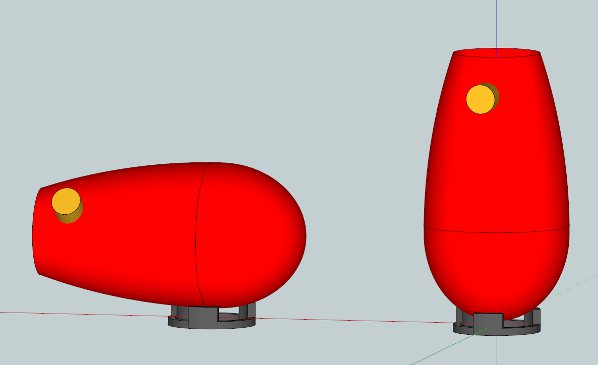
This ovoid design is shaped in a complex elegant manner, inspired by Nature. Though difficult to track and slew, I find this design compelling. I wonder if it will ever be built.
The Sketchups can be found here:
ball scopes
elliptical bearings
eggscope
Pierre Desvaux from France has designed an elegant egg shape with beautiful symmetry. See http://dobsonfactory.blogspot.fr/2013/01/ze-egg.html
Both the trimmed ballscope and egg shape are two interesting approaches for overcoming the aperture limitation with the standard ballscope design.
Tom Conlin's SudiBall designs http://ix.cs.uoregon.edu/~tomc/Hobbies/Astronomy/ATM/SudiBall.pdf
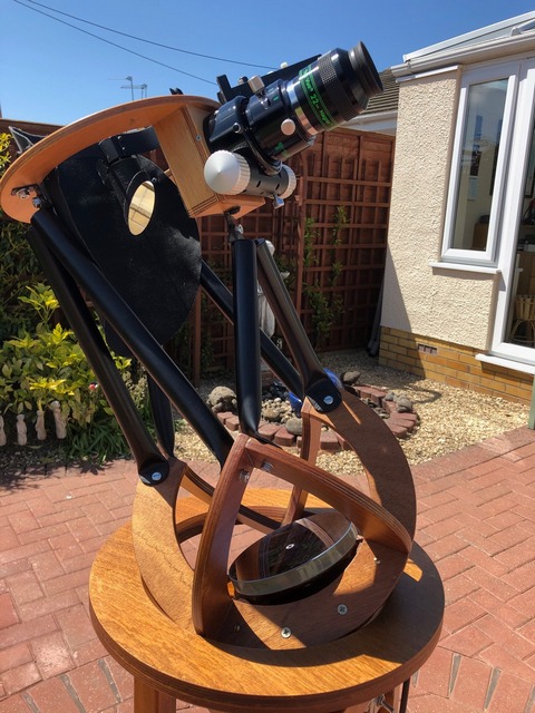
Chuck Lott's CloverBall
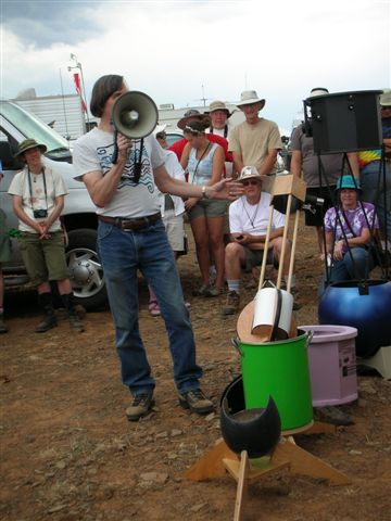
Porter ballscope replica by Dave Trott
Thanks to Jerry Oltion, Tom Conlin, Chuck Lott, David Davis and others for their thoughts and inspiration.
Winter 1976
A freezing howling winter night found a friend and I high in the remote Oregon mountains. My 10 inch F5 mirror having frozen over, I took out my Astroscan, while my friend busied himself calling for the spirit of the mountain, Bigfoot, to come observe with us, a brief discussion of Sasquatch dialect having ensured immediately prior. I was speechless: breathtaking wide field views of countless stars and nebulosity in Orion so bright that I winced. That little ballscope was a joy to use, though not the best fit in my backpack, banging into my back as I trudged up the trail. Alas, Bigfoot never showed.
Summer 2024
The 6 inch F2.8 and pan mount on the equatorial tracking base.
![]()
A simple to make pan that acts as a smaller portion of a ballscope, enabling 3 axis motion and sidereal tracking with a constant speed motor. The 'cutaway ballscope' works because the eyepiece is positioned slightly upward, never upside down.
Besides this webpage, check out my presentation at the Altaz 2024 conference. I describe the pan mount at the end of my one hour talk.
Weight, size and complexity in constructing the ball for large telescopes. Oltion's rule is the ball diameter is 1.5x the mirror diameter. A ball for my for 30 inch F2.7 therefore would be nearly 4 feet in diameter with a surface area of about 50 ft^2. The weight of 1/4" fiberglass is 2.6 lbs/ft^2 so total weight is 130 pounds. Add in the mirror and cell and trusses and upper end that weigh 100 pounds. That's a total weight of 230 pounds. Compare this to the current 100 lb weight of the 3-axis 30 inch F2.7. In any event, I do not need all of that nice, smooth and round ball to position the scope and to track the stars because the the eyepiece must point sideways for comfortable access.
A spherical segment can be cut from a large ball. The spherical segment is treated the same as the pan mount with wooden circles for reinforment. The weight of a spherical segment is less than the full ball.
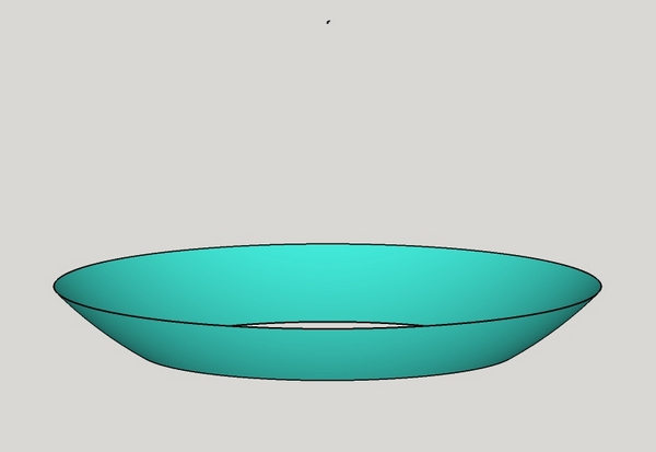
I was inspired by a small group of inventors playing around with and building ballscopes, specifically Jerry Oltion's Trackball which I have used myself and Pierre Lemay's asymmetric ballscope with dual tracking wheels. I was also inspired by equatorial tables and an article by Richard Berry explaining how the tracking platform evolves from horseshoe to split ring to cutdown split ring with limited tracking.
Other ballscope variations.
These were essentially designed to avoid the trouble, expense and weight of a full ball.
Commercial ballscopes: Astroscan, PortaBall. And of course the original ball mounted scope is by Isaac Newton.
Tracking inspiration came from Jerry Oltion, Pierre Lemay, Alphonse Pouplier and Norm James.
I studied removing sections of a ballscope like this.
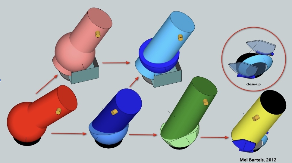
I cut out a paper model to verify smooth motion and sidereal tracking. I then purchased an inexpensive squirrel baffle made from sheet metal at a hardware store.
The pan mount can also be generated by considering an equatorial tracking table. Take the slightly curved tracking pieces and straighten them. This will create a slight tracking error of approximately 1%. Then 'spin' the straightened tracking pieces about the azimuth axis forming a pan. In effect, this gives the tracking platform a built-in azimuth axis as well as a limited alt2 axis.
How to cut the pan is easily calculated.
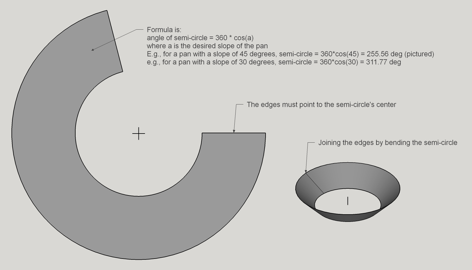
An hour of tracking time equals 15 degrees of rotation. At 45 degrees latitude this is a vertical travel of 10 degrees. Therefore the pan's side should be at least 10 degrees. Mix in a few degrees for limited altitude2 movement. The pan's depth on the 6 inch F2.8 is 25 degrees. My 3-axis double flex rockers on my 16 inch and 30 inch scopes have 15 degrees of altitude2 travel.
Details of the two wood rings that I cut out and fiberglassed to the squirrel baffle.
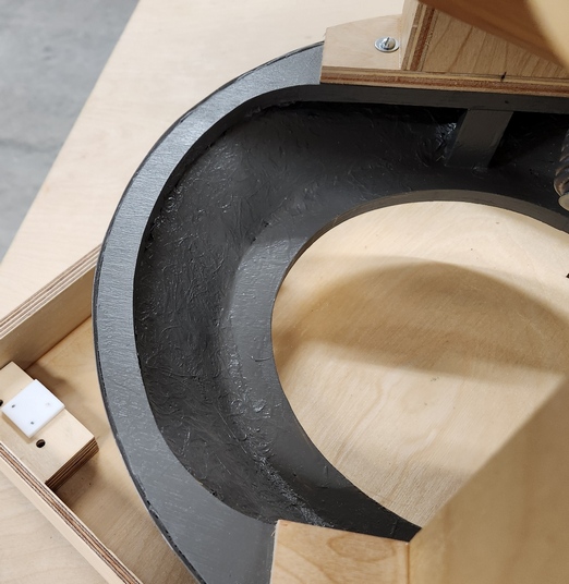
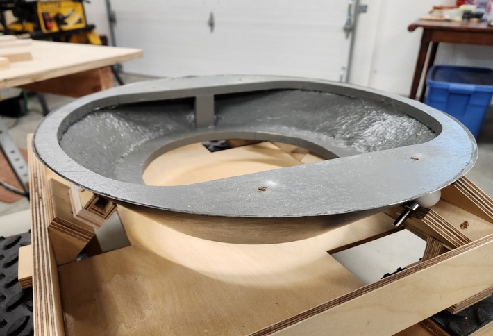
The pan moves easily in a plastic bucket and demonstrates that it is essentially spherical.
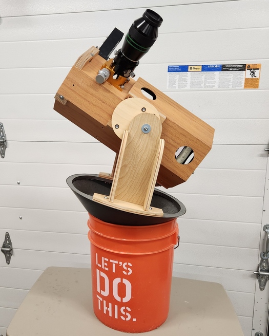
Driving the pan is similar to driving a ballscope, per Jerry Oltion and Pierre Lemay. I estimate a +-1% tracking error because of the flat pan instead of a rounded ball segment. Note that the Oltion and Lemay ballscopes are driven by a cylinder. Since my pan is 'flat', ie, is made from a flat piece of sheet metal, a ball must be used to drive.
The ball that the pan emulates has a perimeter of 60 inches. Swiveling the pan back and forth, I measure 6 inches of tracking travel, so that is 2.4 hours of tracking time. Here's the tracking base that I built. Note that the pan is stopped by the interior flat piece of wood, keeping the pan from falling off.
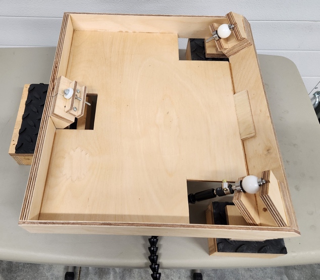
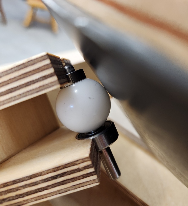
It works - the tracking motions are as hoped! The test is to aim the scope at the pole, then see if the tube only rotates on its axis. Here I spin one Nylon drive ball with an extension attached to the ball's shaft video 1, Here is another video where I push the pan, allowing it to follow the balls' natural equatorial motion video 2.
Next I tried the pan mount under the stars. Aiming and centering Regulus (my old equatorial alignment instincts kicked-in, including remembering which side of Polaris to point at). I let the star drift to the edge of the field, then turned the flexible drive shaft which is attached to the Nylon drive ball. The other Nylon ball turns freely, helping to steer the pan. The star returned to the exact center of the field! I repeated this several times, each time Regulus re-centered perfectly. Success!
For driving the pan at a different angle than the latitude, see my omni-latitude equatorial tables discussion.
Many modern equatorial tables are can be re-imagined as vertically oriented pan mounts driven by rollers. For more, check out Reiner Vogel's equatorial platform discussion and my omni latitude drive platform.
The pan mount needs to be balanced in all three dimensions. I need to balance:
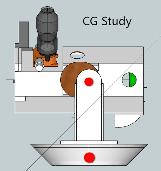
The altitude brake is two Teflon pads pressed against each other. Wonderfully smooth and able to handle the unbalance caused by a heavy eyepiece and coma corrector. This idea comes from a large equatorial mounting in a Sky and Telescope magazine article from September 1959, page 643-, by Walter Seerau. The scope featured a polar axis of two large machined metal discs with a thin Teflon sheet between for slewing. When let go the mount would resume tracking. As a result of that article, older ideas such as thin leather were successfully tried.
An equatorially mounted telescope has it easy. The telescope can track the stars with a simple slow constant rotation about the polar axis. This is called 'equatorial tracking'. An altazimuth mount rooted firmly on the ground is simpler and surer but cannot easily track - after all there's no polar axis. Instead tracking is a complicated affair of ever varying drive rates in both altitude and azimuth.
The Earl of Crawford devised a clever way so that an altazimuth telescope can simulate equatorial tracking. A cord is attached from a point on the polar axis to the end of the telescope's tube. The telescope tube is weighted in the rear to keep the cord tight. As the telescope swings across the sky constrained by the cord, it describes an equatorial tracking arc.
Here we see an altazimuth mounted telescope with the Earl of Crawford's tracking cord attached. The telescope is pointing at the celestial meridian (aimed southward, if in the northern hemisphere, aimed northward if in the southern hemisphere). The bottom of the tracking cord is attached to a point along the polar axis. Because the polar axis makes an angle of 45 degrees with respect to the horizon, the scope must be situated at a latitude of 45 degrees on Earth.
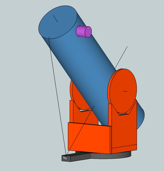
Now let's swing the telescope across the sky, keeping the cord tight. The telescope will simulate an equatorial tracking arc across the sky.
Ideally, the cord is attached to a point on the telescope's optical axis since it is this optical axis that ought to track equatorially. Attaching to the side of the tube causes tracking errors. That's because the optical axis is not coincident to the axis defined by the arm's attachment point to the telescope tube and the intersection of the three axes: the polar axis, the azimuth axis and the altitude axis.
The arc that the Crawford arm swings through is not the same arc that the telescope's optical axis swings through. The 'Crawford' arc can be calculated by lowering the telescope's altitude reading by the angle the attachment point to the telescope's tube makes with the intersection of the three axes.
The following graphic shows the telescope equatorially tracking perfectly for two hours. The arc shows the slow movement of the telescope's optical axis across the sky. Check out how the optical axis is perfectly aligned with the end of the tracking arc.
![]()
Now let's check out where the telescope is pointed after two hours of simulated equatorial tracking motion by the Earl of Crawford arm. You can see an error in the tracking motion. In this case it is a substantial six degrees. That means that an object will drift out of the field of view in 10-20 minutes.
![]()
You can see this for yourself by performing this simple experiment. Attach a small telescope to the side of a Dobsonian telescope at some crazy angle, so that it is not pointed in the same direction as the Dobsonian. Point the Dobsonian on a bright star and note the field in the small auxiliary telescope. Wait a dozen minutes and re-aim the Dobsonian. Inspect the field of view through the eyepiece of the auxiliary telescope; you'll see that the field has drifted. That's the Crawford arm tracking error.
In the case of a telescope pointed at the celestial meridian, the change in altitude is minimal. If the Crawford's arm tracking speed is adjusted, the tracking error can be significantly reduced. In the image above, the Crawford arm can be moved further along, reducing the error to about a degree.
The Crawford arm was used on Lord Rosse's 72 inch Leviathan, perhaps taking advantage of the minimal altitude change.
This is why a Crawford arm for an equatorial table will only work when the arm is tied to the telescope's optical axis.
What to do? The essential problem is field rotation: the tube does not rotate to match the sky's twisting motion. If the tube cannot rotate, then perhaps the arm can.
If the arm is attached to a slippery rotating ring and pulled tight, then perfect tracking is restored.
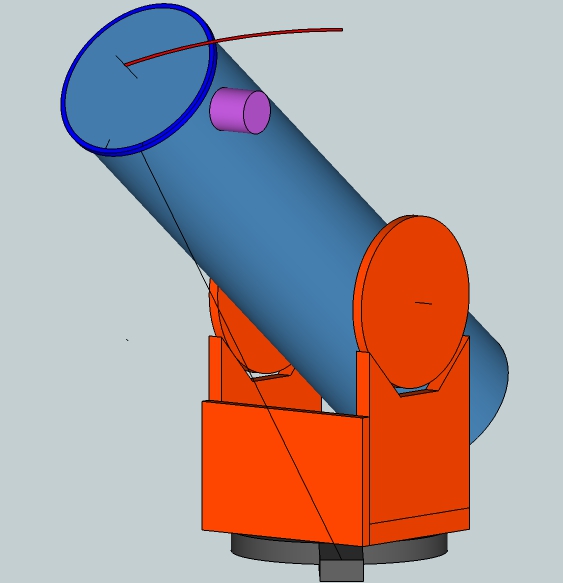
Another answer is to elevate the tube such that a line parallel to the rod's attachment point to the telescope tube goes through the center of rotation of both the azimuth and altitude axes. The tube's off-center location will cause it to pull against the rod as it is swung upward.
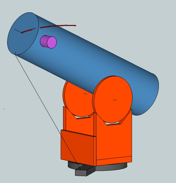
Yet another answer is to attach the arm to the optical axis that emerges from the back of the telescope tube. By adding a Declination clamp, we venture into the territory of the Morse Transformer, a wonderful analog equatorial to altazimuth calculator invented in the 1930's.
As I showed with the Morse Transformer, another possibility is to clone the telescope's altazimuth axes, moving them to the side of the telescope. Then a Crawford arm can be attached directly to the cloned optical axis that intersects the cloned polar axis. You can see that the tracking mechanism moves with the rocker box but the polar axis that intersects altitude axis and the cloned azimuth axis stays aligned with the sky.
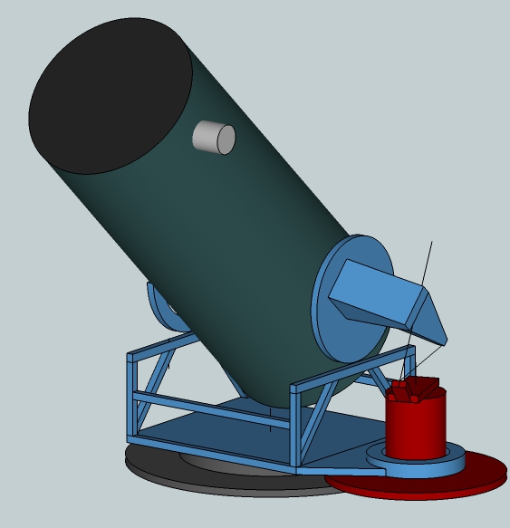
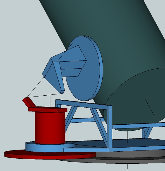
Google Sketchups:
the Earl of Crawford arm study
the Morse Equatorial Transformer
I've developed a 3-axis mount using a double flex rocker that I find quite superior. Near the horizon we desire altitude and azimuth motions, a natural swinging up and down along with pushing around in a circle. However, more overhead, we desire an altitude-altitude motion, where the scope moves up and down as before but also towards us and away from us with no horizontal swinging. By setting the friction of movement properly, we can automagically slide between alt-az motion and alt-alt motion as the tube moves up and down. I've build three scopes with this motion: a 25 inch [64cm], a 30 inch [76cm] and a 16.25 inch [41cm].
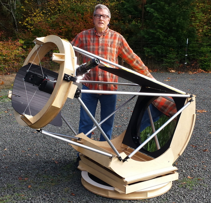
I mean, geez, now you have three drives and three motors and they will have to be under computer control to boot. The attractiveness is that three axis mounts have no field rotation, and can be aimed so that only a single axis need be moved to track satellites. In addition, three axis platforms free the builder from the constraint of building the latitude into the platform. Really, it's fun to investigate and design three axis mounts since the additional third axis opens up design possibilities, particularly if slewing is restricted to two axes and the third axis is of limited travel and only turned on to freeze field rotation during tracking. Time will tell whether the pluses will outweigh the additional complexity of three motors.
Here's some numbers showing three axis tracking with no field rotation for an alt-alt-az mount located at north 44 degrees latitude with the starting third axis azimuth aimed below the pole, locked on object rising in the east. These are distances moved in each axis over one minute intervals. Specifically,
Altitude = 50 deg
Azimuth = 90 deg
Field rotation angle = 38.471
Tracking rates:
Rotation about sky's zenith = 0.173 deg
Primary altalt axis aimed at horiz = 0.254
Right angle to primary altalt axis = 0.164
The three motors are all moving at a rate with a magnitude of 1/7 to 1/4 degree per minute, which is analogous to the sidereal tracking rate, a very reasonable and easy rate of motion to achieve.
A 48 inch three axis scope has been located in Cloudcroft New Mexico for years. See Manly's Unusual Telescopes, page 88, and his discussion of three and four axis mounts on pages 84-91.
A computer controlled drive system is not a forgone conclusion. Decades ago before digital computers, some amateurs used a mechanism called an equatorial transformer that took mechanical action generated by a small equatorially aligned machine and forced the 2-3-4 axis mount into following its motion.
Richard Berry has suggested a table mount with three motorized pistons. Also see my articles on turret equatorial tables and tilted equatorial tables.
Here are some of my back of the envelope (what's the appropriate nickname when using a CAD program?) sketches:
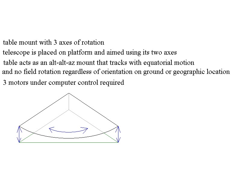
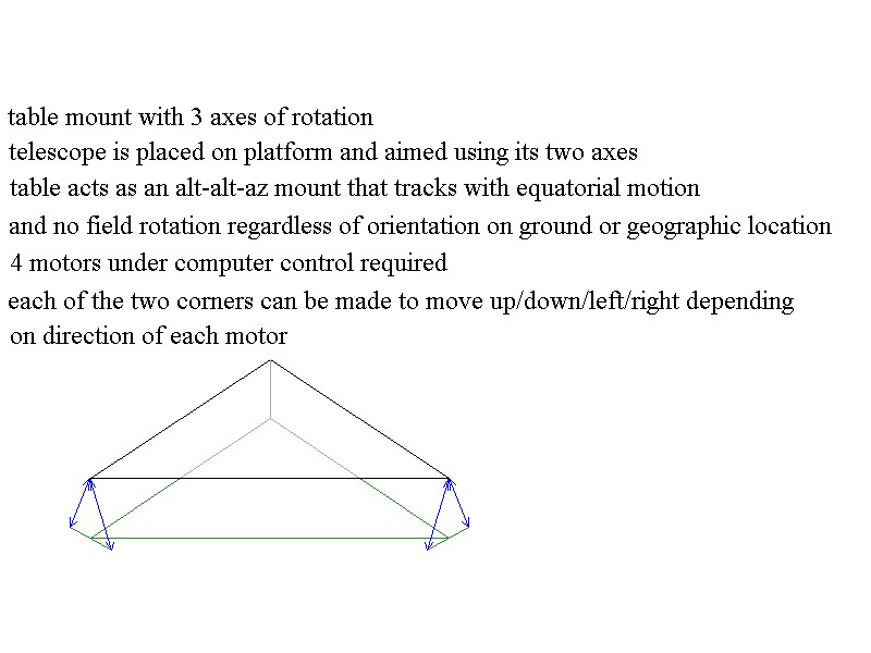
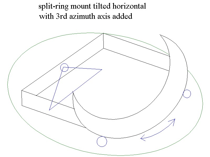
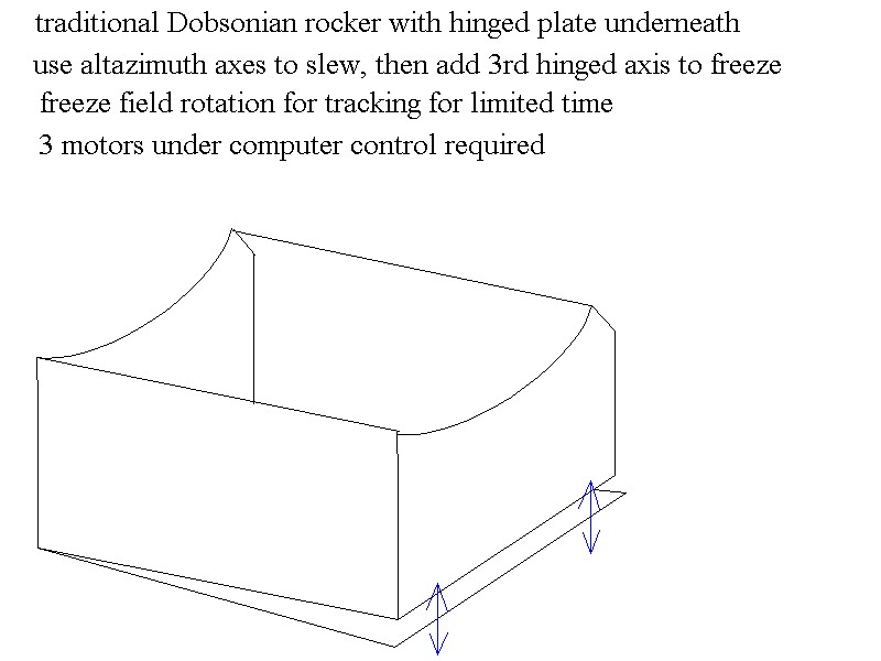
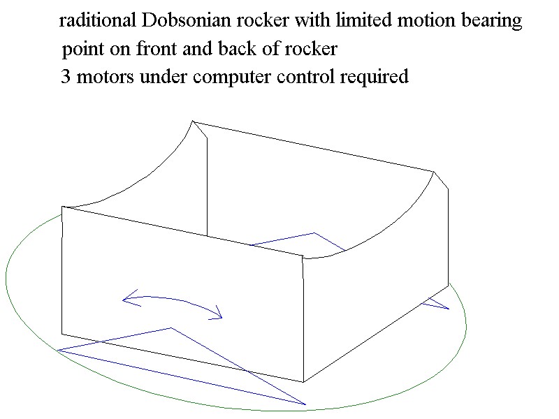
[Mel Bartels' introductory comments] The Holcomb mount stands as a remarkable achievement in design, anticipating modern design principles a century earlier. Holcomb's mount is simple, sturdy, with unexpectedly large aperture for its era. He eschewed tracking for the compelling task of visually revealing the heavens. There are remarkable similarities to John Dobson's design that came more than a century later. Holcomb also began this country's first telescope making company at a time when it was thought that Americans were not up to the task. When Alvan Clark began his groundbreaking optics work, he visited Holcomb and purchased glass from him. Holcomb's mount lives on today in the guise of F.J.Seller's mount. America's oldest surviving observatory began with a Holcomb telescope, eventually to be replaced with a Clark refractor decades later, the task of re-polishing and figuring the speculum mirror proving too burdensome. A great image is at http://learninglab.si.edu/q/r/12225
The stand for the reflecting telescope invented by Mr. Holcomb is undoubtedly the most economical and efficient ever made. Below is the general appearance of the telescope and stand.
The lower end of the telescope, where the speculum is located at 'a', rests upon the ground; the upper end, which is somewhat larger, in order that the head my not obstruct the light, when the eye is applied at 'b', is supported by two sliding legs 'c', and 'd', which are lengthened or shortened by means of the thumb-pins 'e', 'f', shown more plainly in fig.2; a catgut cord passes from the thumb-pins down the front of the upper sliding rod, over a small pulley at 'g' and 'h', thence along a groove cut in the front surface of the lower sliding rod up to nearly its top at 'c' and 'd', where it is fastened; an iron hand attached to the top of the lower rod, and another attached to the bottom of the upper rod, holds the whole firmly, yet allows a free movement when they are made to slide upon each other by winding or unwinding the cat-gut cord upon the barrel of the thumb-pins 'e' and 'f'. The lower ends of the sliding rods are pointed and armed with iron, and at the lower end of the upper part of the sliding rods, camping screws are placed, just below the pulleys in order that the whole may be securely fastened while being transported from place to place. The method of attachment to the upper end of the tube is shown in fig. 2, a brass saddle 'i', is bolted to the tube, between the ears of which the parallel plates of brass 'k', 'l', move freely upon the pin 'm' 'n', between these plates of brass, the sliding legs are placed, and turn upon the two pins 'o', 'p'. It will be perceived, that by extending the sliding legs at the bottom, or by lengthening or shortening them, almost any required altitude may be given to the telescope, and to keep the thumb-pins 'e' and 'r', from unwinding with the weight of the telescope, two pieces of hard wood 'r', and 's', are located below them, having a steadying pin at the bottom and a clamping screw at the top as shown in fig. 2, by turning this clamping screw the smooth flange of the thumb-pins is pinched between the rod and bit of wood, and thus any requisite amount of friction is obtained. The eye-piece is located at 'b', fig. 1, and screws or slips into a ring attached to a bar, which is racked, and the proper position for distinct vision is obtained by means of the milled head. The finder 'u' is a small telescope mounted upon two pins, which pass through elongated holes in the tube, and by means of nuts which screw upon the pins outside and inside of the tube, is held firmly, and adjusted, so that when any object is brought upon the intersection of the hairs in the focus of the eye-piece, it will be in the field of view in the telescope. The stand I have now described is remarkably steady, since the speculum, which forms the image, rests upon the ground.
from:
Annals of Science, Volume 1, page 141 (April 15, 1853),
found in 23 libraries in the USA,
being a record of inventions and improvements in applied science,
Publication: Cleveland, Printed by Harris and Fairbanks.
Vol. 1 'including the transactions of the American association for the advancement of science.' Ceased with 1854
Vol. 2, 'including the transactions of the Cleveland academy of natural sciences.', American association for the advancement of science, Cleveland academy of natural science.
Responsibility: Conducted by Hamilton L. Smith.
scanned by Matt Considine, transcribed by Mel Bartels.
Also see Sky and Telescope magazine, August 1978, page 158
A recent Holcomb, nicely done is at http://www.cloudynights.com/topic/491231-a-long-focus-newt-on-a-holcomb-mounting/
For more on the remarkable Holcomb, the first American manufacturer of telescopes, see http://en.wikipedia.org/wiki/Amasa_Holcomb and http://www.europa.com/~telscope/holcomb.txt
For more on F.J.Seller's mount and modern variations, see August 1976 Sky and Telescope, pages 138-140.

And see Craig Daniel's Dogson Telescope
Morse's mount deserves wider attention. Here is a representation of his design as described in Scientific American, June, 1942, Ingalls and pictured in Henry Paul's, 'Telescopes for Skygazing'.
A curved arc in the shape of a sickle attached to a tracking cylinder tracks the telescope's tube across the sky in an equatorial arc. The rear of the telescope's tube is clamped to the sickle by a trolley at the desired Declination. The telescope's tube pulls the altazimuth frame along with itself. The tracking cylinder is polar aligned with the polar axis cutting through the telescope tube's center of gravity. The tracking cylinder only spins: since it is attached to the ground board it stays motionless while the rocker box rotates around it.
Long before there were computerized altazimuth drive systems for telescope mounts, the Morse mount mechanically translated equatorial motion to altazimuth motion.
As explained in the Scientific American article, the idea originated with A.B. Hendricks Jr of Pittsfield, Mass in 1936. Hendricks' idea was to link equatorial motion to an altazimuth mount. Upon seeing this in 1936, H.F. Morse of Southport, Connecticut devised an entirely different approach to the mechanical transformer.
He wrote that, 'The object was to avoid certain inherent shortcoming in large equatorial mountings. Estimates indicate a much lower cost. Materials could be better used-with lessened total weight. Because there would be no transfer of weight from one bearing to another, there would be no distortion of parts. Because of the ease and flexibility of the adjustments, less precision work would be required on various details. Astronomers would work in an always level position and in a constant temperature room at either end of the horizontal axis, where light could be directed with three reflections. Because the tube moves about the horizontal axis in one plane alone, the tube could be made very rigid and at the same time relatively light. The whole instrument could be floated in an annular tank of mercury, thus leaving only enough weight on the annular track (precision ground) to ensure accurate rotation around the vertical axis.'
A curved blade representing the Declination angle is attached to the polar axis drive which represents the hour angle. The telescope's axis below the tube is tied to the curved blade. The altazimuth axes intersect the polar axis. An equatorial tracking movement translates into altazimuth motions.
The Sketchup model can be found at https://3dwarehouse.sketchup.com/model/53af76a186e18e456ed97933d0fe8bb5/The-Morse-Equatorial-to-Altazimuth-Transformer-Telescope-Mount
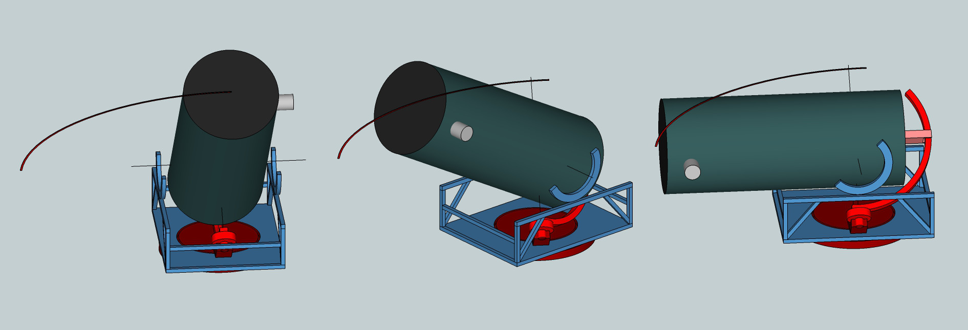
And we can extend the Morse transformer to eliminate field rotation by using a three axis mount like this, showing one hour tracking. Note how the eyepiece angle is lifted up to follow the equatorial tracking arc as opposed to above where the eyepiece angle stays horizontal.
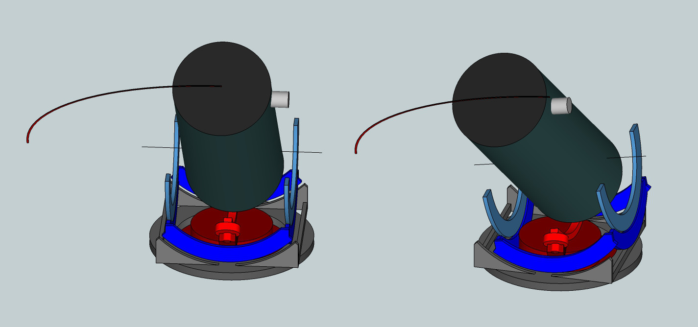
The Great Paris Exhibition Telescope of 1900 also used an equatorial to altazimuth transformer called a Foucault Siderostat. See Wikipedia's https://en.wikipedia.org/wiki/Great_Paris_Exhibition_Telescope_of_1900#/media/File:Great_Ex_Telescope_Design.jpg,
and Journal of the British Astronomical Association, Vol. 95, NO.3/APR, P. 89, 1985 http://adsabs.harvard.edu/full/1985JBAA...95...89M.
Conceptually linked is the Earl of Crawford's tracking arm. The length of arm represents the Declination with the arm tying the polar axis to the tube's axis, resulting in an identical equatorial to altazimuth transformation.
Both equatorial axes and both altazimuth axes intersecting is an optimized design. I strongly suspect that the designers started with less optimal designs where the equatorial portion of the transformer was below or at the side of the altazimuth portion. This takes us back into the rich sophisticated world of analog devices and mechanical linkages. It also gives the modern day amateur new design possibilities.
After some thought, mental gymnastics and immersing myself in the mechanical analog world of linkages I devised an equatorial to altazimuth transformer where the equatorial portion is placed at the side of the altazimuth mount. Two disks, one under the altazimuth mount and the other at the bottom of the equatorial section, rotate against each other such that the equatorial portion maintains its polar alignment. The altitude arm is coupled to the curved Declination arm. Just as in the Morse transformer proper, all four axes intersect at one point to the side of the rocker: altitude, azimuth, polar equatorial and Declination. Here I've scaled the polar portion smaller, albeit increasing leverage.
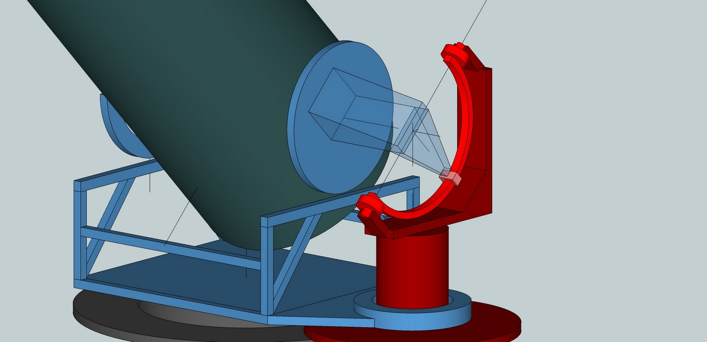
As the equatorial portion tracks, it forces the altazimuth portion to track also. Interestingly, the equatorial portion could be set free to move as needed as the scope is aimed about the sky. This causes the equatorial portion to act as setting circles. In fact, the field rotation angle can be read too.
Here is the change in position after one hour of equatorial tracking. The equatorial portion maintains its polar alignment while the altazimuth portion is forced into tracking an equatorial tracking arc across the sky. This could be extended to a three axis mount if the Declination car is coupled tightly to the altitude extension.
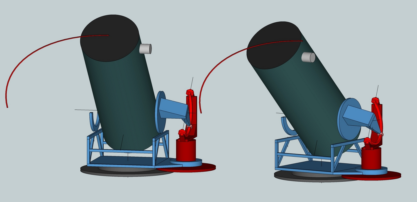
Here's the arc extended into an armillary sphere. Note that the telescope's pointing position has changed: the hour angle is increased, the Declination lowered, the altitude lowered and the azimuth increased.
| Altitude movement... | |
| Altitude bearing separation (deg) = | |
| Altitude bearing materials | |
| Azimuth movement... | |
| Azimuth bearing materials | |
| Rocker... | |
| use auto-calculated weight | |
| Adjust scaling |
| Results: |
An essential feature of John Dobson's telescope design is that the telescope moves smoothly and precisely about the sky, staying put once the operator lets go. There is no clamping or locking down. Tracking an object across the sky consists of periodic adjustments by pushing the scope very small distances while looking through the eyepiece. His design depends on an interesting property of Teflon on pebbly Formica, namely that the friction felt when moving the scope is about the same as the friction felt while starting the move. In other words, the dynamic friction equals static friction. Most materials stick worse than they move, leading to jerky motions.
The force to move the telescope should not be so great as to demand a great deal of effort, particularly when making very tiny high magnification adjustments by hand, nor should the force be so slight that wind can move the telescope. Ideally the force in both azimuth and altitude axes is roughly the same so that the axes 'disappear' as the scope is moved to and fro.
The force to move the scope in azimuth increases as the scope is pointed upward. I set the angle at 48 degrees or halfway up the sky. This is the optimum pointing angle given the range of altitude movement, area of sky and seeing conditions. Keep in mind that as the scope is pointed further upward that the azimuth resistance to movement becomes quite stiff.
I like a frictional force of two to three pounds (1 to 1.5 kilos); others prefer less friction. This gives me a smooth and not-too-stiff touch at the upper end of the scope, avoids balancing issues with heavy eyepieces and resists weathervaning from wind gusts.
The altitude friction can be adjusted by varying the bearing angle and the altitude bearing radius. The azimuth friction can be adjusted by varying the distance from the pads to the pivot (the azimuth bearing radius) and by changing the material pairing. Bearings can be substituted for one or more of the bearing points with a proportionate reduction in friction. For instance, the azimuth friction can be reduced by two-thirds if two of the three bearing pads are replaced with roller bearings. More unusual is to build a trolley with a pad on one end and a roller bearing on the other end. By moving the pivot location closer to the pad the friction can be increased and by moving the pivot location closer to the bearing the friction can be decreased.
The formula and concept is from Richard Berry's article in Telescope Making 8, page 36-.
The size of the pads modestly affects the quality of motion. It's a long standing rule of thumb that 15 PSI (pounds per square inch) is ideal.
The key here is to have a favorable static to dynamic friction ratio where the friction to begin the movement is less than the friction to continue the movement. This feels like 'butter' at the eyepiece.
| Altitude bearing separation (deg) = | |
| Altitude bearing materials | |
| Azimuth bearing materials | |
| Rocker... | |
| use auto-calculated weight | |
| Adjust scaling |
| Results: |
Imagine the altitude bearing getting bigger and bigger. The rocker's weight shrinks, which is good but so does the height, lessening its rigidity, which is bad. But what if the altitude bearing points are placed at the rocker's corners and under each corner an azimuth bearing is placed resulting in four azimuth bearings that ride on a rigid ring? In fact, the altitude and azimuth bearings can be combined into a single block or post with the rocker reduced to merely holding the bearing blocks in relative position. The flex rocker strips away unnecessary weight and structure. We can have our ultralight rocker with good rigidity. Additionally, the mirror box can swing down through the base to lower eyepiece height when pointing near the zenith.
Here is a Google Sketchup of my ZipDobII, Joe Rotman's 16 inch [41cm] UltraLight, Greg Babcock's circular flex rocker 24 inch [61cm] ultralight and my 3 axis double flexing rocker on my 25 inch [64cm].
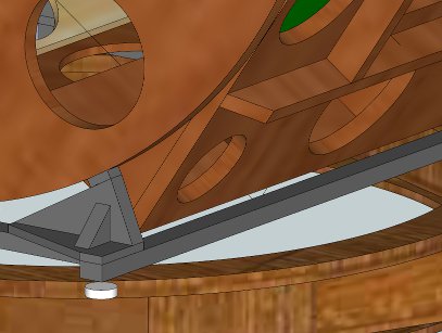
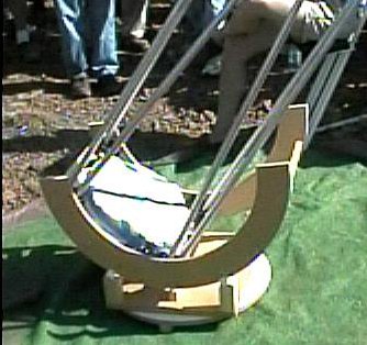
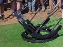
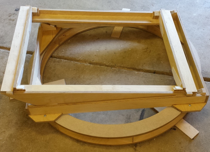
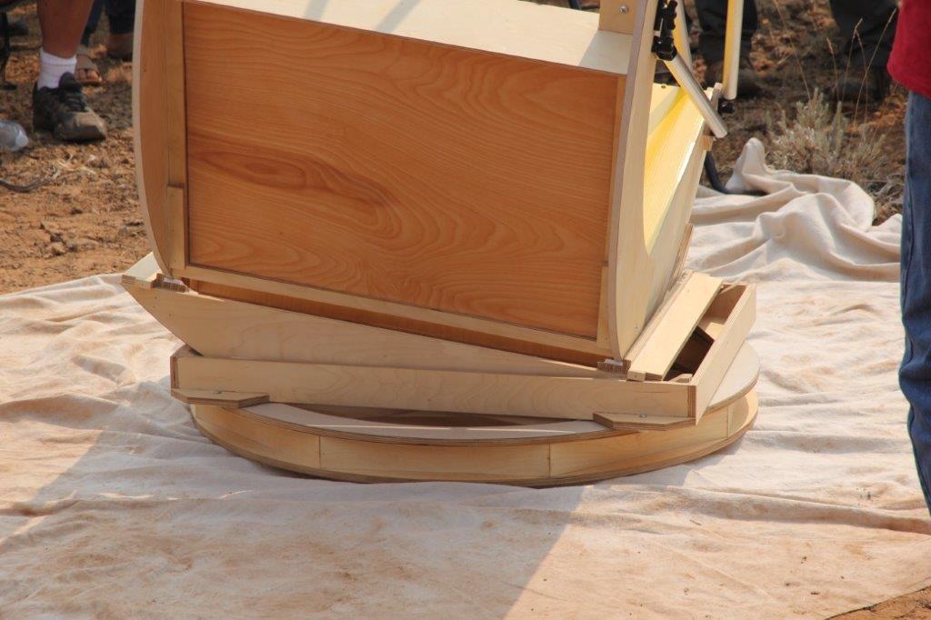
The bending force on a post due to pushing the scope is:
Bending force = push needed to break static friction * altitude bearing radius / ratio of upper end to center of mass / 4
For example:
Bending force = 1.5 lbs * 23 / 12 / 4 = 0.7 lbs
These forces are very small, which is why thin spacer rods between posts are sufficient.
In order to keep the post height to a minimum, it is common for the azimuth bearings to sit on a rigid center-less base ring. This allows the mirror box to swing through the base. The eyepiece height above the ground when the scope is pointing upward is minimized when the mirror box sits inside the base ring just above the ground.
| Latitude (deg) = | |
| Tracking time (minutes) = | |
| Adjust scaling |
| Results: |
The polar axis must pass through the combined center of gravity of the tube assembly, rocker and the equatorial table's platform.
Values for a four corner equatorial table are calculated where a tracking arc is situated at each corner of the equatorial table.
Other table designs include three arcs (two on the north side of the platform, one on the south side), two arcs on the north side and a pivot on the south side, and finally, two pivots, one on the north side and one on the south side.
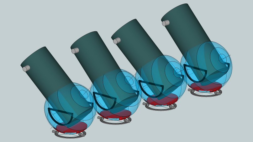
I've been fascinated by the equatorial table, or Poncet Platform, ever since it was invented in the late 1970's by Adrian Poncet. The platform's versatility has been proven by its use from small table top telescopes to giant telescopes - even an entire observatory building!
While the polar alignment has not proven too difficult, the equatorial table suffers from a serious limitation: it's built to a specific latitude. Traveling north or south a few hundred miles to a major star party means uncomfortably tipping the platform up on edge. Is there anything that can be done about this limitation?
Jerry Oltion's Trackball cleverly uses a single roller aligned parallel to the polar axis pressed against the bottom of the ballscope. A single tracking roller that is slid along a curved holder based on the site's latitude
http://www.sff.net/people/j.oltion/trackball.htm
Jerry's mounting design could be trimmed down into a hemisphere, resulting in an equatorial table platform. For moderate latitudes the drive arm rises above the two rollers.
My idea is that the curved pads cut out from a hemisphere can be driven by two rollers working on two lines of latitude; each wheel rotates at its own unique constant rate. The drives rates depend on the site's latitude. Changing latitude is a matter of resetting the wheels' drive rates.
For example, let's say that the drive wheels' diameter is 1.5 inches [4cm] and that the virtual ball's diameter is 20 inches [51cm]. For the placement of the drive wheels and pads shown the drive rates for a site of 45 degrees latitude are:
pole facing motor: 20 inches / 1.5 inches * sin(line of latitude of 75 deg) * 1.002737909 sidereal rate / 1440 minutes per day = 0.0090 rpm
side facing motor: 20 inches / 1.5 inches * sin(line of latitude of 35 deg) * 1.002737909 sidereal rate / 1440 minutes per day = 0.0053 rpm
and for a site of 30 degrees latitude are:
pole facing motor: 20 inches / 1.5 inches * sin(line of latitude of 90 deg) * 1.002737909 sidereal rate / 1440 minutes per day = 0.0093 rpm
side facing motor: 20 inches / 1.5 inches * sin(line of latitude of 45 deg) * 1.002737909 sidereal rate / 1440 minutes per day = 0.0066 rpm
Here you can see the concept. Note how the platforms for site latitude of 45 degrees and site latitude of 30 degrees are identical; the only difference being that the two drive motors operate at different rates causing the platform to track on different lines of latitude.
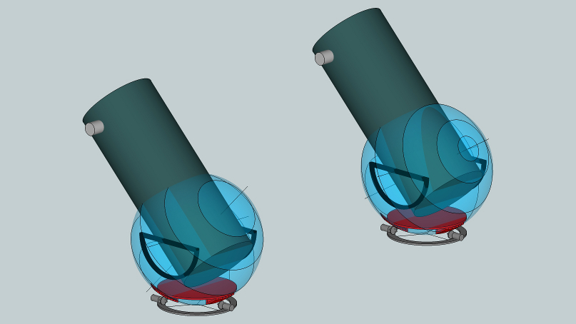
Here is what the platforms for latitudes of 45 and 30 degrees respectively look like at the end of an hour of tracking.
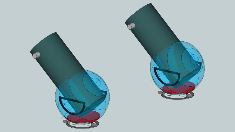
There is a slight difference in the platforms' ending angle. The platform on the left tracked for site latitude of 45 degrees, while the platform on the right tracked for a site latitude of 30 degrees.
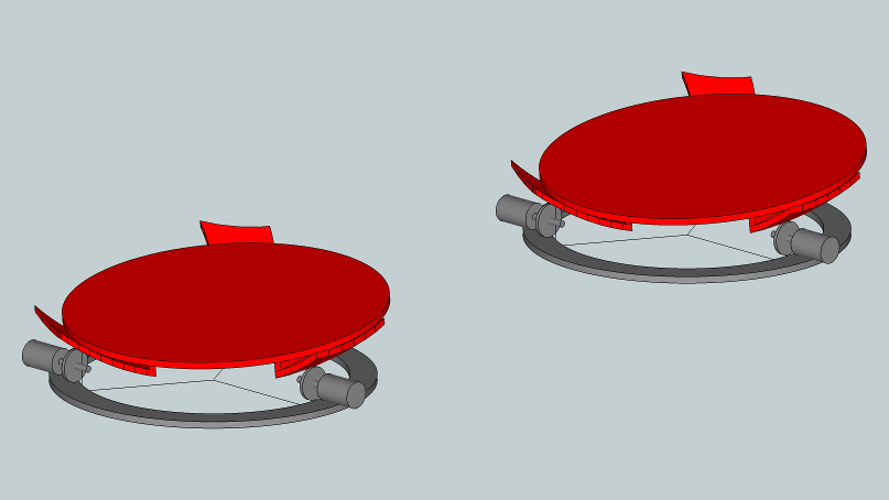
The drive wheels will need to be made from hard plastic, possibly with a thin ribber O-ring to generate friction. The friction is needed to resist sliding as the telescope sitting on the platform is pushed about the sky.
The trade off for the omni-latitude table is two fold:
1. Two motors that rotate at constant rates, the rates varying per the site's latitude
2. The need to grind or sand the curved pads in two dimensions; many equatorial tables have their curved tracking surfaces ground in one dimension, this has to be expanded to two dimensions.
Sketchup model can be found here
Other inspirations include Alphonse Pouplier's 'Robotic Astroscan' (see Sky and Telescope magazine, August 1993) where he uses two tracking wheels that sidereally track and provide goto motions for a ballscope. And Pierre Lemay's dual tracking roller platform places both rollers at the same line of latitude. Conceptually it appears more in line with Jerry's thinking than with the dual great circle tracker here. More can be found on Jerry Oltion's webpage noted above.
Mel Bartels, January 2013
Because the Earth rotates once every day, the stars at night appear to move across the sky in arcs. The telescope needs to follow the stars. We call this sidereal tracking or equatorial motion.
Equatorial mounts were invented to easily track the stars by rotating a polar axis at a slow constant rate (atmospheric refraction causes the tracking rate to slow ever so slightly near the horizons).
But the tipped polar axis in an equatorial mount adds bulk to the telescope and the popular German equatorial design requires counterweights, making transport and setup in the dark oftentimes a real chore.
Consequently much thought and innovation has gone into alternatives that imitate equatorial motion.
The altazimuth mount is often a more transportable and stable design but suffers from continuously varying tracking rates and field rotation at the eyepiece or camera. The Dobsonian, depending on your point of view, is either free from the complications that come with tracking devices, or is handicapped because the object drifts out of the field of view too quickly at higher magnifications.
A significant advance occurred in 1976 with the invention by Adrien Poncet of the tracking platform, originally called a Poncet Table, but now more often called an equatorial table. He reasoned that if the astronomer was willing to accept limiting sidereal tracking time to say an hour before having to start over, then a flat platform could be devised that imparts equatorial motion to any telescope placed on top. Subsequently the Poncet Table evolved into what we call equatorial platforms that better support heavy telescopes and track more accurately.
All tracking tables suffer from the restriction that they are custom built to specific latitudes. I've worked to overcome this restriction with my omni-latitude table. Continue reading...
Designers invariably think of equatorial tables in terms of limited equatorial motion. The English Yoke mounting becomes the Alan Gee design with a pivot point and cylindrical bearing sector. The Horseshoe equatorial mount (think Palomar 200 inch telescope) becomes the modern equatorial table with dual cylindrical bearing surfaces.
But can a table that imitates equatorial motion such that it supports a telescope aimed in any desired direction be built from different motions, different placement of axes? Let's investigate.
Can an equatorial platform be devised using the well understood altazimuth Dobsonian design where the primary axis, aimed straight upward, spins like a platter and the secondary axis pivots at right angles much like a crane going up and down? We should only need a snippet of limited motion in both directions, potentially an easy to build design. We know conceptually that a three axis mount can perfectly imitate sidereal tracking motion and that the three axes can be arbitrarily aimed anywhere and in any order of preference. Is there a solution where a limited tracking time and a vertically oriented axis can be found such that the third axis can be foregone such that motion in only two axes is necessary? It is said that constraints help problem solving. I'm about to find out if that is true here.
I'll use Sketchup, a free CAD program, to help picture the platform as it goes through its three dimensional motions. I'll snapshot the platform as it begins tracking, and then take a second snapshot after one hour of sidereal tracking motion. I'll then experiment with moving the snapshots around in order to find two axes of limited motion, one axis aimed upward and the other aimed sideways, just like a Dobsonian telescope.
Any flat table, as long as it pivots around the polar axis, will allow a telescope placed on top to be aimed anywhere in the sky and continue to track equatorially.
Here's the flat table oriented flat to the ground for a latitude of 45 degrees.
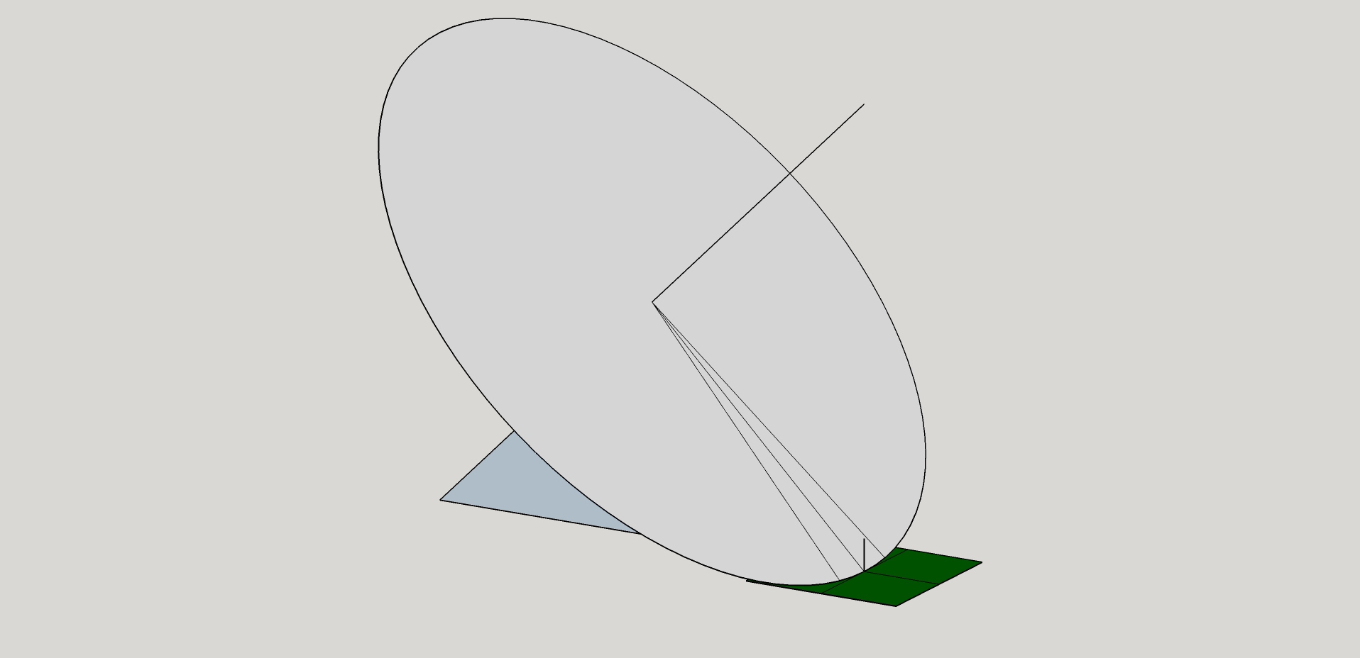
Now I'll rotate it through a half hour of sidereal tracking each way. The three snapshots like this.
![]()
As long as their orientation is not changed, we are free to reposition the tables as desired, so I'll place them so that there is a common point in their centers that represents a vertical axis of rotation. The tables intersect like this.
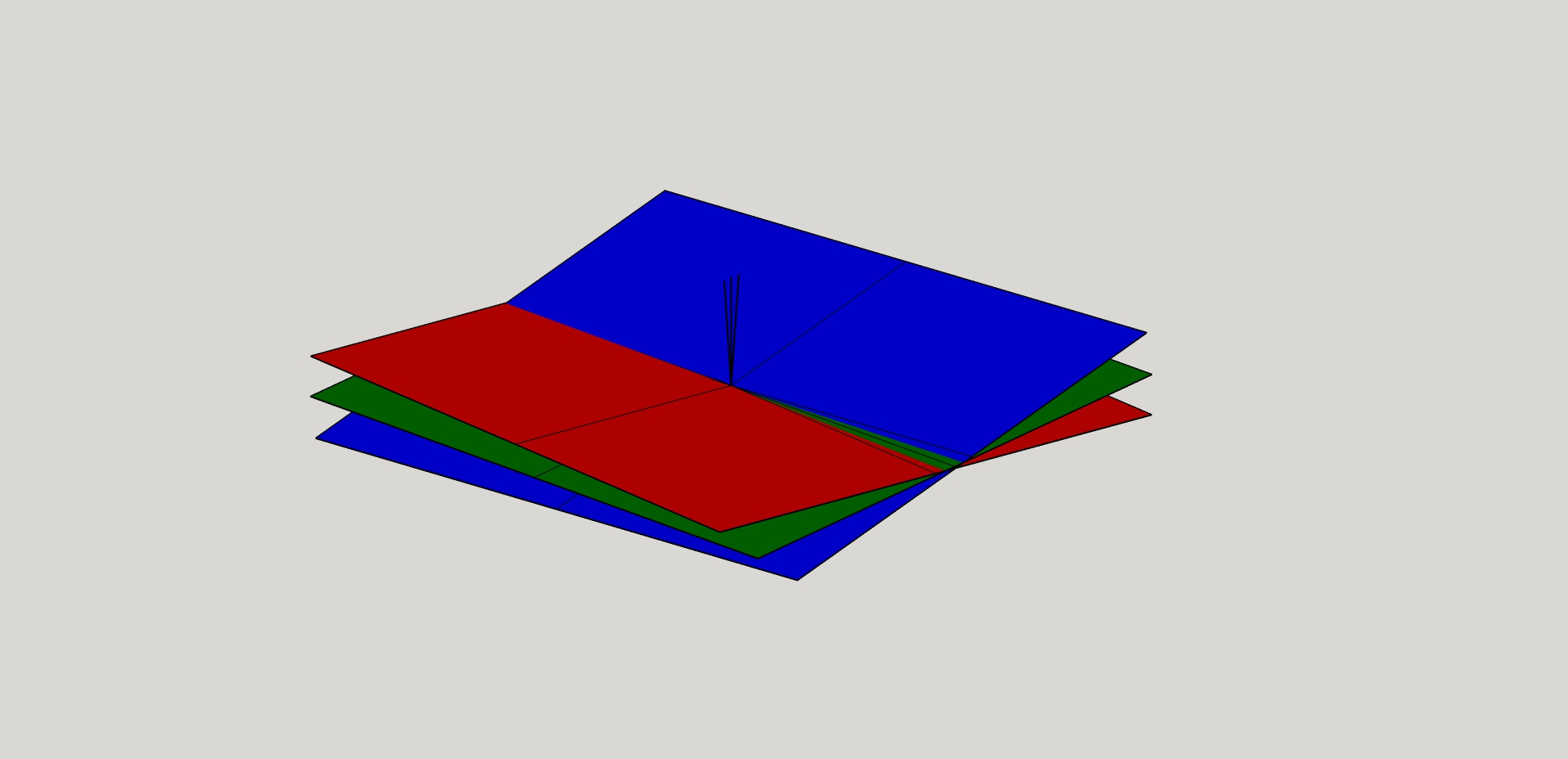
Here are the three tables from their south end: the first set the starting orientation, the second set a half hour into the tracking (the table is flat to the ground) and the final set an hour into the tracking, showing equal and opposite tip to the starting orientation.
![]()
The azimuth axis rotates +- 5 degrees as does the altitude axis. There is a slight tip to the azimuth axis of 0.6 degrees over the hour of tracking. That means a +- error in the eyepiece of 1/3 degree. For this to be an issue, the table will have to be polar aligned to 1/3 degree accuracy.
For latitudes closer to the pole the azimuth rotates more and the altitude rotates less; the reverse occurs for shallower latitudes.
For a half hour of tracking, these numbers are halved.
The driving rates should vary by +- 2% causing a fraction of a degree positional error, but can be ignored for visual high magnification use.
The pluses of this design is that simple Dobsonian styled bearings can be used. The disadvantage is that the scope will tip a bit off-balance. The top plate will need springs to counteract the tendency to tipping.
There are other placements of the axes that can be studied also, but they are similar in nature.
So there's the result of my design process. Onto other ideas, looking for constraints that lead to good solutions.
An equatorial table is a specially designed platform that allows any telescope sitting on it to follow the stars, just like a traditional equatorial mount.
The suggestion has been made over the years that tilting a table screws will also work. Richard Berry suggested this soon after the Poncet Platform was invented. There are two versions, the hexapod and the jack-screw.
We know that the hexapod works because the table can be made to rotate as well as tip in two axes, equivalent to a three axis mounting. Any three axis mount can simulate equatorial tracking motion with no field rotation. Jeff Kingsley proposed a hexapod mount for a radio telescope. A hexapod 1.5 meter (60 inch) Ritchey-Chretien was built in 1999 for the Bochum - UNC observatory in Chile.
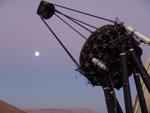
But what about a table that sits on three jack screws, not the six extending arms of a hexapod? The Oregon Scope Werks group decided to investigate this possibility. Here is my analysis and results.
Let's start by taking a platform and rotating it about a polar axis, aimed upward at 45 degrees (equivalent to an equatorial mount placed at a latitude of 45 degrees on Earth) simulating motion required for tracking. Jerry Oltion and I did this with cardboard and chopsticks (images by his wife, Kathy). (I recommend working through the problem with a buddy - the visualizations are non-trivial). The chopstick held in my hand (and hidden from the camera) on the right hand side in the images represent the polar axis. The chopstick that points out and away represents a telescope pointing south on the meridian. Jerry on the left is working to tilt a tracking platform to match the equatorial tracking table that I'm operating on the right.
The first image shows that the platforms are level with each other and that the telescopes on both platforms point to the same position in the sky. The second image shows one hour worth of tracking. Note that Jerry has had to tip his platform a fair amount so that both telescopes are pointed in the same direction. The final image shows the tilt table after two hours of tracking. Jerry has had to tip the platform a good deal to maintain the same telescope pointing angle.
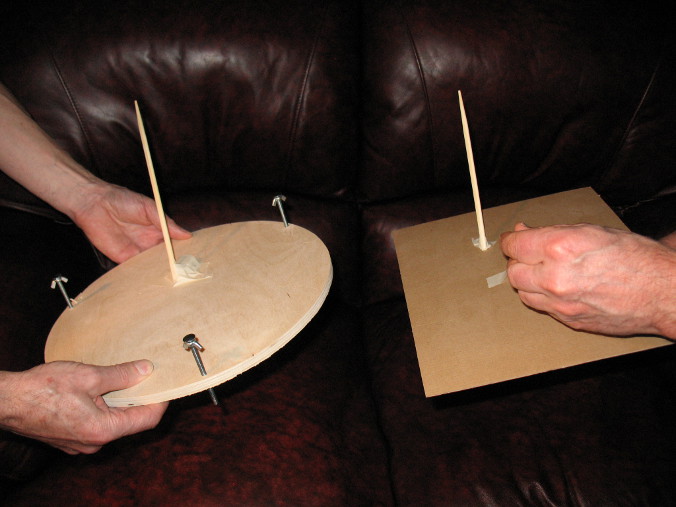
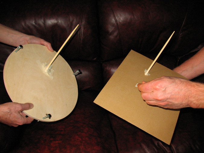
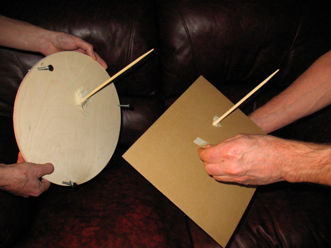
Let's also model this in Sketchup.
Here's an equatorial platform showing one hour tracking at latitude of 45 degrees. The scope is aimed to the south-east, about 25 degrees up and 25 degrees over.
![]()
Next let's align the platforms at a common point for convenience's sake and add three tip-tilt points underneath.
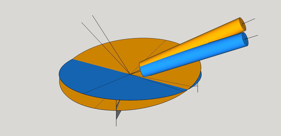
Now let's align the two telescopes to point in the same direction using only the three tilts afforded us. Oops, the lines pointing to the pole no longer are coincident. That means that the tilt movements must vary depending on telescope pointing angle at the start of tracking.
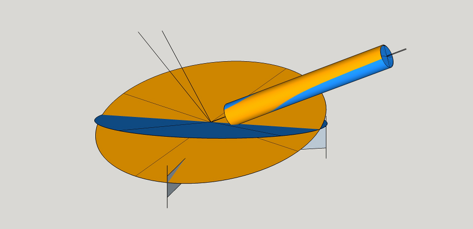
A closeup shows that significant field rotation (25.8 degrees) has occurred during the one hour of tracking.
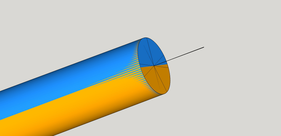
Let's see how much each tip point traversed for the one hour of tracking. The three tips changed 14.7 degrees, -3 degrees and -11.8 degrees.
![]()
Any platform that tips on an axis different than the polar axis and that cannot rotate will encounter field rotation, varying speeds of tilt and different amounts of needed tip depending on telescope pointing direction. Since the hexapod can rotate as well as tip, it can negate field rotation. Since field rotation is constrained, the initial telescope pointing direction no longer matters. The same changes in the hexapod leg lengths can be used over and over again, just like an equatorial table is reset to track again, regardless of initial telescope pointing angle.
Mel Bartels, January 2015
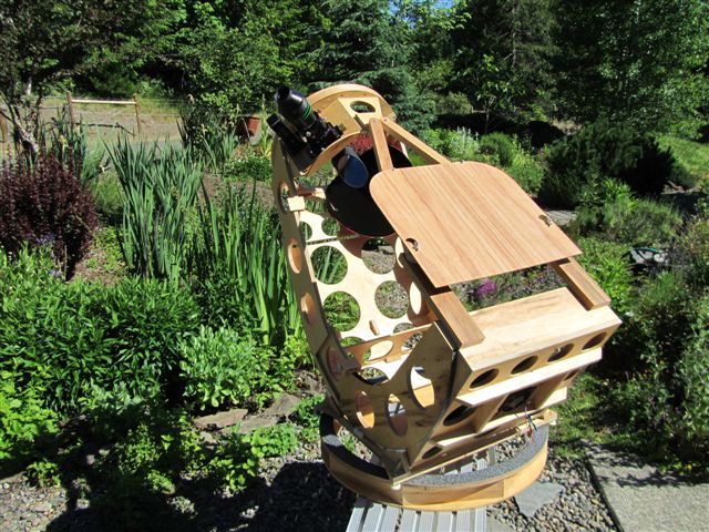
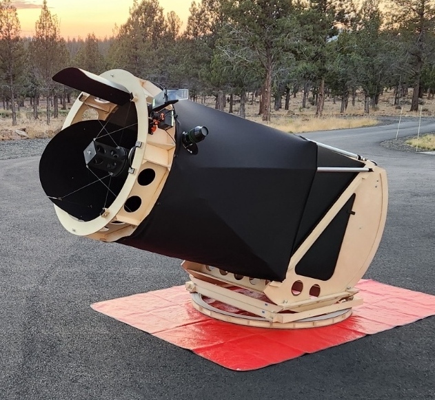
Code available on github at https://github.com/MelBartels/AstronomyCalculatorsJavaScript
end